US10666936B2 - Video decoding method and video decoding apparatus using merge candidate list - Google Patents
Video decoding method and video decoding apparatus using merge candidate list Download PDFInfo
- Publication number
- US10666936B2 US10666936B2 US15/780,047 US201615780047A US10666936B2 US 10666936 B2 US10666936 B2 US 10666936B2 US 201615780047 A US201615780047 A US 201615780047A US 10666936 B2 US10666936 B2 US 10666936B2
- Authority
- US
- United States
- Prior art keywords
- merge candidate
- inter
- intra
- prediction
- coding unit
- Prior art date
- Legal status (The legal status is an assumption and is not a legal conclusion. Google has not performed a legal analysis and makes no representation as to the accuracy of the status listed.)
- Expired - Fee Related, expires
Links
Images


Classifications
-
- H—ELECTRICITY
- H04—ELECTRIC COMMUNICATION TECHNIQUE
- H04N—PICTORIAL COMMUNICATION, e.g. TELEVISION
- H04N19/00—Methods or arrangements for coding, decoding, compressing or decompressing digital video signals
- H04N19/10—Methods or arrangements for coding, decoding, compressing or decompressing digital video signals using adaptive coding
- H04N19/102—Methods or arrangements for coding, decoding, compressing or decompressing digital video signals using adaptive coding characterised by the element, parameter or selection affected or controlled by the adaptive coding
- H04N19/103—Selection of coding mode or of prediction mode
- H04N19/11—Selection of coding mode or of prediction mode among a plurality of spatial predictive coding modes
-
- H—ELECTRICITY
- H04—ELECTRIC COMMUNICATION TECHNIQUE
- H04N—PICTORIAL COMMUNICATION, e.g. TELEVISION
- H04N19/00—Methods or arrangements for coding, decoding, compressing or decompressing digital video signals
- H04N19/10—Methods or arrangements for coding, decoding, compressing or decompressing digital video signals using adaptive coding
- H04N19/102—Methods or arrangements for coding, decoding, compressing or decompressing digital video signals using adaptive coding characterised by the element, parameter or selection affected or controlled by the adaptive coding
- H04N19/103—Selection of coding mode or of prediction mode
- H04N19/105—Selection of the reference unit for prediction within a chosen coding or prediction mode, e.g. adaptive choice of position and number of pixels used for prediction
-
- H—ELECTRICITY
- H04—ELECTRIC COMMUNICATION TECHNIQUE
- H04N—PICTORIAL COMMUNICATION, e.g. TELEVISION
- H04N19/00—Methods or arrangements for coding, decoding, compressing or decompressing digital video signals
- H04N19/10—Methods or arrangements for coding, decoding, compressing or decompressing digital video signals using adaptive coding
- H04N19/102—Methods or arrangements for coding, decoding, compressing or decompressing digital video signals using adaptive coding characterised by the element, parameter or selection affected or controlled by the adaptive coding
- H04N19/103—Selection of coding mode or of prediction mode
- H04N19/109—Selection of coding mode or of prediction mode among a plurality of temporal predictive coding modes
-
- H—ELECTRICITY
- H04—ELECTRIC COMMUNICATION TECHNIQUE
- H04N—PICTORIAL COMMUNICATION, e.g. TELEVISION
- H04N19/00—Methods or arrangements for coding, decoding, compressing or decompressing digital video signals
- H04N19/10—Methods or arrangements for coding, decoding, compressing or decompressing digital video signals using adaptive coding
- H04N19/134—Methods or arrangements for coding, decoding, compressing or decompressing digital video signals using adaptive coding characterised by the element, parameter or criterion affecting or controlling the adaptive coding
- H04N19/136—Incoming video signal characteristics or properties
- H04N19/137—Motion inside a coding unit, e.g. average field, frame or block difference
- H04N19/139—Analysis of motion vectors, e.g. their magnitude, direction, variance or reliability
-
- H—ELECTRICITY
- H04—ELECTRIC COMMUNICATION TECHNIQUE
- H04N—PICTORIAL COMMUNICATION, e.g. TELEVISION
- H04N19/00—Methods or arrangements for coding, decoding, compressing or decompressing digital video signals
- H04N19/10—Methods or arrangements for coding, decoding, compressing or decompressing digital video signals using adaptive coding
- H04N19/134—Methods or arrangements for coding, decoding, compressing or decompressing digital video signals using adaptive coding characterised by the element, parameter or criterion affecting or controlling the adaptive coding
- H04N19/157—Assigned coding mode, i.e. the coding mode being predefined or preselected to be further used for selection of another element or parameter
- H04N19/159—Prediction type, e.g. intra-frame, inter-frame or bidirectional frame prediction
-
- H—ELECTRICITY
- H04—ELECTRIC COMMUNICATION TECHNIQUE
- H04N—PICTORIAL COMMUNICATION, e.g. TELEVISION
- H04N19/00—Methods or arrangements for coding, decoding, compressing or decompressing digital video signals
- H04N19/10—Methods or arrangements for coding, decoding, compressing or decompressing digital video signals using adaptive coding
- H04N19/169—Methods or arrangements for coding, decoding, compressing or decompressing digital video signals using adaptive coding characterised by the coding unit, i.e. the structural portion or semantic portion of the video signal being the object or the subject of the adaptive coding
- H04N19/17—Methods or arrangements for coding, decoding, compressing or decompressing digital video signals using adaptive coding characterised by the coding unit, i.e. the structural portion or semantic portion of the video signal being the object or the subject of the adaptive coding the unit being an image region, e.g. an object
- H04N19/176—Methods or arrangements for coding, decoding, compressing or decompressing digital video signals using adaptive coding characterised by the coding unit, i.e. the structural portion or semantic portion of the video signal being the object or the subject of the adaptive coding the unit being an image region, e.g. an object the region being a block, e.g. a macroblock
-
- H—ELECTRICITY
- H04—ELECTRIC COMMUNICATION TECHNIQUE
- H04N—PICTORIAL COMMUNICATION, e.g. TELEVISION
- H04N19/00—Methods or arrangements for coding, decoding, compressing or decompressing digital video signals
- H04N19/10—Methods or arrangements for coding, decoding, compressing or decompressing digital video signals using adaptive coding
- H04N19/189—Methods or arrangements for coding, decoding, compressing or decompressing digital video signals using adaptive coding characterised by the adaptation method, adaptation tool or adaptation type used for the adaptive coding
- H04N19/196—Methods or arrangements for coding, decoding, compressing or decompressing digital video signals using adaptive coding characterised by the adaptation method, adaptation tool or adaptation type used for the adaptive coding being specially adapted for the computation of encoding parameters, e.g. by averaging previously computed encoding parameters
- H04N19/198—Methods or arrangements for coding, decoding, compressing or decompressing digital video signals using adaptive coding characterised by the adaptation method, adaptation tool or adaptation type used for the adaptive coding being specially adapted for the computation of encoding parameters, e.g. by averaging previously computed encoding parameters including smoothing of a sequence of encoding parameters, e.g. by averaging, by choice of the maximum, minimum or median value
-
- H—ELECTRICITY
- H04—ELECTRIC COMMUNICATION TECHNIQUE
- H04N—PICTORIAL COMMUNICATION, e.g. TELEVISION
- H04N19/00—Methods or arrangements for coding, decoding, compressing or decompressing digital video signals
- H04N19/44—Decoders specially adapted therefor, e.g. video decoders which are asymmetric with respect to the encoder
-
- H—ELECTRICITY
- H04—ELECTRIC COMMUNICATION TECHNIQUE
- H04N—PICTORIAL COMMUNICATION, e.g. TELEVISION
- H04N19/00—Methods or arrangements for coding, decoding, compressing or decompressing digital video signals
- H04N19/50—Methods or arrangements for coding, decoding, compressing or decompressing digital video signals using predictive coding
- H04N19/503—Methods or arrangements for coding, decoding, compressing or decompressing digital video signals using predictive coding involving temporal prediction
- H04N19/51—Motion estimation or motion compensation
- H04N19/513—Processing of motion vectors
-
- H—ELECTRICITY
- H04—ELECTRIC COMMUNICATION TECHNIQUE
- H04N—PICTORIAL COMMUNICATION, e.g. TELEVISION
- H04N19/00—Methods or arrangements for coding, decoding, compressing or decompressing digital video signals
- H04N19/50—Methods or arrangements for coding, decoding, compressing or decompressing digital video signals using predictive coding
- H04N19/503—Methods or arrangements for coding, decoding, compressing or decompressing digital video signals using predictive coding involving temporal prediction
- H04N19/51—Motion estimation or motion compensation
- H04N19/56—Motion estimation with initialisation of the vector search, e.g. estimating a good candidate to initiate a search
Definitions
- the present disclosure relates to a video decoding method and a video decoding apparatus, and more particularly, to a method and apparatus for performing inter prediction by using a merge candidate list including a temporal neighboring block and a spatial neighboring block.
- Image data is encoded by a codec in accordance with a predetermined data compression standard, for example, the Moving Picture Expert Group (MPEG) standard, and is then stored in a recording medium in the form of a bitstream or transmitted through a communication channel.
- MPEG Moving Picture Expert Group
- an image compression technique may be effectively implemented through a process of dividing an image to be encoded by an arbitrary method or manipulating data.
- a prediction technique is the most widely used technique for encoding a video including temporally consecutive images.
- the prediction technique is a technique for encoding data of a current block by using a block having information with similar tendency to the current block in the image. If the data of the current block is directly encoded, the amount of data generated by the encoding is relatively large. Therefore, only the difference information between the data of another block that has already been encoded and the data of the current block is encoded and the data generated by the encoding is transmitted or stored.
- the information generated by encoding the data of the current block through the prediction technique may be defined as prediction information.
- information indicating another block used to encode the current block is also encoded as prediction information and then transmitted or stored.
- the prediction technique a process of determining another block used to encode the current block is preceded.
- the prediction technique since the current block is predicted by using information having similar tendency to the current block, neighboring samples spatially adjacent to the current block in the current image are used, or collocated blocks in spatially adjacent neighboring blocks and temporally different images are used.
- the sample value of the current block may be determined using neighboring sample values spatially adjacent to the current block.
- motion information of the current block is determined using prediction information of the adjacent block or the neighboring block such as the collocated block.
- the sample value of the current block may be determined using the sample value of the reference block indicated by the motion information of the current block.
- the range of the information to be referred to as the prediction information of the current block in the prediction information of the adjacent block or the collocated block may be changed according to whether a mode is a skip mode, a merge mode, or an advanced motion vector prediction (AMVP) mode among the inter prediction techniques.
- a mode is a skip mode, a merge mode, or an advanced motion vector prediction (AMVP) mode among the inter prediction techniques.
- AMVP advanced motion vector prediction
- a merge candidate list is used to determine a neighboring block to be used for inter prediction.
- the motion information of the current block may be determined using one piece of motion information among at least one candidate block included in the merge candidate list.
- a video encoding apparatus or a decoding apparatus Provided are a video encoding apparatus or a decoding apparatus, and a method of effectively determining a merge candidate list to be used for inter prediction.
- a video encoding method includes: determining whether it is possible to include an intra merge candidate in a merge candidate list; when it is possible to include the intra merge candidate in the merge candidate list, determining a merge candidate list including at least one of the intra merge candidate and an inter merge candidate of a current block; generating prediction samples of the current block by using a prediction candidate selected from the determined merge candidate list; and reconstructing the current block by using residual samples between the current block and the prediction samples of the current block.
- the inter merge candidate is a prediction block determined by motion information of at least one block selected from among a neighboring block spatially adjacent to the current block and a collocated block located corresponding to a position of the current block in a picture temporally adjacent to the current block, and the intra merge candidate is a prediction block determined using neighboring samples spatially adjacent to the current block.
- a video decoding apparatus includes: a merge candidate list determiner configured to determine whether it is possible to include an intra merge candidate in a merge candidate list, and when it is possible to include the intra merge candidate in the merge candidate list, determine a merge candidate list including at least one of the intra merge candidate and an intra merge candidate of a current block; and a decoder configured to generate prediction samples of the current block by using a prediction candidate selected from the determined merge candidate list, and reconstruct the current block by using the prediction samples of the current block and residual samples of the current block.
- a video encoding method includes: when an intra merge candidate is included in a merge candidate list, determining a merge candidate list including at least one of an intra merge candidate and an inter merge candidate of a current block; generating a merge candidate index indicating a prediction candidate selected for generating prediction samples of the current block in the determined merge candidate list; and encoding residual samples between the current block and the prediction samples of the current block and the merge candidate index, and generating a bitstream including the encoded residual samples and merge candidate index.
- a non-transitory computer-readable recording medium having stored thereon a computer program for performing a video decoding method including: determining whether it is possible to include an intra merge candidate in a merge candidate list; when it is possible to include the intra merge candidate in the merge candidate list, determining a merge candidate list including at least one of the intra merge candidate and an inter merge candidate of a current block; generating prediction samples of the current block by using a prediction candidate selected from the determined merge candidate list; and reconstructing the current block by using the prediction samples of the current block and residual samples of the current block.
- a non-transitory computer-readable recording medium having stored thereon a computer program for performing a video encoding method including: when an intra merge candidate is included in a merge candidate list, determining a merge candidate list including at least one of an intra merge candidate and an inter merge candidate of a current block; generating a merge candidate index indicating a prediction candidate selected for generating prediction samples of the current block in the determined merge candidate list; and encoding residual samples between the current block and the prediction samples of the current block and the merge candidate index, and generating a bitstream including the encoded residual samples and merge candidate index.
- FIG. 1A is a block diagram of a video decoding apparatus according to an embodiment.
- FIG. 1B is a flowchart of a video decoding method according to an embodiment.
- FIG. 2A is a block diagram of a video encoding apparatus according to an embodiment.
- FIG. 2B is a flowchart of a video encoding method according to an embodiment.
- FIG. 3A illustrates inter merge candidates that can be included in a merge candidate list.
- FIGS. 3B and 3C illustrate intra merge candidates that can be included in a merge candidate list, according to an embodiment.
- FIG. 4 illustrates a merge candidate list in which an inter merge candidate and an intra merge candidate are included at the same time, according to an embodiment.
- FIG. 5 illustrates an inter merge candidate list including an inter merge candidate and an intra merge candidate list including an intra merge candidate, according to an embodiment.
- FIGS. 6A, 6B, and 6C illustrate an intra merge candidate list in which a weighted average prediction sample value of an inter merge candidate and an intra merge candidate is included as an inter-intra merge candidate, according to an embodiment.
- FIG. 7 illustrates a merge candidate list including an inter merge candidate and an inter-intra merge candidate, according to an embodiment.
- FIG. 8 illustrates an intra merge candidate list including an inter merge candidate, an intra merge candidate, and an inter-intra merge candidate, according to an embodiment.
- FIG. 9 illustrates a syntax for signalling intra merge information, according to an embodiment.
- FIG. 10 illustrates processes of determining at least one coding unit as a current coding unit is split, according to an embodiment.
- FIG. 11 illustrates processes of determining at least one coding unit when a coding unit having a non-square shape is split, according to an embodiment.
- FIG. 12 illustrates processes of splitting a coding unit, based on at least one of a block shape information and split shape information, according to an embodiment.
- FIG. 13 illustrates a method of determining a certain coding unit from among an odd number of coding units, according to an embodiment.
- FIG. 14 illustrates an order of processing a plurality of coding units when the plurality of coding units are determined when a current coding unit is split, according to an embodiment.
- FIG. 15 illustrates processes of determining that a current coding unit is split into an odd number of coding units when a coding unit is not processable in a certain order, according to an embodiment.
- FIG. 16 illustrates processes of determining at least one coding unit when a first coding unit is split, according to an embodiment.
- FIG. 17 illustrates that a shape into which a second coding unit is splittable is restricted when the second coding unit having a non-square shape determined when a first coding unit is split satisfies a certain condition, according to an embodiment.
- FIG. 18 illustrates processes of splitting a coding unit having a square shape when split shape information is unable to indicate that a coding unit is split into four square shapes, according to an embodiment.
- FIG. 19 illustrates that an order of processing a plurality of coding units may be changed according to processes of splitting a coding unit, according to an embodiment.
- FIG. 20 illustrates processes of determining a depth of a coding unit as a shape and size of the coding unit are changed, when a plurality of coding units are determined when the coding unit is recursively split, according to an embodiment.
- FIG. 21 illustrates a part index (PID) for distinguishing depths and coding units, which may be determined according to shapes and sizes of coding units, according to an embodiment.
- PID part index
- FIG. 22 illustrates that a plurality of coding units are determined according to a plurality of certain data units included in a picture, according to an embodiment.
- FIG. 23 illustrates a processing block serving as a criterion of determining a determination order of reference coding unit included in a picture, according to an embodiment.
- a video encoding method includes: determining whether it is possible to include an intra merge candidate in a merge candidate list; when it is possible to include the intra merge candidate in the merge candidate list, determining a merge candidate list including at least one of the intra merge candidate and an inter merge candidate of a current block; generating prediction samples of the current block by using a prediction candidate selected from the determined merge candidate list; and reconstructing the current block by using residual samples between the current block and the prediction samples of the current block.
- the inter merge candidate is a prediction block determined by motion information of at least one block selected from among a neighboring block spatially adjacent to the current block and a collocated block located corresponding to a position of the current block in a picture temporally adjacent to the current block, and the intra merge candidate is a prediction block determined using neighboring samples spatially adjacent to the current block.
- a video decoding apparatus includes: a merge candidate list determiner configured to determine whether it is possible to include an intra merge candidate in a merge candidate list, and when it is possible to include the intra merge candidate in the merge candidate list, determine a merge candidate list including at least one of the intra merge candidate and an intra merge candidate of a current block; and a decoder configured to generate prediction samples of the current block by using a prediction candidate selected from the determined merge candidate list, and reconstruct the current block by using the prediction samples of the current block and residual samples of the current block.
- a video encoding method includes: when an intra merge candidate is included in a merge candidate list, determining a merge candidate list including at least one of an intra merge candidate and an inter merge candidate of a current block; generating a merge candidate index indicating a prediction candidate selected for generating prediction samples of the current block in the determined merge candidate list; and encoding residual samples between the current block and the prediction samples of the current block and the merge candidate index, and generating a bitstream including the encoded residual samples and merge candidate index.
- unit refers to a hardware component such as software or hardware component such as FPGA or ASIC, and “unit” performs certain functions. However, “unit” is not limited to software or hardware. A “unit” may be configured in an addressable storage medium or to reproduce one or more processors.
- a “unit” includes components, such as software components, object-oriented software components, class components, and task components, processes, functions, attributes, procedures, subroutines, segments of programs codes, drivers, firmware, microcodes, circuits, data, databases, data structures, tables, arrays, and variables. Functions provided in the components and the “units” may be combined with a smaller number of components and “units” or may be separated from additional components and “units”.
- an “image” may indicate a still image, such as a still picture of a video, or a moving picture, that is, the video itself.
- sample indicates data allocated to a sampling position of an image and data to be processed.
- pixel values in an image of a spatial domain or transformation coefficients on a transformation domain may be samples.
- the unit including at least one sample may be defined as a block.
- a video encoding apparatus, a video decoding apparatus, a video encoding method, and a video decoding method, according to embodiments, will be described below with reference to FIGS. 1 through 23 .
- a method and apparatus for performing inter prediction by using a merge candidate list determined according to embodiments, will be described with reference to FIGS. 1 through 9
- a method of determining a data unit of an image, according to embodiments, will be described with reference to FIGS. 10 through 23 .
- FIGS. 1A through 9 a method and apparatus for performing inter prediction so as to encode or decode a block of an image, according to embodiment of the present disclosure, will be described with reference to FIGS. 1A through 9 .
- FIG. 1A is a block diagram of a video decoding apparatus 100 according to an embodiment.
- the video decoding apparatus 100 may include a merge candidate list determiner 110 and a decoder 120 .
- the merge candidate list determiner 110 and the decoder 120 may operate as individual processors, or may operate under the control of a central processor.
- the video decoding apparatus 100 may further include a memory or a storage for storing data received from the outside and data generated by the merge candidate list determiner 110 and the decoder 120 .
- the video decoding apparatus 100 may perform inter prediction according to a skip mode or a merge mode.
- the merge candidate list determiner 110 may determine a merge candidate list including at least one merge candidate so as to perform the inter prediction according to the skip mode or the merge mode.
- the merge candidate included in the merge candidate list may be a prediction block determined based on motion information of at least one block selected from among a neighboring block spatially adjacent to a current block and a collocated block located corresponding to a position of the current block in a picture temporally adjacent to the current block.
- the prediction block determined based on the motion information of at least one block selected from among the neighboring block and the collocated block is referred to as an “inter merge candidate”.
- an “intra merge candidate” is proposed as a concept in contrast to the “inter merge candidate”.
- the prediction block determined using the neighboring samples spatially adjacent to the current block may be used as the merge candidate.
- the merge candidate is referred to as an “intra merge candidate” in the present disclosure.
- the inter merge candidate will be described with reference to FIG. 3A
- the intra merge candidate will be described with reference to FIGS. 3B and 3C .
- the merge candidate list determiner 110 may determine whether it is possible to include the intra merge candidate in the merge candidate list.
- the merge candidate list determiner 110 may include at least one of an inter merge candidate and an intra merge candidate of the current block.
- the decoder 12 may generate prediction samples of the current block by using the prediction candidate selected from the merge candidate list generated by the merge candidate list determiner 110 .
- the decoder 12 may reconstruct the current block by using residual samples between the current block and the prediction samples of the current block.
- FIG. 1B is a flowchart of a video decoding method according to an embodiment.
- the video decoding apparatus 100 may determine whether it is possible to include an intra merge candidate in a merge candidate list.
- the video decoding apparatus 100 may acquire, from a bitstream, intra merge information indicating whether it is possible to include the intra merge candidate in the merge candidate list.
- the video decoding apparatus 100 may perform entropy decoding on the bitstream to acquire a prediction mode flag for a current block.
- the prediction mode flag indicates a prediction mode other than the intra prediction
- the video decoding apparatus 100 may parse a skip flag for the current block from the bitstream.
- the video decoding apparatus 100 when the skip flag indicates the inter prediction according to the skip mode, the video decoding apparatus 100 does not parse the merge flag from the bitstream. However, when the skip flag does not indicate the inter prediction according to the skip mode, the video decoding apparatus 100 may further parse the merge flag from the bitstream. When the merge flag indicates the inter prediction according to the merge mode, the video decoding apparatus 100 may further parse intra merge information from the bitstream.
- the video decoding apparatus 100 may further parse intra merge information from the bitstream.
- the video decoding apparatus 100 may determine the merge candidate list including at least one of the inter merge candidate and the intra merge candidate of the current block.
- the video decoding apparatus 100 may determine the merge candidate list not including the intra merge candidate of the current block. That is, the merge candidate list including only the inter merge candidate may be determined.
- the video decoding apparatus 100 may determine the merge candidate list including at least one of the inter merge candidate and the intra merge candidate of the current block in operation S 140 .
- the video decoding apparatus 100 may generate prediction samples of the current block by using the prediction candidate selected from the merge candidate list generated in operation S 140 .
- the inter merge candidate according to the embodiment may be a prediction block determined by motion information of at least one block selected from among the neighboring block spatially adjacent to the current block and the collocated block.
- the collocated block may be a block located within a picture temporally adjacent to the current block while corresponding to the position of the current block in the current image. Therefore, the motion information of the current block may be predicted by using the motion information of at least one selected from the neighboring block of the current block and the collocated block, and the prediction samples of the current block may be determined using sample values of the reference block indicated by the predicted motion information. Therefore, the prediction block according to the inter merge candidate may be a block including the prediction sample values determined using the sample value of the reference block.
- the intra merge candidate according to the embodiment may be a prediction block determined using the neighboring samples spatially adjacent to the current block.
- the block including the sample values determined using the sample values of the samples adjacent to the outermost samples in the current block while located outside the current block may be determined as the prediction block, and such a prediction block may be included in the merge candidate list as the intra merge candidate.
- the intra merge candidate may be determined using a predetermined number of neighboring samples spatially adjacent to the current block in a predetermined direction.
- the intra merge candidate may be determined using a predetermined number of neighboring samples adjacent in a predetermined direction and determined from a direction indicated by a most probable mode (MPM) index acquired from the bitstream.
- the MPM index may indicate one of a predetermined number of intra prediction modes that usable for the intra prediction of the current block.
- the predetermined number of intra prediction modes may include an intra prediction mode of a neighboring block and a specific intra prediction mode.
- the sample value according to the intra merge candidate determined using the neighboring samples spatially adjacent to the current block, and the samples determined by the weighted average of the prediction sample values according to at least one inter merge candidate may be determined as the inter-intra merge candidate, and the inter-intra merge candidate may be included in the merge candidate list.
- the video decoding apparatus 100 may acquire, from the bitstream, the merge candidate index indicating one candidate in the merge candidate list.
- the video decoding apparatus 100 may generate the prediction samples of the current block by using the prediction candidate indicated by the merge candidate index in the merge candidate list.
- the video decoding apparatus 100 may determine the inter merge candidate list including at least one inter merge candidate, and may determine the intra merge candidate list including at least one intra merge candidate.
- the intra merge candidate list may further include the inter-intra merge candidate. Therefore, the video decoding apparatus 100 according to the embodiment may generate prediction samples of the current block by using the prediction candidate selected from among the inter merge candidate list and the intra merge candidate list. In this case, the prediction samples may be determined using the merge candidate index indicating one of the candidates of the inter merge candidate list and the candidates of the intra merge candidate list.
- the video decoding apparatus 100 may determine one merge candidate list including at least one of the inter merge candidate, the intra merge candidate, and the inter-intra merge candidate.
- One merge candidate list may further include the inter-intra merge candidate. Therefore, the video decoding apparatus 100 may generate prediction samples of the current block by using the prediction candidate selected from one merge candidate list. In this case, the prediction samples may be determined using the merge candidate index indicating one of the merge candidates included in one merge candidate list.
- the merge candidate list including at least one of the inter merge candidate, the intra merge candidate, and the inter-intra merge candidate will be described with reference to FIGS. 4, 5, 6A, 6B, 6C, 7, and 8 .
- the video decoding apparatus 100 may generate the prediction samples of the current block by using the prediction candidate indicated by the merge candidate index in the merge candidate list.
- the video decoding apparatus 100 may acquire motion vector differential (mvd) information from the bitstream.
- the video decoding apparatus 100 may determine one candidate in the merge candidate list, based on the acquired merge candidate index.
- a prediction direction L 0 or L 1 , a reference index, and a motion vector predictor (mvp) of the current block may be determined using a prediction direction L 0 or L 1 , a reference index, and a motion vector of the candidate block.
- a motion vector of the current block may be determined by adding the motion vector predictor (mvp) and the motion vector differential (mvd) value.
- the sample values of the reference block indicated by the motion vector of the current block may be determined as the prediction sample values according to the inter merge candidate of the current block.
- the video decoding apparatus 100 may acquire the intra prediction mode information indicating the intra prediction direction from the bitstream.
- the video decoding apparatus 100 may determine the prediction sample values according to the intra merge candidate of the current block by using the neighboring sample values indicated by the intra prediction mode.
- the neighboring samples according to the intra merge candidate will be described with reference to FIG. 3B
- the intra prediction direction and the intra prediction mode will be described with reference to FIG. 3C .
- the video decoding apparatus 100 may reconstruct the current block by using the residual samples between the current block and the prediction samples of the current block.
- the video decoding apparatus 100 may perform entropy decoding on the bitstream, parse the residual signals of the blocks according to the block scan order and the scan order of the samples within the block, and acquire the residual signal of the current block.
- the video decoding apparatus 100 may perform inverse-quantization and inverse-transformation on the residual signals of the current block so as to reconstruct the residual samples of the spatial domain of the current block.
- the video decoding apparatus 100 may reconstruct the samples of the current block by adding the reconstructed residual samples of the current block to the prediction samples of the current block determined by performing the inter prediction.
- the video decoding apparatus 100 may reconstruct the current image by reconstructing the samples for each block.
- FIG. 2A is a block diagram of a video encoding apparatus 200 according to an embodiment.
- the video encoding apparatus 200 includes an inter predictor 210 and an encoder 220 .
- the inter predictor 210 and the encoder 220 may operate as individual processors, or may operate under the control of a central processor.
- the video encoding apparatus 200 may further include a memory or a storage for storing data generated during an encoding process and data generated by the inter predictor 210 and the encoder 220 .
- the video encoding apparatus 200 may perform inter prediction according to a skip mode or a merge mode.
- the inter predictor according to the embodiment may determine a merge candidate list including at least one merge candidate so as to perform the inter prediction according to the skip mode or the merge mode.
- the inter predictor 210 may determine the merge candidate list including at least one of an inter merge candidate and an intra merge candidate of the current block.
- the merge candidate list used for performing the inter prediction in the skip mode or the merge mode may include at least one of the inter merge candidate, the intra merge candidate, and the inter-intra merge candidate as the merge candidate.
- the inter merge candidate according to the embodiment may include a prediction block determined by motion information of at least one block selected from among the neighboring block of the current block and the collocated block.
- the intra merge candidate according to the embodiment may include a prediction block determined using the neighboring samples spatially adjacent to the current block.
- the inter-intra merge candidate according to the embodiment may include a prediction block having a weighted average of the prediction sample value according to the inter merge candidate and the prediction sample value according to the intra merge candidate as the prediction sample value.
- the inter predictor 210 may generate the merge candidate index indicating the prediction candidate selected for generating the prediction samples of the current block in the merge candidate list.
- the encoder 220 may encode the residual samples between the current block and the prediction samples of the current block and the merge candidate index, and generate a bitstream including the encoded information.
- FIG. 2B is a flowchart of a video encoding method according to an embodiment.
- the video encoding apparatus 200 may determine the merge candidate list including at least one of the inter merge candidate and the intra merge candidate of the current block.
- the video encoding apparatus 200 may determine the merge candidate index indicating the prediction candidate selected for generating the prediction samples of the current block in the merge candidate list generated in operation S 230 , and encode a value indicating the merge candidate index.
- the inter merge candidate, the intra merge candidate, and the inter-intra merge candidate used in the video encoding apparatus 200 according to the embodiment correspond to the inter merge candidate, the intra merge candidate, and the inter-intra merge candidate described above in the video decoding apparatus 100 according to various embodiments, respectively, a redundant description thereof is omitted.
- the video encoding apparatus 200 may determine the inter merge candidate list including at least one inter merge candidate, and may determine the intra merge candidate list including at least one intra merge candidate.
- the intra merge candidate list may further include the inter-intra merge candidate. Therefore, the video encoding apparatus 200 according to the embodiment may generate prediction samples of the current block by using the prediction candidate selected from among the inter merge candidate list and the intra merge candidate list. In this case, the video encoding apparatus 200 may encode the merge candidate index indicating one of the candidates of the inter merge candidate list and the candidates of the intra merge candidate list.
- the video encoding apparatus 200 may determine one merge candidate list including at least one inter merge candidate and at least one intra merge candidate.
- One merge candidate list may further include the inter-intra merge candidate. Therefore, the video encoding apparatus 200 may generate prediction samples of the current block by using the prediction candidate selected from one merge candidate list. In this case, the video encoding apparatus 200 may encode the merge candidate index indicating one of the merge candidates included in one merge candidate list.
- the video encoding apparatus 200 may perform the inter prediction based on the candidate included in the merge candidate list, and compare rate-distortion (RD) costs generated by the inter prediction for each candidate.
- the video encoding apparatus 200 according to the embodiment may select the merge candidate generating the minimum RD cost among the candidates, and determine the merge candidate index indicating the selected merge candidate among the merge candidates included in the merge candidate list.
- the video encoding apparatus 200 may encode the residual samples between the current block and the prediction samples of the current block and the merge candidate index. For example, the video encoding apparatus 200 may perform entropy encoding on the residual samples of the current block and the merge candidate index, and generate the bitstream including the generated bits. In addition, the video encoding apparatus 200 may perform transformation and quantization on the samples of the current block so as to generate quantized transformation coefficients of the samples, and perform inverse-quantization and inverse-transformation on the quantized transformation coefficients so as to reconstruct the samples of the spatial domain. The video encoding apparatus 200 may determine residual samples that are the difference values between the prediction samples of the current block determined according to the prediction mode and the reconstructed samples of the current block.
- the video encoding apparatus 200 may optionally determine whether the intra merge candidate is included in the merge candidate list. Therefore, the video encoding apparatus 200 may generate intra merge information indicating whether the intra merge candidate is included in the merge candidate list. The video encoding apparatus 200 may encode the intra merge information, and encode the merge candidate index when the intra merge candidate is included in the merge candidate list.
- the video encoding apparatus 200 may further encode a prediction mode flag for the current block.
- the video encoding apparatus 200 may further encode the prediction mode flag indicating whether the prediction mode is the intra prediction mode.
- the video encoding apparatus 200 may further encode a skip flag indicating whether the current block is predicted in the skip mode or a merge flag indicating whether the current block is predicted in a merge mode.
- the video encoding apparatus 200 may encode a skip mode flag indicating that the current block is predicted in the skip mode, and encode only the index indicating the neighboring block that is to refer to the motion information, but may no longer encode the information about the merge mode.
- the video encoding apparatus 200 may encode the skip mode flag indicating that the current block is not the skip mode, and further encode the merge flag indicating whether the current block is predicted in the merge mode.
- the video encoding apparatus 200 may further encode the merge mode flag indicating that the current block is predicted in the merge mode, the intra merge information, and the merge candidate index information.
- the video encoding apparatus 200 may further encode motion vector differential (mvd) information.
- the video encoding apparatus 200 may determine the motion vector predictor of the current block by using the motion vector of the candidate block. Therefore, motion vector difference information that is a difference value between the motion vector and the motion vector predictor of the current block may be determined.
- the sample values of the reference block indicated by the motion vector of the current block may be determined as the prediction sample values according to the inter merge candidate of the current block, and the difference values between the prediction samples and the reconstructed samples of the current block may be encoded as residual information.
- the video encoding apparatus 200 may further encode the intra prediction mode information indicating the intra prediction direction.
- the video encoding apparatus 200 may determine the prediction sample values according to the intra merge candidate of the current block by using the neighboring sample values indicated by the intra prediction mode.
- the neighboring samples according to the intra merge candidate will be described with reference to FIG. 3B , and the intra prediction direction and the intra prediction mode will be described with reference to FIG. 3C .
- the neighboring sample values spatially adjacent to the current block, as well as the motion information of the neighboring block of the current block or the collocated block, are included in the merge candidate list as the merge candidate that is to be referred to in the inter prediction of the current block, so as to predict the current block accurately and effectively.
- FIG. 3A illustrates inter merge candidates that can be included in the merge candidate list.
- the video decoding apparatus 100 may determine a merge mode list so as to perform inter prediction on a current block 300 according to a skip mode or a merge mode.
- sample values of a reference block indicated by a prediction direction L 0 or L 1 , a reference index, and a motion vector of the current block which are determined using a prediction direction L 0 or L 1 , a reference index, and a motion vector of a candidate block determined in the merge mode list, may be determined as samples values of the current block 300 .
- a prediction direction L 0 or L 1 , a reference index, and a motion vector predictor of the current block may be determined using a prediction direction L 0 or L 1 , a reference index, and a motion vector of a candidate block determined in the merge mode list, and a motion vector of the current block 300 may be determined by adding the motion vector predictor and the motion vector difference information. Therefore, sample values of the reference block indicated by the prediction direction L 0 or L 1 , the reference index, and the motion vector of the current block may be determined as prediction sample values of the current block, and sample values of the current block 300 may be determined by adding the prediction sample values and the residual sample values.
- a process of determining another block used to encode the current block is preceded. Since the block having similar tendency to the current block is generally used, neighboring blocks spatially adjacent to the current block in the current image or blocks in a temporally different image located at a position similar to a position at which the current block is located in the current image may be used.
- the merge candidate list according to the embodiment may include at least one inter merge candidate.
- the inter merge candidate may include at least one block selected from among neighboring blocks A 0 310 , A 1 312 , B 0 314 , B 1 316 , and B 2 318 spatially adjacent to the current block, and a collocated block Col 320 located corresponding to the position of the current block in a picture temporally adjacent to the current block.
- the neighboring block A 0 310 may be a block including a sample adjacent to the outside in a left lower diagonal direction of a sample located at a left lower corner in samples of the current block 300 among blocks adjacent to the outside of the current block 300 .
- the neighboring block A 1 312 may be a block including a sample adjacent to the left outside of a sample located at a left lower corner in the samples of the current block 300 among the blocks adjacent to the outside of the current block 300 .
- the neighboring block B 0 314 may be a block including a sample adjacent to the outside in a right upper diagonal direction of a sample located at a right upper corner in the samples of the current block 300 among the blocks adjacent to the outside of the current block 300 .
- the neighboring block B 1 316 may be a block including a sample adjacent to the upper outside of a sample located at a right upper corner in the samples of the current block 300 among the blocks adjacent to the outside of the current block 300 .
- the neighboring block B 2 318 may be a block including a sample adjacent to the outside in a left upper diagonal direction of a sample located at a left upper corner in the samples of the current block 300 among the blocks adjacent to the outside of the current block 300 .
- the collocated block Col 320 may be a block existing at a position corresponding to the current block 300 in the current image among blocks within an image (collocated image) temporally different from the current image including the current block. For example, a same location block including the position corresponding to the coordinates of the current block 300 in the current image may be selected from among the blocks of the collocated image, and a block H adjacent to the outside in a diagonal direction at a right lower corner of the selected block may be determined as the collocated block 320 . However, when valid motion information about the block H is not defined, a block including the central position of the same location block may be determined as the collocated block 320 .
- the current block 300 may be a coding unit (CU), or may be a sub-block determined within the coding unit for the prediction of the coding unit.
- CU coding unit
- FIGS. 3B and 3C illustrate intra merge candidates that can be included in a merge candidate list, according to an embodiment.
- an intra merge candidate may include a prediction block determined using neighboring samples spatially adjacent to a current block 350 .
- the neighboring samples may be selected from among reconstructed samples adjacent to the outside of the current block 300 .
- neighboring samples may include P( ⁇ 1, ⁇ 1) and P(2N ⁇ 1, ⁇ 1) and may include samples horizontally located in a row between P( ⁇ 1, ⁇ 1) and P(2N ⁇ 1, ⁇ 1).
- the neighboring samples may include P( ⁇ 1, ⁇ 1) and P( ⁇ 1, 2N ⁇ 1) and may include samples vertically located in a row between P( ⁇ 1, ⁇ 1) and P( ⁇ 1, 2N ⁇ 1).
- the current block 350 may be a coding unit (CU), or may be a sub-block determined within the coding unit for the transformation of the coding unit.
- CU coding unit
- the neighboring samples that may be referred to for the intra prediction of the current block may be changed according to the prediction direction of the intra prediction. That is, the samples that are referred to among the neighboring samples horizontally arranged from P( ⁇ 1, ⁇ 1) to P(2N ⁇ 1, ⁇ 1) may be changed according to the prediction direction, and the samples that are referred to among the neighboring samples vertically arranged from P( ⁇ 1, ⁇ 1) to P( ⁇ 1, 2N ⁇ 1) may be changed according to the prediction direction.
- each arrow means the prediction direction indicating the neighboring sample for reference from the current block, and each number indicates an index corresponding to the intra prediction mode.
- the intra prediction mode in which a specific prediction direction is matched like the arrow is referred to as an angular mode, and the intra prediction mode in which the specific prediction direction is not matched is referred to as a non-angular mode.
- Examples of the non-angular mode include a planar mode and a DC mode.
- an intra prediction mode index 0 indicates a planar mode
- an intra prediction mode index 1 indicates a DC mode.
- the prediction value is determined so that the gradation according to the change in the neighboring sample values is reflected to the prediction sample. Therefore, similar to the gradation of the neighboring sample values, prediction sample values may gradually increase or decrease according to the increase in the coordinates of the prediction samples. According to the DC mode, the current prediction sample values may be uniformly determined by the average value of the neighboring samples surrounding the current block 350 .
- the angular mode is a prediction mode according to the prediction direction matching the intra prediction mode indices 2 to 34 illustrated in FIG. 3C . That is, the prediction sample values of the current block 350 may be determined according to the tendency of sample values located in a specific arrow direction among the neighboring samples of the current block 350 . To this end, the prediction sample values for the samples located in the corresponding direction within the current block 350 may be determined by taking sample values located in the prediction direction among the neighboring samples of the current block 350 . The prediction block including such prediction sample values may be determined.
- the video decoding apparatus 100 may use a predetermined number of intra prediction modes so as to determine the intra merge candidate.
- the prediction block according to one of four intra modes including a planar mode (intra prediction mode index 0 ), a DC mode (intra prediction mode index 1 ), a vertical mode (intra prediction mode index 26 ), and a horizontal mode (intra prediction mode index 10 ) among the intra prediction modes illustrated in FIG. 3C may be used as the intra merge candidate.
- the video decoding apparatus 100 may use, as the intra merge candidate, the prediction block according to the intra prediction mode determined based on the intra mode of the neighboring block or the previous picture.
- the prediction block according to an MPM index indicating one of the intra prediction modes of the neighboring blocks may be used as the intra merge candidate.
- the video decoding apparatus 100 may determine the merge candidate list including at least one intra merge candidate.
- the merge candidate list according to various embodiments will be described with reference to FIGS. 4, 5, 6A, 6B, 6C, 7, and 9 .
- “MVm” (m is an integer) indicates inter merge candidates
- “IPMn” (n is an integer) indicates intra merge candidates.
- “IPMn&&MVm” indicates an inter-intra merge candidate in which the intra merge candidate “IPMn” and the inter merge candidate “MVm” are combined.
- the inter-intra merge candidate “IPMn&MVm” may be determined by the weighted average of the prediction value according to the intra merge candidate “IPMn” and the prediction value according to the inter merge candidate “MVm”.
- FIG. 4 illustrates a merge candidate list in which an inter merge candidate and an intra merge candidate are included at the same time, according to an embodiment.
- the video decoding apparatus 100 may determine a merge candidate list 400 or 450 including at least one inter merge candidate and at least one intra merge candidate.
- the video decoding apparatus 100 may generate the merge candidate list 400 including inter merge candidates MV 1 , MV 2 , MV 3 , . . . , VMm, and add intra merge candidates IPM 1 , IPM 2 , . . . , IPMn to the merge candidate list 400 .
- the video decoding apparatus 100 may determine the merge candidate list 400 including the inter merge candidates MV 1 , MV 2 , MV 3 , . . . , VMm, and determine the merge candidate list 400 by adding the intra merge candidates IPM 1 , IPM 2 , . . . , IPMn between the inter merge candidates of the merge candidate list 400 one by one.
- the video decoding apparatus 100 may perform the inter prediction by using one candidate indicated by the merge candidate index among the inter merge candidates and the intra merge candidates included in the merge candidate list 400 or 450 .
- the video encoding apparatus 200 may also generate the merge candidate list 400 or 450 including the inter merge candidates MV 1 , MV 2 , MV 3 , . . . , VMm, and add the intra merge candidates IPM 1 , IPM 2 , . . . , IPMn to the merge candidate list 400 or 450 .
- the video encoding apparatus 200 may encode the merge candidate index indicating one candidate used for the inter prediction among the inter merge candidates and the intra merge candidates included in the merge candidate list 400 or 450 .
- FIG. 5 illustrates an inter merge candidate list including an inter merge candidate and an intra merge candidate list including an intra merge candidate, according to an embodiment.
- the video decoding apparatus 100 may determine an inter merge candidate list 500 including at least one inter merge candidate, and an intra merge candidate list 550 including at least one intra merge candidate.
- the video decoding apparatus 100 may determine the inter merge candidate list 500 including inter merge candidates MV 1 , MV 2 , MV 3 , MV 4 , . . . , VMm.
- the video decoding apparatus 100 may determine the intra merge candidate list 550 including intra merge candidates IPM 1 , IPM 2 , IPM 3 , IPM 4 , . . . , IPMn.
- the video decoding apparatus 100 may perform the inter prediction by using one candidate indicated by the merge candidate index among the inter merge candidates included in the inter merge candidate list 500 and the intra merge candidates included in the intra merge candidate list 550 .
- the video encoding apparatus 200 may determine the inter merge candidate list 500 including the inter merge candidates MV 1 , MV 2 , MV 3 , MV 4 , . . . , VMm, and determine the intra merge candidate list 550 including the intra merge candidates IPM 1 , IPM 2 , IPM 3 , IPM 4 , . . . , IPMn.
- the video encoding apparatus 200 may encode the merge candidate index indicating one candidate used for the inter prediction among the inter merge candidates included in the inter merge candidate list 500 and the intra merge candidates included in the intra merge candidate list 550 .
- FIGS. 6A, 6B, and 6C illustrate an intra merge candidate list in which a weighted average prediction sample value of an inter merge candidate and an intra merge candidate is included as an inter-intra merge candidate, according to an embodiment.
- the video decoding apparatus 100 may determine a merge candidate list 610 , 630 , or 650 including at least one inter-intra merge candidate in which an inter merge candidate and an intra merge candidate are combined.
- the combination of the inter merge candidate and the intra merge candidate for generating the inter-intra merge candidate may be various.
- at least one inter-intra merge candidate may be determined by combining one candidate of at least one intra merge candidate and one inter merge candidate.
- at least one inter-intra merge candidate may be determined by combining one candidate of at least one inter merge candidate and one intra merge candidate.
- at least one inter-intra merge candidate may be determined by combining one candidate of at least one inter merge candidate and one candidate of at least one intra merge candidate.
- the video decoding apparatus 100 in FIG. 6A may determine the inter merge candidate list 600 including inter merge candidates MV 1 , MV 2 , MV 3 , MV 4 , . . . , VMm.
- the inter-intra merge candidates IPM 1 &MV 1 , IPM 2 &MV 2 , IPM 3 &MV 1 , IPM 4 &MV 1 , . . . , IPMn&MV 1 may be determined by combining one intra merge candidate of the intra merge candidates IPM 1 , IPM 2 , IPM 3 , IPM 4 , . . . , IPMn and one inter merge candidate MV 1 .
- the video decoding apparatus 100 may determine the intra merge candidate list 610 including at least one of the inter-intra merge candidates IPM 1 &MV 1 , IPM 2 &MV 1 , IPM 3 &MV 1 , IPM 4 &MV 1 , . . . , IPMn&MV 1 .
- the video decoding apparatus 100 in FIG. 6B may determine the inter merge candidate list 620 including the inter merge candidates MV 1 , MV 2 , MV 3 , MV 4 , . . . , VMm.
- the video decoding apparatus 100 may determine the inter-intra merge candidates IPM 1 &MV 1 , IPM 2 &MV 2 , IPM 3 &MV 1 , IPM 4 &MV 1 , . . . , IPMn&MV 1 by combining one inter merge candidate of the inter merge candidates MV 1 , MV 2 , MV 3 , MV 4 , . . .
- the video decoding apparatus 100 may determine the intra merge candidate list 630 including at least one of the inter-intra merge candidates IPM 1 &MV 1 , IPM 2 &MV 2 , IPM 3 &MV 3 , IPM 4 &MV 4 , . . . , IPMn&MVn.
- the video decoding apparatus 100 in FIG. 6C may determine the inter merge candidate list 640 including the inter merge candidates MV 1 , MV 2 , MV 3 , MV 4 , . . . , VMm.
- the video decoding apparatus 100 may determine the inter-intra merge candidates IPM 1 &MV 1 , IPM 2 &MV 1 , IPM 1 &MV 2 , IPM 2 &MV 2 , . . . , IPMn&MVm by combining one inter merge candidate of the inter merge candidates MV 1 , MV 2 , MV 3 , MV 4 , . . .
- the video decoding apparatus 100 may determine the intra merge candidate list 650 including at least one of the inter-intra merge candidates IPM 1 &MV 1 , IPM 2 &MV 1 , IPM 1 &MV 2 , IPM 2 &MV 2 , . . . , IPMn&MVm.
- the prediction value according to one inter-intra merge candidate may be determined by the weighted average of the prediction value according to the inter merge candidate and the prediction value according to the intra merge candidate.
- the weight of the prediction value according to the inter merge candidate may be set to be equal to or different from the weight of the prediction value according to the intra merge candidate.
- the video decoding apparatus 100 may determine the weight for the inter merge candidate and the weight for the intra merge candidate for determining the inter-intra merge candidate by using the coding mode of the neighboring block.
- the weight of the intra merge candidate may be determined according to the intra prediction mode of the neighboring block used to determine the intra merge candidate.
- the weight of the intra merge candidate may be determined according to an inter partition mode of the neighboring block.
- the weight of the intra merge candidate may be determined according to quantization parameters of the neighboring block used to determine the intra merge candidate.
- the weight of the intra merge candidate may be determined according to the depth (partition level, number of times of partitions) or size of the coding unit.
- the weight of the intra merge candidate may be determined according to the size of the prediction unit.
- the weight of the intra merge candidate may be determined according to the size of the transformation unit.
- the weight of the inter merge candidate may be determined as a value for normalization of the weighted sum.
- the method of combining the inter merge candidate and the intra merge candidate which is possible for determining the prediction value according to the inter-intra merge candidate, is not limited to the above-described method.
- the video decoding apparatus 100 may perform the inter prediction by using one candidate indicated by the merge candidate index among the inter merge candidates included in the inter merge candidate list 600 , 620 , or 640 and the inter-intra merge candidates included in the intra merge candidate list 610 , 630 , or 650 .
- the video encoding apparatus 200 may determine the inter merge candidate list 600 , 620 , or 640 including the inter merge candidates MV 1 , MV 2 , MV 3 , MV 4 , . . . , VMm, and determine the intra merge candidate list 610 , 630 , or 650 including the inter-intra merge candidates.
- the video encoding apparatus 200 may encode the merge candidate index indicating one candidate used for the inter prediction among the inter merge candidates included in the inter merge candidate list 600 , 620 , or 640 and the inter-intra merge candidates included in the intra merge candidate list 610 , 630 , or 650 .
- FIG. 7 illustrates a merge candidate list including an inter merge candidate and an inter-intra merge candidate, according to an embodiment.
- the video decoding apparatus 100 may determine a merge candidate list 700 including at least one inter merge candidate and at least one intra merge candidate.
- the video decoding apparatus 100 may determine the merge candidate list 700 including the inter merge candidates MV 1 , MV 2 , MV 3 , MV 4 , . . . , VMm, and the inter-intra merge candidates IPM 1 &MV 1 , IPM 2 &MV 1 , IPM 1 &MV 2 , IPM 2 &MV 2 , . . . , IPMn&MVm.
- the video decoding apparatus 100 may perform the inter prediction by using one candidate indicated by the merge candidate index among the inter merge candidates and the inter-intra merge candidates included in the merge candidate list 700 .
- the video encoding apparatus 200 may determine the merge candidate list 700 including the inter merge candidates MV 1 , MV 2 , MV 3 , MV 4 , . . . , VMm, and the inter-intra merge candidates IPM 1 &MV 1 , IPM 2 &MV 1 , IPM 1 &MV 2 , IPM 2 &MV 2 , . . . , IPMn&MVm.
- the video encoding apparatus 200 may encode the merge candidate index indicating one candidate used for the inter prediction among the inter merge candidates and the inter-intra merge candidates included in the merge candidate list 700 .
- FIG. 8 illustrates an intra merge candidate list including an inter merge candidate, an intra merge candidate, and an inter-intra merge candidate, according to an embodiment.
- the video decoding apparatus 100 may use the merge candidate list including the inter merge candidate, the intra merge candidate, and the inter-intra merge candidate.
- the video decoding apparatus 100 in FIG. 8 may determine an inter merge candidate list 810 including inter merge candidates MV 1 , MV 2 , MV 3 , . . . , MVm and an intra merge candidate list 800 including at least one intra merge candidate IPM 1 and IPM 2 and at least one inter-intra merge candidate IPM 1 &MV 1 and IPM 2 &MV 2 .
- the video decoding apparatus 100 may perform the inter prediction by using one candidate indicated by the merge candidate index among the inter merge candidates included in the inter merge candidate list 810 and the intra merge candidates and the inter-intra merge candidates included in the intra merge candidate list 800 .
- the video encoding apparatus 200 may determine the inter merge candidate list 810 including the inter merge candidates MV 1 , MV 2 , MV 3 , . . . , MVm and the intra merge candidate list 800 including the intra merge candidates IPM 1 and IPM 2 and the inter-intra merge candidates IPM 1 &MV 1 and IPM 2 &MV 2 .
- the video encoding apparatus 200 may encode the merge candidate index indicating one candidate used for the inter prediction among the inter merge candidates included in the inter merge candidate list 810 and the intra merge candidates and the inter-intra merge candidates included in the intra merge candidate list 800 .
- the video decoding apparatus 100 may determine an inter merge candidate list 850 including the intra merge candidates IPM 1 , IPM 2 , . . . , IPMn, the inter merge candidates MV 1 , MV 2 , . . . , MVm, and the inter-intra merge candidates IPM 1 &MV 1 , IPM 2 &MV 1 , . . . , IPMn&MVm.
- the video decoding apparatus 100 may perform the inter prediction by using one candidate indicated by the merge candidate index among the inter merge candidates, the intra merge candidates, and the inter-intra merge candidates included in the merge candidate list 850 .
- the video encoding apparatus 200 may determine the inter merge candidate list 850 including the intra merge candidates IPM 1 , IPM 2 , . . . , IPMn, the inter merge candidates MV 1 , MV 2 , . . . , MVm, and the inter-intra merge candidates IPM 1 &MV 1 , IPM 2 &MV 1 , . . . , IPMn&MVm.
- the video encoding apparatus 200 may encode the merge candidate index indicating one candidate used for the inter prediction among the inter merge candidates, the intra merge candidates, and the inter-intra merge candidates included in the merge candidate list 850 .
- the merge candidate index may be defined according to the order of the inter merge candidate, the intra merge candidate, and the inter-intra merge candidate included in the merge candidate lists illustrated in FIGS. 4, 5, 6A, 6B, 6C, 7, and 8 , but are not necessarily limited to the order drawn in the drawings.
- the priority order between the inter merge candidate, the intra merge candidate, and the inter-intra merge candidate may be previously determined. For example, since the merge candidate list is provided for performing the inter prediction in the skip mode or the merge mode, the inter merge candidate may be preferentially included in the merge candidate list, and a merge candidate index having high priority may be assigned to the inter merge candidate.
- At least one inter merge candidate, at least one intra merge candidate, and at least one inter-intra merge candidate may be included in the merge candidate list in this order, or at least one inter merge candidate, at least one inter-intra merge candidate, and at least one intra merge candidate may be included in the merge candidate list in this order.
- the first inter merge candidate, the first intra merge candidate, the first inter-intra merge candidate, the second inter merge candidate, the second intra merge candidate, the second inter-intra merge candidate, . . . may be included in the merge candidate list in this order, or the first inter merge candidate, the first inter-intra merge candidate, the first intra merge candidate, the second inter merge candidate, the second inter-intra merge candidate, the second intra merge candidate, . . . may be included in the merge candidate list in this order.
- the video encoding apparatus 200 may set the priority order to the inter prediction mode using the intra merge candidate rather than the intra prediction mode.
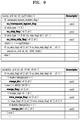
- FIG. 9 illustrates a syntax for signalling intra merge information, according to an embodiment.
- the video decoding apparatus 100 may parse a skip flag, a merge flag, and intra merge information from a bitstream according to the syntax illustrated in FIG. 9 .
- the video decoding apparatus 100 may parse a skip flag “cu_skip_flag[ ][ ]” from a coding unit syntax “coding_unit( )” and determine whether a current coding unit has been predicted in a skip mode. When the current coding unit is not predicted in the skip mode, the video decoding apparatus 100 may parse an intra skip flag “intra_skip_flag[ ][ ]” from the coding unit syntax “coding_unit( )” and determine whether the current coding unit has been predicted in an intra skip mode.
- the video decoding apparatus 100 may call a prediction unit syntax “prediction_unit( )”, parse a merge candidate index “merge_idx[ ][ ]” from a prediction unit syntax “prediction_unit( )”, and select one candidate indicated by a merge candidate index “merge_idx [ ]” in a merge candidate list when the current coding unit is decoded in the skip mode or the intra skip mode.
- the video decoding apparatus 100 may call a prediction unit syntax “prediction_unit ( )”, parse a merge flag “merge_flag[ ][ ]” from a prediction unit syntax “prediction_unit( )” when the current coding unit is decoded in an inter mode, and determine whether the current prediction unit is decoded in an inter merge mode using only an inter merge candidate.
- the video decoding apparatus 100 may further parse an intra merge flag “intra_merge_flag[ ][ ]” and determine whether the current prediction unit is decoded in the merge mode capable of using the intra merge candidate.
- the video decoding apparatus 100 may further parse a merge candidate index “merge_idx[ ][ ]” from a prediction unit syntax “prediction_unit( )”, and select one candidate indicated by a merge candidate index “merge_idx[ ]” in a merge candidate list.
- the candidate indicated by the merge candidate index may be one of the inter merge candidate, the intra merge candidate, and the inter-intra merge candidate.
- the motion vector of the current block is not defined as a result of predicting the current block.
- the motion vector of the current block has to be referred to when a motion vector prediction for a next block is performed, but the motion vector of the current block is in an unavailable state. Therefore, after the video decoding apparatus 100 according to the embodiment determines the prediction block of the current block by performing prediction on the current block in the intra mode or the intra skip mode using the intra merge candidate, the video decoding apparatus 100 may set the motion vector of the current block for the motion vector prediction of the next block to the zero vector or the motion vector of the neighboring block.
- the block may be a coding unit, a sub-block of a coding unit, or a data unit such as a largest coding unit.
- the sub-block may be a prediction unit that is a block determined by dividing a coding unit so as to perform prediction on the coding unit, a transformation unit determined by dividing a coding unit so as to perform transformation and quantization on the coding unit, and the like.
- FIG. 10 illustrates processes of determining at least one coding unit as the video decoding apparatus 100 splits a current coding unit, according to an embodiment.
- the video decoding apparatus 100 may determine a shape of a coding unit by using block shape information, and determine a shape into which a coding unit is split by using split shape information.
- a split configuration of a coding unit, which is indicated by the split shape information may be determined based on a block shape indicated by the block shape information used by the video decoding apparatus 100 .
- the video decoding apparatus 100 may use block shape information indicating that a current coding unit has a square shape. For example, the video decoding apparatus 100 may determine, according to split shape information, whether to not split a square coding unit, to split the square coding unit vertically, to split the square coding unit horizontally, or to split the square coding unit into four coding units. Referring to FIG.
- the decoder 120 may not split a coding unit 1010 a having the same size as the current coding unit 1000 according to split shape information indicating non-split, or determine coding units 1010 b , 1010 c , or 1010 d based on split shape information indicating a certain split configuration.
- the video decoding apparatus 100 may determine two coding units 1010 b by splitting the current coding unit 1000 in a vertical direction based on split shape information indicating a split in a vertical direction, according to an embodiment.
- the video decoding apparatus 100 may determine two coding units 1010 c by splitting the current coding unit 1000 in a horizontal direction based on split shape information indicating a split in a horizontal direction.
- the video decoding apparatus 100 may determine four coding units 1010 d by splitting the current coding unit 1000 in vertical and horizontal directions based on split shape information indicating splitting in vertical and horizontal directions.
- a split shape into which a square coding unit may be split is not limited to the above shapes, and may include any shape indicatable by split shape information. Certain split shapes into which a square coding unit are split will now be described in detail through various embodiments.
- FIG. 11 illustrates processes of determining at least one coding unit when the video decoding apparatus 100 splits a coding unit having a non-square shape, according to an embodiment.
- the video decoding apparatus 100 may use block shape information indicating that a current coding unit has a non-square shape.
- the video decoding apparatus 100 may determine, according to split shape information, whether to not split the non-square current coding unit or to split the non-square current coding unit according to a certain configuration. Referring to FIG.
- the video decoding apparatus 100 may not split coding units 1110 or 1160 having the same size as the current coding unit 1100 or 1150 according to split shape information indicating non-split, or determine coding units 1120 a , 1120 b , 1130 a , 1130 b , 1130 c , 1170 a , 1170 b , 1180 a , 1180 b , and 1180 c based on split shape information indicating a certain split configuration.
- a certain split configuration of splitting a non-square coding unit will now be described in detail through various embodiments.
- the video decoding apparatus 100 may determine a shape into which a coding unit is split by using split shape information, and in this case, the split shape information may indicate the number of at least one coding unit generated as the coding unit is split.
- the video decoding apparatus 100 may determine two coding units 1120 a and 1120 b or 1170 a and 1170 b included in the current coding unit 1100 or 1150 by splitting the current coding unit 1100 or 1150 based on the split shape information.
- the video decoding apparatus 100 may split the current coding unit 1100 or 1150 considering locations of long sides of the current coding unit 1100 or 1150 having a non-square shape. For example, the video decoding apparatus 100 may determine a plurality of coding units by splitting the current coding unit 1100 or 1150 in a direction of splitting the long sides of the current coding unit 1100 or 1150 considering a shape of the current coding unit 1100 or 1150 .
- the video decoding apparatus 100 may determine the odd number of coding units included in the current coding unit 1100 or 1150 . For example, when split shape information indicates that the current coding unit 1100 or 1150 is split into three coding units, the video decoding apparatus 100 may split the current coding unit 1100 or 1150 into three coding units 1130 a through 1130 c or 1180 a through 1180 c . According to an embodiment, the video decoding apparatus 100 may determine the odd number of coding units included in the current coding unit 1100 or 1150 , and the sizes of the determined coding units may not be all the same.
- the size of coding unit 1130 b or 1180 b from among the determined odd number of coding units 1130 a through 1130 c or 1180 a through 1180 c may be different from the sizes of coding units 1130 a and 1130 c or 1180 a and 1180 c .
- coding units that may be determined when the current coding unit 1100 or 1150 is split may have a plurality of types of sizes, and in some cases, the coding units 1130 a through 1130 c or 1180 a through 1180 c may have different sizes.
- the video decoding apparatus 100 may determine the odd number of coding units included in the current coding unit 1100 or 1150 , and in addition, may set a certain limit on at least one coding unit from among the odd number of coding units generated via splitting. Referring to FIG. 11 , the video decoding apparatus 100 may differentiate decoding processes performed on the coding unit 1130 b or 1180 b located at the center from among the three coding units 1130 a through 1130 c or 1180 a through 1180 c generated as the current coding unit 1100 or 1150 is split from the other coding units 1130 a and 1130 c or 1180 a and 1180 c .
- the video decoding apparatus 100 may limit the coding unit 1130 b or 1180 b located at the center to be no longer split unlike the other coding units 1130 a and 1130 c or 1180 a and 1180 c , or to be split only a certain number of times.
- FIG. 12 illustrates processes of the video decoding apparatus 100 splitting a coding unit, based on at least one of a block shape information and split shape information, according to an embodiment.
- the video decoding apparatus 100 may determine that a first coding unit 1200 having a square shape is split or not split into coding units, based on at least one of block shape information and split shape information. According to an embodiment, when split shape information indicates that the first coding unit 1200 is split in a horizontal direction, the video decoding apparatus 100 may determine a second coding unit 1210 by splitting the first coding unit 1200 in a horizontal direction.
- a first coding unit, a second coding unit, and a third coding unit used according to an embodiment are terms used to indicate a relation between before and after splitting a coding unit.
- a second coding unit may be determined by splitting a first coding unit
- a third coding unit may be determined by splitting a second coding unit.
- the video decoding apparatus 100 may determine that the determined second coding unit 1210 is split or not split into coding units based on at least one of block shape information and split shape information. Referring to FIG. 12 , the video decoding apparatus 100 may split the second coding unit 1210 , which has a non-square shape and is determined by splitting the first coding unit 1200 , into at least one third coding unit 1210 a , 1220 b , 1220 c , or 1220 d , or may not split the second coding unit 1210 , based on at least one of block shape information and split shape information.
- the video decoding apparatus 100 may obtain at least one of the block shape information and the split shape information, and obtain a plurality of second coding units (for example, the second coding units 1210 ) having various shapes by splitting the first coding unit 1200 based on at least one of the obtained block shape information and split shape information, wherein the second coding unit 1210 may be split according to a method of splitting the first coding unit 1200 based on at least one of the block shape information and the split shape information.
- a plurality of second coding units for example, the second coding units 1210 having various shapes by splitting the first coding unit 1200 based on at least one of the obtained block shape information and split shape information, wherein the second coding unit 1210 may be split according to a method of splitting the first coding unit 1200 based on at least one of the block shape information and the split shape information.
- the second coding unit 1210 may also be split into third coding units (for example, the third coding units 1220 a through 1220 d ) based on at least one of block shape information and split shape information with respect to the second coding unit 1210 .
- a coding unit may be recursively split based on at least one of split shape information and block shape information related to each coding unit.
- a square coding unit may be determined from a non-square coding unit, and such a square coding unit may be recursively split such that a non-square coding unit is determined.
- a certain coding unit for example, a coding unit located at the center or a square coding unit
- the third coding unit 1220 c having a square shape from among the third coding units 1220 b through 1220 d may be split in a horizontal direction into a plurality of fourth coding units.
- a fourth coding unit having a non-square shape from among the plurality of fourth coding units may again be split into a plurality of coding units.
- the fourth coding unit 1240 having a non-square shape may be split into an odd number of coding units.
- the video decoding apparatus 100 may determine that each of the third coding units 1220 a through 1220 d is split into coding units or that the second coding unit 1210 is not split, based on at least one of block shape information and split shape information.
- the video decoding apparatus 100 may split the second coding unit 1210 having a non-square shape into the odd number of third coding units 1220 b through 1220 d , according to an embodiment.
- the video decoding apparatus 100 may set a certain limit on a certain third coding unit from among the third coding units 1220 b through 1220 d .
- the video decoding apparatus 100 may limit that the third coding unit 1220 c located at the center of the third coding units 1220 b through 1220 d is no longer split, or is split into a settable number of times.
- the video decoding apparatus 100 may limit that the third coding unit 1220 c located at the center of the third coding units 1220 b through 1220 d included in the second coding unit 1210 having a non-square shape is no longer split, is split into a certain split shape (for example, split into four coding units or split into shapes corresponding to those into which the second coding unit 1210 is split), or is split only a certain number of times (for example, split only n times wherein n>0).
- the video decoding apparatus 100 may obtain at least one of block shape information and split shape information used to split a current coding unit from a certain location in the current coding unit.
- FIG. 13 illustrates a method of determining, by the video decoding apparatus 100 , a certain coding unit from among an odd number of coding units, according to an embodiment.
- at least one of block shape information and split shape information of a current coding unit 1300 may be obtained from a sample at a certain location (for example, a sample 1340 located at the center) from among a plurality of samples included in the current coding unit 1300 .
- the certain location in the current coding unit 1300 from which at least one of block shape information and split shape information is obtained is not limited to the center location shown in FIG.
- the video decoding apparatus 100 may determine that a current coding unit is split into coding units having various shapes and sizes or is not split by obtaining at least one of block shape information and split shape information from a certain location.
- the video decoding apparatus 100 may select one coding unit when a current coding unit is split into a certain number of coding units.
- a method of selecting one of a plurality of coding units may vary, and details thereof will be described below through various embodiments.
- the video decoding apparatus 100 may split a current coding unit into a plurality of coding units, and determine a coding unit at a certain location.
- FIG. 13 illustrates a method of determining, by the video decoding apparatus 100 , a coding unit at a certain location from among an odd number of coding units, according to an embodiment.
- the video decoding apparatus 100 may use information indicating a location of each of the odd number of coding units so as to determine a coding unit located at the center from among the odd number of coding units. Referring to FIG. 13 , the video decoding apparatus 100 may determine the odd number of coding units 1320 a through 1320 c by splitting the current coding unit 1300 . The video decoding apparatus 100 may determine the center coding unit 1320 b by using information about the locations of the odd number of coding units 1320 a through 1320 c .
- the video decoding apparatus 100 may determine the coding unit 1320 b located at the center by determining the locations of the coding units 1320 a through 1320 b based on information indicating locations of certain samples included in the coding units 1320 a through 1320 c .
- the video decoding apparatus 100 may determine the coding unit 1320 b located at the center by determining the locations of the coding units 1320 a through 1320 c based on information indicating locations of upper left samples 1330 a through 1330 c of the coding units 1320 a through 1320 c.
- the information indicating the locations of the upper left samples 1330 a through 1330 c included in the coding units 1320 a through 1320 c respectively may include information about a location or coordinates of the coding units 1320 a through 1320 c in a picture.
- the information indicating the locations of the upper left samples 1330 a through 1330 c included in the coding units 1320 a through 1320 c respectively may include information indicating widths or heights of the coding units 1320 a through 1320 c included in the current coding unit 1300 , and such widths or heights may correspond to information indicating differences between coordinates of the coding units 1320 a through 1320 c in a picture.
- the video decoding apparatus 100 may determine the coding unit 1320 b located at the center by directly using the information about the locations or coordinates of the coding units 1320 a through 1320 c in a picture or by using information about the widths or heights of the coding units 1320 a through 1320 c corresponding to the differences between coordinates.
- the information indicating the location of the upper left sample 1330 a of the upper coding unit 1320 a may indicate (xa, ya) coordinates
- the information indicating the location of the upper left sample 1330 b of the center coding unit 1320 b may indicate (xb, yb) coordinates
- the information indicating the location of the upper left sample 1330 c of the lower coding unit 1320 c may indicate (xc, yc) coordinates.
- the video decoding apparatus 100 may determine the center coding unit 1320 b by using the coordinates of the upper left samples 1330 a through 1330 c respectively included in the coding units 1320 a through 1320 c .
- the coding unit 1320 b including the coordinates (xb, yb) of the sample 1330 b located at the center may be determined as a coding unit located at the center from among the coding units 1320 a through 1320 c determined when the current coding unit 1300 is split.
- coordinates indicating the locations of the upper left samples 1330 a through 1330 c may be coordinates indicating absolute locations in a picture, and in addition, (dxb, dyb) coordinates, i.e., information indicating a relative location of the upper left sample 1330 b of the center coding unit 1320 b , and (dxc, dyc) coordinates, i.e., information indicating a relative location of the upper left sample 1330 c of the lower coding unit 1320 c , may be used based on the location of the upper left sample 1330 a of the upper coding unit 1320 a .
- a method of determining a coding unit at a certain location by using, as information indicating locations of samples included in coding units, coordinates of the samples is not limited to the above, and various arithmetic methods capable of using coordinates of samples may be used.
- the video decoding apparatus 100 may split the current coding unit 1300 into the plurality of coding units 1320 a through 1320 c , and select a coding unit from the coding units 1320 a through 1320 c according to a certain standard. For example, the video decoding apparatus 100 may select the coding unit 1320 b having a different size from among the coding units 1320 a through 1320 c.
- the video decoding apparatus 100 may determine widths or heights of the coding units 1320 a through 1320 c by respectively using the (xa, ya) coordinates, i.e., the information indicating the location of the upper left sample 1330 a of the upper coding unit 1320 a , the (xb, yb) coordinates, i.e., the information indicating the location of the upper left sample 1330 b of the center coding unit 1320 b , and the (xc, yc) coordinates, i.e., the information indicating the location of the upper left sample 1330 c of the lower coding unit 1320 c .
- the video decoding apparatus 100 may determine the sizes of the coding units 1320 a through 1320 c by respectively using the coordinates (xa, ya), (xb, yb), and (xc, yc) indicating the locations of the coding units 1320 a through 1320 c.
- the video decoding apparatus 100 may determine the width of the upper coding unit 1320 a to be xb-xa, and the height to be yb-ya. According to an embodiment, the video decoding apparatus 100 may determine the width of the center coding unit 1320 b to be xc-xb, and the height to be yc-yb. According to an embodiment, the video decoding apparatus 100 may determine the width or height of the lower coding unit 1320 c by using the width and height of the current coding unit 1300 and the widths and heights of the upper coding unit 1320 a and center coding unit 1320 b .
- the video decoding apparatus 100 may determine a coding unit having a different size from other coding units based on the determined widths and heights of the coding units 1320 a through 1320 c . Referring to FIG. 13 , the video decoding apparatus 100 may determine the center coding unit 1320 b having a size different from those of the upper coding unit 1320 a and lower coding unit 1320 c as a coding unit at a certain location.
- processes of the video decoding apparatus 100 determining a coding unit having a different size from other coding units are only an example of determining a coding unit at a certain location by using sizes of coding units determined based on sample coordinates, and thus various processes of determining a coding unit at a certain location by comparing sizes of coding units determined according to certain sample coordinates may be used.
- a location of a sample considered to determine a location of a coding unit is not limited to the upper left as described above, and information about a location of an arbitrary sample included in a coding unit may be used.
- the video decoding apparatus 100 may select a coding unit at a certain location from among an odd number of coding units determined when a current coding unit is split, while considering a shape of the current coding unit. For example, when the current coding unit has a non-square shape in which a width is longer than a height, the video decoding apparatus 100 may determine a coding unit at a certain location in a horizontal direction. In other words, the video decoding apparatus 100 may determine one of coding units having a different location in the horizontal direction and set a limit on the one coding unit.
- the video decoding apparatus 100 may determine a coding unit at a certain location in a vertical direction. In other words, the video decoding apparatus 100 may determine one of coding units having a different location in the vertical direction and set a limit on the one coding unit.
- the video decoding apparatus 100 may use information indicating a location of each of an even number of coding units so as to determine a coding unit at a certain location from among the even number of coding units.
- the video decoding apparatus 100 may determine the even number of coding units by splitting a current coding unit, and determine the coding unit at the certain location by using information about the locations of the even number of coding units.
- Detailed processes thereof may correspond to those of determining a coding unit at a certain location (for example, a center location) from among an odd number of coding units described in FIG. 13 , and thus details thereof are not provided again.
- certain information about a coding unit at a certain location during splitting processes may be used to determine the coding unit at the certain location from among the plurality of coding units.
- the video decoding apparatus 100 may use at least one of block shape information and split shape information stored in a sample included in a center coding unit during splitting processes so as to determine a coding unit located at the center from among a plurality of coding units obtained by splitting a current coding unit.
- the video decoding apparatus 100 may split the current coding unit 1300 into the plurality of coding units 1320 a through 1320 c based on at least one of block shape information and split shape information, and determine the coding unit 1320 b located at the center from among the plurality of coding units 1320 a through 1320 c . In addition, the video decoding apparatus 100 may determine the coding unit 1320 b located at the center considering a location from which at least one of the block shape information and the split shape information is obtained.
- At least one of the block shape information and the split shape information of the current coding unit 1300 may be obtained from the sample 1340 located at the center of the current coding unit 1300 , and when the current coding unit 1300 is split into the plurality of coding units 1320 a through 1320 c based on at least one of the block shape information and the split shape information, the coding unit 1320 b including the sample 1340 may be determined as a coding unit located at the center.
- information used to determine a coding unit located at the center is not limited to at least one of the block shape information and the split shape information, and various types of information may be used while determining a coding unit located at the center.
- certain information for identifying a coding unit at a certain location may be obtained from a certain sample included in a coding unit to be determined.
- the video decoding apparatus 100 may use at least one of block shape information and split shape information obtained from a sample at a certain location in the current coding unit 1300 (for example, a sample located at the center of the current coding unit 1300 ), so as to determine a coding unit at a certain location (for example, a coding unit located at the center from among a plurality of coding units) from among the plurality of coding units 1320 a through 1320 c determined when the current coding unit 1300 is split.
- the video decoding apparatus 100 may determine the sample at the certain location considering a block shape of the current coding unit 1300 , and determine and set a certain limit on the coding unit 1320 b including a sample from which certain information (for example, at least one of block shape information and split shape information) is obtainable, from among the plurality of coding units 1320 a through 1320 c determined when the current coding unit 1300 is split.
- the video decoding apparatus 100 may determine, as a sample from which certain information is obtainable, the sample 1340 located at the center of the current coding unit 1300 , and set a certain limit on the coding unit 1320 b including such a sample 1340 during decoding processes.
- a location of a sample from which certain information is obtainable is not limited to the above, and may be a sample at an arbitrary location included in the coding unit 1320 b determined to set a limit.
- a location of a sample from which certain information is obtainable may be determined according to a shape of the current coding unit 1300 .
- block shape information may determine whether a shape of a current coding unit is square or non-square, and determine a location of a sample from which certain information is obtainable according to the shape.
- the video decoding apparatus 100 may determine, as a sample from which certain information is obtainable, a sample located on a boundary of splitting at least one of a width and a height of a current coding unit into halves by using at least one of information about the width of the current coding unit and information about the height of the current coding unit.
- the video decoding apparatus 100 may determine, as a sample from which certain information is obtainable, one of samples adjacent to a boundary of splitting long sides of the current coding unit into halves.
- the video decoding apparatus 100 may use at least one of block shape information and split shape information so as to determine a coding unit at a certain location from among the plurality of coding units.
- the video decoding apparatus 100 may obtain at least one of block shape information and split shape information from a sample at a certain location included in a coding unit, and may split a plurality of coding units generated as a current coding unit is split by using at least one of the split shape information and the block shape information obtained from the sample at the certain location included in each of the plurality of coding units.
- a coding unit may be recursively split by using at least one of block shape information and split shape information obtained from a sample at a certain location included in each coding unit. Since processes of recursively splitting a coding unit have been described above with reference to FIG. 12 , details thereof are not provided again.
- the video decoding apparatus 100 may determine at least one coding unit by splitting a current coding unit, and determine an order of decoding the at least one coding unit according to a certain block (for example, the current coding unit).
- FIG. 14 illustrates an order of processing a plurality of coding units when the plurality of coding units are determined when the video decoding apparatus 100 splits a current coding unit, according to an embodiment.
- the video decoding apparatus 100 may determine second coding units 1410 a and 1410 b by splitting a first coding unit 1400 in a vertical direction, determine second coding units 1430 a and 1430 b by splitting the first coding unit 1400 in a horizontal direction, or determine second coding units 1450 a through 1450 d by splitting the first coding unit 140 in horizontal and vertical directions, according to block shape information and split shape information.
- the video decoding apparatus 100 may determine the second coding units 1410 a and 1410 b , which are determined by splitting the first coding unit 1400 in the vertical direction, to be processed in a horizontal direction 1410 c .
- the video decoding apparatus 100 may determine the second coding units 1430 a and 1430 b , which are determined by splitting the first coding unit 1400 in the horizontal direction, to be processed in a vertical direction 1430 c .
- the video decoding apparatus 100 may determine the second coding units 1450 a through 1450 d , which are determined by splitting the first coding unit 1400 in the vertical and horizontal directions to be processed according to a certain order in which coding units located in one row is processed and then coding units located in a next row is processed (for example, a raster scan order or a z-scan order 1450 e ).
- the video decoding apparatus 100 may recursively split coding units. Referring to FIG. 14 , the video decoding apparatus 100 may determine the plurality of second coding units 1410 a and 1410 b , 1430 a and 1430 b , or 1450 a through 1450 d by splitting the first coding unit 1400 , and recursively split each of the plurality of second coding units 1410 a and 1410 b , 1430 a and 1430 b , or 1450 a through 1450 d .
- a method of splitting the plurality of second coding units 1410 a and 1410 b , 1430 a and 1430 b , or 1450 a through 1450 d may correspond to a method of splitting the first coding unit 1400 . Accordingly, each of the plurality of second coding units 1410 a and 1410 b , 1430 a and 1430 b , or 1450 a through 1450 d may be independently split into a plurality of coding units. Referring to FIG.
- the video decoding apparatus 100 may determine the second coding units 1410 a and 1410 b by splitting the first coding unit 1400 in the vertical direction, and in addition, determine that each of the second coding units 1410 a and 1410 b is independently split or not split.
- the video decoding apparatus 100 may split the second coding unit 1410 a at the left in a horizontal direction into third coding units 1420 a and 1420 b , and may not split the second coding unit 1410 b at the right.
- an order of processing coding units may be determined based on split processes of coding units.
- an order of processing coding units that are split may be determined based on an order of processing coding units before being split.
- the video decoding apparatus 100 may determine an order of processing the third coding units 1420 a and 1420 b determined when the second coding unit 1410 a at the left is split independently from the second coding unit 1410 b at the right. Since the third coding units 1420 a and 1420 b are determined when the second coding unit 1410 a at the left is split in a horizontal direction, the third coding units 1420 a and 1420 b may be processed in a vertical direction 1420 c .
- the second coding unit 1410 b at the right may be processed after the third coding units 1420 a and 1420 b included in the second coding unit 1410 a at the left are processed in the vertical direction 1420 c .
- the above descriptions are related processes of determining an order of processing coding units according to coding units before being split, but such processes are not limited to the above embodiments, and any method of independently processing, in a certain order, coding units split into various shapes may be used.
- FIG. 15 illustrates processes of determining that a current coding unit is split into an odd number of coding units when a coding unit is not processable in a certain order by the video decoding apparatus 100 , according to an embodiment.
- the video decoding apparatus 100 may determine that a current coding unit is split into an odd number of coding units based on obtained block shape information and split shape information.
- a first coding unit 1500 having a square shape may be split into second coding units 1510 a and 1510 b having a non-square shape, and the second coding units 1510 a and 1510 b may be independently respectively split into third coding units 1520 a and 1520 b , and 1520 c through 1520 e .
- the video decoding apparatus 100 may split the second coding unit 1510 a at the left from among the second coding units 1510 a and 1510 b into a horizontal direction to determine the plurality of third coding units 1520 a and 1520 b , and split the second coding unit 1510 b at the right into the odd number of third coding units 1520 c through 1520 e.
- the video decoding apparatus 100 may determine whether a coding unit split into an odd number exists by determining whether the third coding units 1520 a through 1520 e are processable in a certain order. Referring to FIG. 15 , the video decoding apparatus 100 may determine the third coding units 1520 a through 1520 e by recursively splitting the first coding unit 1500 . The video decoding apparatus 100 may determine, based on at least one of block shape information and split shape information, whether a coding unit is split into an odd number from among shapes into which the first coding unit 1500 , the second coding units 1510 a and 1510 b , or the third coding units 1520 a through 1520 e are split.
- the second coding unit 1510 b at the right from among the second coding units 1510 a and 1510 b may be split into the odd number of third coding units 1520 c through 1520 e .
- An order of processing a plurality of coding units included in the first coding unit 1500 may be a certain order (for example, a z-scan order 1530 ), and the video decoding apparatus 100 may determine whether the third coding units 1520 c through 1520 e determined when the second coding unit 1510 b at the right is split into an odd number satisfy a condition of being processable according to the certain order.
- the video decoding apparatus 100 may determine whether the third coding units 1520 a through 1520 e included in the first coding unit 1500 satisfy a condition of being processable according to a certain order, wherein the condition is related to whether at least one of a width and a height of each of the second coding units 1510 a and 1510 b is split into halves according to boundaries of the third coding units 1520 a through 1520 e .
- the third coding units 1520 a and 1520 b determined when the height of the second coding unit 1510 a at the left and having a non-square shape is split into halves satisfy the condition, but it may be determined that the third coding units 1520 c through 1520 e do not satisfy the condition because the boundaries of the third coding units 1520 c through 1520 e that are determined when the second coding unit 1510 b at the right is split into three coding units do not split the width or height of the second coding unit 1510 b at the right into halves.
- the video decoding apparatus 100 may determine disconnection of a scan order when the condition is not satisfied, and determine that the second coding unit 1510 b at the right is split into the odd number of coding units, based on a result of the determination. According to an embodiment, the video decoding apparatus 100 may set a certain limit on a coding unit at a certain location from among an odd number of coding units obtained by splitting a coding unit, and since such a limit or certain location has been described above through various embodiments, details thereof are not provided again.
- FIG. 16 illustrates processes of determining at least one coding unit when the video decoding apparatus 100 splits a first coding unit 1600 , according to an embodiment.
- the video decoding apparatus 100 may split the first coding unit 1600 based on at least one of block shape information and split shape information.
- the first coding unit 1600 having a square shape may be split into four coding units having a square shape or a plurality of coding units having a non-square shape.
- block shape information indicates that the first coding unit 1600 is a square and split shape information indicates a split into non-square coding units
- the video decoding apparatus 100 may split the first coding unit 1600 into a plurality of non-square coding units.
- the video decoding apparatus 100 may determine, as the odd number of coding units, second coding units 1610 a through 1610 c by splitting the first coding unit 1600 having a square shape in a vertical direction, or second coding units 1620 a through 1620 c by splitting the first coding unit 1600 in a horizontal direction.
- the video decoding apparatus 100 may determine whether the second coding units 1610 a through 1610 c and 1620 a through 1620 c included in the first coding unit 1600 satisfy a condition of being processable in a certain order, wherein the condition is related to whether at least one of a width and a height of the first coding unit 1600 is split into halves according to boundaries of the second coding units 1610 a through 1610 c and 1620 a through 1620 c .
- the first coding unit 1600 does not satisfy the condition of being processable in a certain order. Also, since the boundaries of the second coding units 1620 a through 1620 c determined when the first coding unit 1600 having a square shape is split in a horizontal direction do not split the height of the first coding unit 1600 into halves, it may be determined that the first coding unit 1600 does not satisfy the condition of being processable in a certain order.
- the video decoding apparatus 100 may determine disconnection of a scan order when the condition is not satisfied, and determine that the first coding unit 1600 is split into the odd number of coding units based on a result of the determination. According to an embodiment, the video decoding apparatus 100 may set a certain limit on a coding unit at a certain location from among an odd number of coding units obtained by splitting a coding unit, and since such a limit or certain location has been described above through various embodiments, details thereof are not provided again.
- the video decoding apparatus 100 may determine coding units having various shapes by splitting a first coding unit.
- the video decoding apparatus 100 may split the first coding unit 1600 having a square shape and a first coding unit 1630 or 1650 having a non-square shape into coding units having various shapes.
- FIG. 17 illustrates that a shape into which a second coding unit is splittable by the video decoding apparatus 100 is restricted when the second coding unit having a non-square shape determined when a first coding unit 1700 is split satisfies a certain condition, according to an embodiment.
- the video decoding apparatus 100 may determine that the first coding unit 1700 having a square shape is split into second coding units 1710 a and 1710 b or 1720 a and 1720 b having a non-square shape, based on at least one of block shape information and split shape information.
- the second coding units 1710 a and 1710 b or 1720 a and 1720 b may be independently split.
- the video decoding apparatus 100 may determine that the second coding units 1710 a and 1710 b or 1720 a and 1720 b are split into a plurality of coding units or are not split based on at least one of block shape information and split shape information related to each of the coding units 1710 a and 1710 b or 1720 a and 1720 b .
- the video decoding apparatus 100 may determine third coding units 1712 a and 1712 b by splitting, in a horizontal direction, the second coding unit 1710 a at the left having a non-square shape, which is determined when the first coding unit 1700 is split in a vertical direction.
- the video decoding apparatus 100 may set a limit that the second coding unit 1710 b at the right is not split in the horizontal direction like the second coding unit 1710 a at the left.
- third coding units 1714 a and 1714 b are determined when the second coding unit 1710 b at the right is split in the same direction, i.e., the horizontal direction
- the third coding units 1712 a , 1712 b , 1714 a , and 1714 b are determined when the second coding units 1710 a at the left and the second coding unit 1710 b at the right are each independently split in the horizontal direction.
- the video decoding apparatus 100 may determine third coding units 1722 a and 1722 b or 1724 a , and 1724 b by splitting, in a vertical direction, the second coding unit 1720 a or 1720 b having a non-square shape determined when the first coding unit 1700 is split in the horizontal direction.
- the video decoding apparatus 100 may set a limit that the other second coding unit (for example, the second coding unit 1720 b at the bottom) is not split in the vertical direction like the second coding unit 1720 a at the top for the above described reasons.
- FIG. 18 illustrates processes of the video decoding apparatus 100 splitting a coding unit having a square shape when split shape information is unable to indicate that a coding unit is split into four square shapes, according to an embodiment.
- the video decoding apparatus 100 may determine second coding units 1810 a and 1810 b , or 1820 a and 1820 b , by splitting a first coding unit 1800 based on at least one of block shape information and split shape information.
- Split shape information may include information about various shapes into which a coding unit may be split, but such information about various shapes may not include information for splitting a coding unit into four square coding units.
- the video decoding apparatus 100 is unable to split the first coding unit 1800 having a square shape into four second coding units 1830 through 1830 d having a square shape.
- the video decoding apparatus 100 may determine the second coding units 1810 a and 1810 b , or 1820 a and 1820 b having a non-square shape based on the split shape information.
- the video decoding apparatus 100 may independently split each of the second coding units 1810 a and 1810 b , or 1820 a and 1820 b having a non-square shape.
- Each of the second coding units 1810 a and 1810 b , or 1820 a and 1820 b may be split in a certain order via a recursive method that may be a split configuration corresponding to a method of splitting the first coding unit 1800 based on at least one of the block shape information and the split shape information.
- the video decoding apparatus 100 may determine third coding units 1812 a and 1812 b having a square shape by splitting the second coding unit 1810 a at the left in a horizontal direction, or determine third coding units 1814 a and 1814 b having a square shape by splitting the second coding unit 1810 b at the right in a horizontal direction.
- the video decoding apparatus 100 may determine third coding units 1816 a through 1816 d having a square shape by splitting both the second coding unit 1810 a at the left and the second coding unit 1810 b at the right in the horizontal direction.
- coding units may be determined in the same manner as when the first coding unit 1800 is split into four second coding units 1830 a through 1830 d having a square shape.
- the video decoding apparatus 100 may determine third coding units 1822 a and 1822 b having a square shape by splitting the second coding unit 1820 a at the top in a vertical direction, and determine third coding units 1824 a and 1824 b having a square shape by splitting the second coding unit 1820 b at the bottom in a vertical direction.
- the video decoding apparatus 100 may determine third coding units 1826 a through 1826 d having a square shape by splitting both the second coding unit 1820 a at the top and the second coding unit 1820 b at the bottom in the vertical direction.
- coding units may be determined in the same manner as when the first coding unit 1800 is split into four second coding units 1830 a through 1830 d having a square shape.
- FIG. 19 illustrates that an order of processing a plurality of coding units may be changed according to processes of splitting a coding unit, according to an embodiment.
- the video decoding apparatus 100 may split a first coding unit 1900 based on block shape information and split shape information.
- the block shape information indicates a square shape and the split shape information indicates that the first coding unit 1900 is split in at least one of a horizontal direction and a vertical direction
- the video decoding apparatus 100 may split the first coding unit 1900 to determine second coding units 1910 a and 1910 b , or 1920 a and 1920 b .
- the second coding units 1910 a and 1910 b , or 1920 a and 1920 b having a non-square shape and determined when the first coding unit 1900 is split in the horizontal direction or the vertical direction may each be independently split based on block shape information and split shape information.
- the video decoding apparatus 100 may determine third coding units 1916 a through 1916 d by splitting, in the horizontal direction, each of the second coding units 1910 a and 1910 b generated as the first coding unit 1900 is split in the vertical direction, or determine third coding units 1926 a through 1926 d by splitting, in the horizontal direction, the second coding units 1920 a and 1920 b generated as the first coding unit 1900 is split in the vertical direction.
- Processes of splitting the second coding units 1910 a and 1910 b , or 1920 a and 1920 b have been described above with reference to FIG. 17 , and thus details thereof are not provided again.
- the video decoding apparatus 100 may process coding units according to a certain order. Features about processing coding units according to a certain order have been described above with reference to FIG. 14 , and thus details thereof are not provided again. Referring to FIG. 19 , the video decoding apparatus 100 may determine four third coding units 1916 a through 1916 d or 1926 a through 1926 d having a square shape by splitting the first coding unit 1900 having a square shape. According to an embodiment, the video decoding apparatus 100 may determine an order of processing the third coding units 1916 a through 1916 d or 1926 a through 1926 d based on how the first coding unit 1900 is split.
- the video decoding apparatus 100 may determine the third coding units 1916 a through 1916 d by splitting, in the horizontal direction, the second coding units 1910 a and 1910 b generated as the first coding unit 1900 is split in the vertical direction, and process the third coding units 1916 a through 1916 d according to an order 1917 of first processing, in the vertical direction, the third coding units 1916 a and 1916 b included in the second coding unit 1910 a at the left, and then processing, in the vertical direction, the third coding units 1916 c and 1916 d included in the second coding unit 1910 b at the right.
- the video decoding apparatus 100 may determine the third coding units 1926 a through 1926 d by splitting, in the vertical direction, the second coding units 1920 a and 1920 b generated as the first coding unit 1900 is split in the horizontal direction, and process the third coding units 1926 a through 1926 d according to an order 1927 of first processing, in the horizontal direction, the third coding units 1926 a and 1926 b included in the second coding unit 1920 a at the top, and then processing, in the horizontal direction, the third coding units 1926 c and 1926 d included in the second coding unit 1920 b at the bottom.
- the third coding units 1916 a through 1916 d or 1926 a through 1926 d having a square shape may be determined when the second coding units 1910 a and 1910 b , or 1920 a and 1920 b are each split.
- the second coding units 1910 a and 1910 b determined when the first coding unit 1900 is split in the vertical direction and the second coding units 1920 a and 1920 b determined when the first coding unit 1900 is split in the horizontal direction are split in different shapes, but according to the third coding units 1916 a through 1916 d and 1926 a through 1926 d determined afterwards, the first coding unit 1900 is split in coding units having same shapes.
- the video decoding apparatus 100 may process pluralities of coding units determined in same shapes in different orders even when the coding units having the same shapes are consequently determined when coding units are recursively split through different processes based on at least one of block shape information and split shape information.
- FIG. 20 illustrates processes of determining a depth of a coding unit as a shape and size of the coding unit are changed, when a plurality of coding units are determined when the coding unit is recursively split, according to an embodiment.
- the video decoding apparatus 100 may determine a depth of a coding unit according to a certain standard.
- the certain standard may be a length of a long side of the coding unit.
- a length of a long side of a current coding unit is split 2 n times shorter than a length of a long side of a coding unit before being split, it may be determined that a depth of the current coding unit is increased n times a depth of the coding unit before being split, wherein n>0.
- a coding unit having an increased depth is referred to as a coding unit of a lower depth.
- the video decoding apparatus 100 may determine a second coding unit 2002 and a third coding unit 2004 of lower depths by splitting a first coding unit 2000 having a square shape, based on block shape information indicating a square shape (for example, block shape information may indicate ‘0:SQURE’), according to an embodiment.
- block shape information for example, block shape information may indicate ‘0:SQURE’
- the second coding unit 2002 determined by splitting a width and a height of the first coding unit 2000 by 1/21 may have a size of N ⁇ N.
- the third coding unit 2004 determined by splitting a width and a height of the second coding unit 2002 by 1 ⁇ 2 may have a size of N/2 ⁇ N/2.
- a width and a height of the third coding unit 2004 corresponds to 1 ⁇ 2 of the first coding unit 2000 .
- a depth of first coding unit 2000 is D
- a depth of the second coding unit 2002 having 1/21 of the width and the height of the first coding unit 2000 may be D+1
- a depth of the third coding unit 2004 having 1 ⁇ 2 of the width and the height of the first coding unit 2000 may be D+2.
- the video decoding apparatus 100 may determine a second coding unit 2012 or 2022 and a third coding unit 2014 or 2024 by splitting a first coding unit 2010 or 2020 having a non-square shape, based on block shape information indicating a non-square shape (for example, block shape information may indicate ‘1:NS_VER’ indicating a non-square shape in which a height is longer than a width, or ‘2:NS_HOR’ indicating a non-square shape in which a width is longer than a height), according to an embodiment.
- block shape information may indicate ‘1:NS_VER’ indicating a non-square shape in which a height is longer than a width, or ‘2:NS_HOR’ indicating a non-square shape in which a width is longer than a height
- the video decoding apparatus 100 may determine a second coding unit (for example, the second coding unit 2002 , 2012 , or 2022 ) by splitting at least one of a width and a height of the first coding unit 2010 having a size of N ⁇ 2N.
- the video decoding apparatus 100 may determine the second coding unit 2002 having a size of N ⁇ N or the second coding unit 2022 having a size of N ⁇ N/2 by splitting the first coding unit 2010 in a horizontal direction, or determine the second coding unit 2012 having a size of N/2 ⁇ N by splitting the first coding unit 2010 in horizontal and vertical directions.
- the video decoding apparatus 100 may determine a second coding unit (for example, the second coding unit 2002 , 2012 , or 2022 ) by splitting at least one of a width and a height of the first coding unit 2020 having a size of 2N ⁇ N.
- the video decoding apparatus 100 may determine the second coding unit 2002 having a size of N ⁇ N or the second coding unit 2012 having a size of N/2 ⁇ N by splitting the first coding unit 200 in a vertical direction, or determine the second coding unit 2022 having a size of N ⁇ N/2 by splitting the first coding unit 2010 in horizontal and vertical directions.
- the video decoding apparatus 100 may determine a third coding unit (for example, the third coding unit 2004 , 2014 , or 2024 ) by splitting at least one of a width and a height of the second coding unit 2002 having a size of N ⁇ N.
- the video decoding apparatus 100 may determine the third coding unit 2004 having a size of N/2 ⁇ N/2, the third coding unit 2014 having a size of N/22 ⁇ N/2, or the third coding unit 2024 having a size of N/2 ⁇ N/22 by splitting the second coding unit 2002 in vertical and horizontal directions.
- the video decoding apparatus 100 may determine a third coding unit (for example, the third coding unit 2004 , 2014 , or 2024 ) by splitting at least one of a width and a height of the second coding unit 2022 having a size of N/2 ⁇ N.
- the video decoding apparatus 100 may determine the third coding unit 2004 having a size of N/2 ⁇ N/2 or the third coding unit 2024 having a size of N/2 ⁇ N/22 by splitting the second coding unit 2012 in a horizontal direction, or the third coding unit 2014 having a size of N/22 ⁇ N/2 by splitting the second coding unit 2012 in vertical and horizontal directions.
- the video decoding apparatus 100 may determine a third coding unit (for example, the third coding unit 2004 , 2014 , or 2024 ) by splitting at least one of a width and a height of the second coding unit 2022 having a size of N ⁇ N/2.
- the video decoding apparatus 100 may determine the third coding unit 2004 having a size of N/2 ⁇ N/2 or the third coding unit 2014 having a size of N/22 ⁇ N/2 by splitting the second coding unit 2022 in a vertical direction, or the third coding unit 2024 having a size of N/2 ⁇ N/22 by splitting the second coding unit 2022 in vertical and horizontal directions.
- the video decoding apparatus 100 may split a coding unit (for example, the first, second, or third coding unit 2000 , 2002 , or 2004 ) having a square shape in a horizontal or vertical direction.
- a coding unit for example, the first, second, or third coding unit 2000 , 2002 , or 2004
- the first coding unit 2010 having a size of N ⁇ 2N may be determined by splitting the first coding unit 2000 having a size of 2N ⁇ 2N in the vertical direction
- the first coding unit 2020 having a size of 2N ⁇ N may be determined by splitting the first coding unit 2000 in the horizontal direction.
- a depth of a coding unit determined when the first coding unit 2000 having a size of 2N ⁇ 2N is split in a horizontal or vertical direction may be the same as a depth of the first coding unit 2000 .
- the width and the height of the third coding unit 2014 or 2024 may be 1 ⁇ 2 of those of the first coding unit 2010 or 2020 .
- the depth of the first coding unit 2010 or 2020 is D
- the depth of the second coding unit 2012 or 2022 that is 1 ⁇ 2 of the width and the height of the first coding unit 2010 or 2020 may be D+1
- the depth of the third coding unit 2014 or 2024 that is 1 ⁇ 2 of the width and the height of the first coding unit 2010 or 202 may be D+2.
- FIG. 21 illustrates a part index (PID) for distinguishing depths and coding units, which may be determined according to shapes and sizes of coding units, according to an embodiment.
- PID part index
- the video decoding apparatus 100 may determine a second coding unit having various shapes by splitting a first coding unit 2100 having a square shape. Referring to FIG. 21 , the video decoding apparatus 100 may determine second coding units 2102 a and 2102 b , 2104 a and 2104 b , or 2106 a through 2106 d by splitting the first coding unit 2100 in at least one of a vertical direction and a horizontal direction, according to split shape information. In other words, the video decoding apparatus 100 may determine the second coding units 2102 a and 2102 b , 2104 a and 2104 b , or 2106 a through 2106 d based on split shape information of the first coding unit 2100 .
- a depth of the second coding units 2102 a and 2102 b , 2104 a and 2104 b , or 2106 a through 2106 d determined according to the split shape information of the first coding unit 2100 having a square shape may be determined based on a length of a long side.
- the depths of the first coding unit 2100 and the second coding units 2102 a and 2102 b or 2104 a and 2104 b having a non-square shape may be the same, i.e., D.
- the video decoding apparatus 100 splits the first coding unit 2100 into the four second coding units 2106 a through 2106 d having a square shape, based on the split shape information, a length of one side of the second coding units 2106 a through 2106 d having a square shape is 1 ⁇ 2 of the length of one side of the first coding unit 2100 , the depths of the second coding units 2106 a through 2106 d may be D+1, i.e., a depth lower than the depth D of the first coding unit 2100 .
- the video decoding apparatus 100 may split a first coding unit 2110 , in which a height is longer than a width, in a horizontal direction into a plurality of second coding units 2112 a and 2112 b or 2114 a through 2114 c , according to split shape information.
- the video decoding apparatus 100 may split a first coding unit 2120 , in which a width is longer than a height, in a vertical direction into a plurality of second coding units 2122 a and 2122 b or 2124 a through 2124 c , according to split shape information.
- depths of the second coding units 2112 a and 2112 b , 2114 a through 2114 c , 2122 a and 2122 b , or 2124 a through 2124 c determined according to the split shape information of the first coding unit 2110 or 2120 having a non-square shape may be determined based on a length of a long side.
- the depths of the second coding units 2112 a and 2112 b are D+1, i.e., depths lower than the depth D of the first coding unit 2110 having a non-square shape.
- the video decoding apparatus 100 may split the first coding unit 2110 having a non-square shape into an odd number of second coding units 2114 a through 2114 c , based on split shape information.
- the odd number of second coding units 2114 a through 2114 c may include the second coding units 2114 a and 2114 c having a non-square shape, and the second coding unit 2114 b having a square shape.
- depths of the second coding units 2114 a through 2114 b may be D+1, i.e., a depth lower than the depth D of the first coding unit 2110 .
- the video decoding apparatus 100 may determine depths of coding units related to the first coding unit 2120 having a non-square shape in which a width is longer than a height, in the same manner as the determining of depths of coding units related to the first coding unit 2110 .
- the video decoding apparatus 100 may determine PIDs based on a size ratio of the coding units.
- the second coding unit 2114 b located at the center from the odd number of second coding units 2114 a through 2114 c may have the same width as the second coding units 2114 a and 2114 c , but have a height twice higher than those of the second coding units 2114 a and 2114 c .
- the second coding unit 2114 b located at the center may include two of the second coding units 2114 a and 2114 c .
- the PID of the second coding unit 2114 b located at the center is 1 according to a scan order
- the PID of the second coding unit 2114 c in a next order may be 3, the PID having increased by 2.
- values of the PID may be discontinuous.
- the video decoding apparatus 100 may determine whether an odd number of coding units have the same sizes based on discontinuity of PID for distinguishing the coding units.
- the video decoding apparatus 100 may determine whether a plurality of coding units determined when a current coding unit is split have certain split shapes based on values of PID. Referring to FIG. 21 , the video decoding apparatus 100 may determine the even number of second coding units 2112 a and 211 b or the odd number of second coding units 2114 a through 2114 c by splitting the first coding unit 2110 having a rectangular shape in which the height is longer than the width. The video decoding apparatus 100 may use the PID indicating each coding unit so as to distinguish a plurality of coding units. According to an embodiment, a PID may be obtained from a sample at a certain location (for example, an upper left sample) of each coding unit.
- the video decoding apparatus 100 may determine a coding unit at a certain location from among coding units determined by using PIDs for distinguishing coding units.
- the video decoding apparatus 100 may split the first coding unit 2110 into the three second coding units 2114 a through 2114 c .
- the video decoding apparatus 100 may assign a PID to each of the three second coding units 2114 a through 2114 c .
- the video decoding apparatus 100 may compare PIDs of an odd number of coding units so as to determine a center coding unit from among the coding units.
- the video decoding apparatus 100 may determine, as a coding unit at a center location from among coding units determined when the first coding unit 2110 is split, the second coding unit 2114 b having a PID corresponding to a center value from among PIDs, based on PIDs of the coding units. According to an embodiment, while determining PIDs for distinguishing coding units, when the coding units do not have the same sizes, the video decoding apparatus 100 may determine PIDs based on a size ratio of the coding units. Referring to FIG.
- the second coding unit 2114 b generated when the first coding unit 2110 is split may have the same width as the second coding units 2114 a and 2114 c , but may have a height twice higher than those of the second coding units 2114 a and 2114 c .
- the PID of the second coding unit 2114 b located at the center is 1, the PID of the second coding unit 2114 c in a next order may be 3, the PID having increased by 2.
- the video decoding apparatus 100 may determine that a current coding unit is split into a plurality of coding units including a coding unit having a different size from other coding units.
- the video decoding apparatus 100 may split a current coding unit into a plurality of coding units, in which a coding unit at a certain location (for example, a center coding unit) has a size different from other coding units.
- the video decoding apparatus 100 may determine the center coding unit having the different size by using PIDs of the coding units.
- a PID, and a size or location of a coding unit at a certain location described above are specified to describe an embodiment, and thus should not be limitedly interpreted, and various PIDs, and various locations and sizes of a coding unit may be used.
- the video decoding apparatus 100 may use a certain data unit from which recursive splitting of a coding unit is started.
- FIG. 22 illustrates that a plurality of coding units are determined according to a plurality of certain data units included in a picture, according to an embodiment.
- a certain data unit may be defined as a data unit from which a coding unit starts to be recursively split by using at least one of block shape information and split shape information.
- the certain data unit may correspond to a coding unit of an uppermost depth used while determining a plurality of coding units by splitting a current picture.
- the certain data unit is referred to as a reference data unit for convenience of description.
- the reference data unit may indicate a certain size and shape.
- the reference data unit may include M ⁇ N samples.
- M and N may be the same, and may be an integer expressed as a multiple of 2.
- a reference data unit may indicate a square shape or a non-square shape, and may later be split into an integer number of coding units.
- the video decoding apparatus 100 may split a current picture into a plurality of reference data units. According to an embodiment, the video decoding apparatus 100 may split the plurality of reference data units obtained by splitting the current picture by using split shape information about each of the reference data units. Split processes of such reference data units may correspond to split processes using a quad-tree structure.
- the video decoding apparatus 100 may pre-determine a smallest size available for the reference data unit included in the current picture. Accordingly, the video decoding apparatus 100 may determine the reference data unit having various sizes that are equal to or larger than the smallest size, and determine at least one coding unit based on the determined reference data unit by using block shape information and split shape information.
- the video decoding apparatus 100 may use a reference coding unit 2200 having a square shape, or may use a reference coding unit 2202 having a non-square shape.
- a shape and size of a reference coding unit may be determined according to various data units (for example, a sequence, a picture, a slice, a slice segment, and a largest coding unit) that may include at least one reference coding unit.
- the video decoding apparatus 100 may obtain, from a bitstream, at least one of information about a shape of a reference coding unit and information about a size of the reference coding unit, according to the various data units.
- Processes of determining at least one coding unit included in the reference coding unit 2200 having a square shape have been described above through processes of splitting the current coding unit 1000 of FIG. 10
- processes of determining at least one coding unit included in the reference coding unit 2200 having a non-square shape have been described above through processes of splitting the current coding unit 1100 or 1150 of FIG. 11 , and thus details thereof are not provided again.
- the video decoding apparatus 100 may use a PID for distinguishing the size and shape of the reference coding unit.
- the video decoding apparatus 100 may obtain, from a bitstream, only a PID for distinguishing a size and shape of a reference coding unit as a data unit satisfying a predetermined condition (for example, a data unit having a size equal to or smaller than a slice) from among various data units (for example, a sequence, a picture, a slice, a slice segment, and a largest coding unit), according to slices, slice segments, and largest coding units.
- a predetermined condition for example, a data unit having a size equal to or smaller than a slice
- various data units for example, a sequence, a picture, a slice, a slice segment, and a largest coding unit
- the video decoding apparatus 100 may determine the size and shape of the reference data unit according to data units that satisfy the predetermined condition, by using the PID.
- information about a shape of a reference coding unit and information about a size of a reference coding unit are obtained from a bitstream and used according to data units having relatively small sizes, usage efficiency of the bitstream may not be sufficient, and thus instead of directly obtaining the information about the shape of the reference coding unit and the information about the size of the reference coding unit, only a PID may be obtained and used. In this case, at least one of the size and the shape of the reference coding unit corresponding to the PID indicating the size and shape of the reference coding unit may be pre-determined.
- the video decoding apparatus 100 may select at least one of the pre-determined size and shape of the reference coding unit according to the PID so as to determine at least one of the size and shape of the reference coding unit included in a data unit that is a criterion for obtaining the PID.
- the video decoding apparatus 100 may use at least one reference coding unit included in one largest coding unit.
- a largest coding unit splitting an image may include at least one reference coding unit, and a coding unit may be determined when each of the reference coding unit is recursively split.
- at least one of a width and height of the largest coding unit may be an integer times at least one of a width and height of the reference coding unit.
- a size of a reference coding unit may be equal to a size of a largest coding unit, which is split n times according to a quad-tree structure.
- the video decoding apparatus 100 may determine a reference coding unit by splitting a largest coding unit n times according to a quad-tree structure, and split the reference coding unit based on at least one of block shape information and split shape information according to various embodiments.
- FIG. 23 illustrates a processing block serving as a criterion of determining a determination order of a reference coding unit included in a picture 2300 , according to an embodiment.
- the video decoding apparatus 100 may determine at least one processing block splitting a picture.
- a processing block is a data unit including at least one reference coding unit splitting an image, and the at least one reference coding unit included in the processing block may be determined in a certain order.
- a determining order of the at least one reference coding unit determined in each processing block may correspond to one of various orders for determining a reference coding unit, and may vary according to processing blocks.
- a determining order of reference coding units determined per processing block may be one of various orders, such as a raster scan order, a Z-scan order, an N-scan order, an up-right diagonal scan order, a horizontal scan order, and a vertical scan order, but should not be limitedly interpreted with respect to the scan orders.
- the video decoding apparatus 100 may determine a size of at least one processing block included in an image by obtaining information about a size of a processing block.
- the video decoding apparatus 100 may obtain, from a bitstream, the information about a size of a processing block to determine the size of the at least one processing block included in the image.
- the size of the processing block may be a certain size of a data unit indicated by the information about a size of a processing block.
- the video decoding apparatus 100 may obtain, from the bitstream, the information about a size of a processing block according to certain data units.
- the information about a size of a processing block may be obtained from the bitstream in data units of images, sequences, pictures, slices, and slice segments.
- the video decoding apparatus 100 may obtain, from the bitstream, the information about a size of a processing block according to such several data units, and the video decoding apparatus 100 may determine the size of at least one processing block splitting the picture by using the obtained information about a size of a processing block, wherein the size of the processing block may be an integer times a size of a reference coding unit.
- the video decoding apparatus 100 may determine sizes of processing blocks 2302 and 2312 included in the picture 2300 .
- the video decoding apparatus 100 may determine a size of a processing block based on information about a size of a processing block, the information being obtained from a bitstream.
- the video decoding apparatus 100 may determine horizontal sizes of the processing blocks 2302 and 2312 to be four times a horizontal size of a reference coding unit, and a vertical size thereof to be four times a vertical size of the reference coding unit, according to an embodiment.
- the video decoding apparatus 100 may determine a determining order of at least one reference coding unit in at least one processing block.
- the video decoding apparatus 100 may determine each of the processing blocks 2302 and 2312 included in the picture 2300 based on a size of a processing block, and determine a determining order of at least one reference coding unit included in each of the processing blocks 2302 and 2312 .
- determining of a reference coding unit may include determining a size of the reference coding unit.
- the video decoding apparatus 100 may obtain, from a bitstream, information about a determining order of at least one reference coding unit included in at least one processing block, and determine the determining order of the at least one reference coding unit based on the obtained information.
- the information about a determining order may be defined as an order or direction of determining reference coding units in a processing block. In other words, an order of determining reference coding units may be independently determined per processing block.
- the video decoding apparatus 100 may obtain, from a bitstream, information about a determining order of a reference coding unit according to certain data units.
- the video decoding apparatus 100 may obtain, from the bitstream, the information about a determining order of a reference coding unit according to data units, such as images, sequences, pictures, slices, slice segments, and processing blocks. Since the information about a determining order of a reference coding unit indicates a determining order of a reference coding unit in a processing block, the information about a determining order may be obtained per certain data unit including an integer number of processing blocks.
- the video decoding apparatus 100 may determine at least one reference coding unit based on the determined order.
- the video decoding apparatus 100 may obtain, from the bitstream, information about a determining order of a reference coding unit, as information related to the processing blocks 2302 and 2312 , and the video decoding apparatus 100 may determine an order of determining at least one reference coding unit included in the processing blocks 2302 and 2312 and determine at least one reference coding unit included in the picture 2300 according to a determining order of a coding unit. Referring to FIG. 23 , the video decoding apparatus 100 may determine determining orders 2304 and 2314 of at least one reference coding unit respectively related to the processing blocks 2302 and 2312 .
- determining orders of a reference coding unit related to the processing blocks 2302 and 2312 may be different from each other.
- the determining order 2304 related to the processing block 2302 is a raster scan order
- reference coding units included in the processing block 2302 may be determined according to the raster scan order.
- the determining order 2314 related to the processing block 2312 is an inverse order of a raster scan order
- reference coding units included in the processing block 2312 may be determined in the inverse order of the raster scan order.
- the video decoding apparatus 100 may decode determined at least one reference coding unit, according to an embodiment.
- the video decoding apparatus 100 may decode an image based on reference coding units determined through above embodiments. Examples of a method of decoding a reference coding unit may include various methods of decoding an image.
- the video decoding apparatus 100 may obtain, from a bitstream, and use block shape information indicating a shape of a current coding unit or split shape information indicating a method of splitting the current coding unit.
- the block shape information or the split shape information may be included in a bitstream related to various data units.
- the video decoding apparatus 100 may use the block shape information or split shape information, which is included in a sequence parameter set, a picture parameter set, a video parameter set, a slice header, and a slice segment header.
- the video decoding apparatus 100 may obtain, from a bitstream, and use syntax corresponding to the block shape information or the split shape information, according to largest coding units, reference coding units, and processing blocks.
- the embodiments of the present disclosure may be written as computer programs and may be implemented in general-use digital computers that execute the programs using a computer readable recording medium.
- Examples of the computer readable recording medium include magnetic storage media (e.g., ROM, floppy disks, hard disks, etc.), optical recording media (e.g., CD-ROMs, or DVDs), etc.
Landscapes
- Engineering & Computer Science (AREA)
- Multimedia (AREA)
- Signal Processing (AREA)
- Computing Systems (AREA)
- Theoretical Computer Science (AREA)
- Compression Or Coding Systems Of Tv Signals (AREA)
Abstract
Description
Claims (13)
Priority Applications (1)
| Application Number | Priority Date | Filing Date | Title |
|---|---|---|---|
| US15/780,047 US10666936B2 (en) | 2015-12-17 | 2016-12-15 | Video decoding method and video decoding apparatus using merge candidate list |
Applications Claiming Priority (3)
| Application Number | Priority Date | Filing Date | Title |
|---|---|---|---|
| US201562268784P | 2015-12-17 | 2015-12-17 | |
| PCT/KR2016/014695 WO2017105097A1 (en) | 2015-12-17 | 2016-12-15 | Video decoding method and video decoding apparatus using merge candidate list |
| US15/780,047 US10666936B2 (en) | 2015-12-17 | 2016-12-15 | Video decoding method and video decoding apparatus using merge candidate list |
Publications (2)
| Publication Number | Publication Date |
|---|---|
| US20180359470A1 US20180359470A1 (en) | 2018-12-13 |
| US10666936B2 true US10666936B2 (en) | 2020-05-26 |
Family
ID=59057026
Family Applications (1)
| Application Number | Title | Priority Date | Filing Date |
|---|---|---|---|
| US15/780,047 Expired - Fee Related US10666936B2 (en) | 2015-12-17 | 2016-12-15 | Video decoding method and video decoding apparatus using merge candidate list |
Country Status (3)
| Country | Link |
|---|---|
| US (1) | US10666936B2 (en) |
| KR (1) | KR20180085714A (en) |
| WO (1) | WO2017105097A1 (en) |
Cited By (8)
| Publication number | Priority date | Publication date | Assignee | Title |
|---|---|---|---|---|
| US11172214B2 (en) * | 2018-12-21 | 2021-11-09 | Qualcomm Incorporated | Derivation of processing area for parallel processing in video coding |
| US11172203B2 (en) * | 2017-08-08 | 2021-11-09 | Mediatek Inc. | Intra merge prediction |
| US11570461B2 (en) | 2018-10-10 | 2023-01-31 | Samsung Electronics Co., Ltd. | Method for encoding and decoding video by using motion vector differential value, and apparatus for encoding and decoding motion information |
| US11695967B2 (en) | 2018-06-22 | 2023-07-04 | Op Solutions, Llc | Block level geometric partitioning |
| US11695922B2 (en) | 2019-01-28 | 2023-07-04 | Op Solutions, Llc | Inter prediction in geometric partitioning with an adaptive number of regions |
| US12075046B2 (en) | 2019-01-28 | 2024-08-27 | Op Solutions, Llc | Shape adaptive discrete cosine transform for geometric partitioning with an adaptive number of regions |
| US20240397106A1 (en) * | 2021-09-27 | 2024-11-28 | Interdigital Ce Patent Holdings, Sas | Template-based syntax element prediction |
| US12445597B2 (en) * | 2019-12-17 | 2025-10-14 | Sharp Kabushiki Kaisha | Video decoding apparatus |
Families Citing this family (26)
| Publication number | Priority date | Publication date | Assignee | Title |
|---|---|---|---|---|
| CN112584139B (en) | 2014-11-27 | 2024-08-13 | 株式会社Kt | Method for decoding or encoding video signal |
| US11032550B2 (en) * | 2016-02-25 | 2021-06-08 | Mediatek Inc. | Method and apparatus of video coding |
| PL3541073T3 (en) * | 2016-12-05 | 2021-12-13 | Lg Electronics Inc. | Method and storage medium for decoding an image in an image coding system |
| KR20180107761A (en) * | 2017-03-22 | 2018-10-02 | 한국전자통신연구원 | Method and apparatus for prediction using reference block |
| US10757420B2 (en) * | 2017-06-23 | 2020-08-25 | Qualcomm Incorporated | Combination of inter-prediction and intra-prediction in video coding |
| WO2019103542A1 (en) * | 2017-11-23 | 2019-05-31 | 엘지전자 주식회사 | Intra-prediction mode-based image processing method, and device therefor |
| CN109963155B (en) * | 2017-12-23 | 2023-06-06 | 华为技术有限公司 | Method, device and codec for predicting motion information of image block |
| CN119052509A (en) * | 2018-01-30 | 2024-11-29 | 夏普株式会社 | Method of deriving motion vector information of block, and apparatus for deriving motion vector information of block |
| CN119094751A (en) | 2018-04-04 | 2024-12-06 | 日本放送协会 | Predictive image correction device, image encoding device, image decoding device and computer program product |
| WO2019201239A1 (en) * | 2018-04-17 | 2019-10-24 | Mediatek Inc. | Method and apparatus of neural network for video coding |
| US10798394B2 (en) * | 2018-06-27 | 2020-10-06 | Avago Technologies International Sales Pte. Limited | Low complexity affine merge mode for versatile video coding |
| IL320001A (en) * | 2018-06-30 | 2025-06-01 | Guangdong Oppo Mobile Telecommunications Corp Ltd | Inter-prediction method based on conditioning mode and device |
| KR102633784B1 (en) | 2018-07-30 | 2024-02-05 | 삼성전자주식회사 | Method and apparatus for image encoding, and method and apparatus for image decoding |
| TWI729497B (en) * | 2018-09-17 | 2021-06-01 | 聯發科技股份有限公司 | Methods and apparatuses of combining multiple predictors for block prediction in video coding systems |
| RU2768956C1 (en) * | 2018-09-28 | 2022-03-25 | ДжейВиСиКЕНВУД Корпорейшн | Image decoding device, image decoding method, image encoding device and image encoding method |
| US10764601B2 (en) * | 2018-10-06 | 2020-09-01 | Tencent America LLC | Method and apparatus for video coding |
| CN116347069A (en) * | 2018-11-08 | 2023-06-27 | Oppo广东移动通信有限公司 | Video signal encoding/decoding method and device used for said method |
| US20200162737A1 (en) | 2018-11-16 | 2020-05-21 | Qualcomm Incorporated | Position-dependent intra-inter prediction combination in video coding |
| US11652984B2 (en) | 2018-11-16 | 2023-05-16 | Qualcomm Incorporated | Position-dependent intra-inter prediction combination in video coding |
| US20200169757A1 (en) * | 2018-11-23 | 2020-05-28 | Mediatek Inc. | Signaling For Multi-Reference Line Prediction And Multi-Hypothesis Prediction |
| WO2020141915A1 (en) * | 2019-01-01 | 2020-07-09 | 엘지전자 주식회사 | Method and device for processing video signals on basis of history-based motion vector prediction |
| CN114303375B (en) | 2019-06-24 | 2025-04-25 | Lg电子株式会社 | Video decoding method using bidirectional prediction and device used for the method |
| CN119520824A (en) * | 2019-06-24 | 2025-02-25 | Lg电子株式会社 | Image encoding/decoding method and data transmitting method |
| KR20230043747A (en) * | 2021-09-24 | 2023-03-31 | 주식회사 케이티 | Method of encode/decoding a video signa, and recording medium stroing a bitstream |
| EP4676032A1 (en) * | 2024-07-02 | 2026-01-07 | InterDigital CE Patent Holdings, SAS | Method and apparatus for encoding/decoding with intra merge prediction mode |
| WO2026010467A1 (en) * | 2024-07-05 | 2026-01-08 | 한국전자통신연구원 | Method, device, and recording medium for image encoding/decoding |
Citations (18)
| Publication number | Priority date | Publication date | Assignee | Title |
|---|---|---|---|---|
| WO2014003367A1 (en) | 2012-06-26 | 2014-01-03 | 엘지전자 주식회사 | Method of decoding image and device using same |
| US20140071235A1 (en) * | 2012-09-13 | 2014-03-13 | Qualcomm Incorporated | Inter-view motion prediction for 3d video |
| US20140269916A1 (en) * | 2011-11-28 | 2014-09-18 | Sk Telecom Co., Ltd. | Method and apparatus for video encoding/decoding using improved merge |
| US20140301467A1 (en) | 2013-04-04 | 2014-10-09 | Qualcomm Incorported | Advanced merge mode for three-dimensional (3d) video coding |
| US8867620B2 (en) * | 2011-12-16 | 2014-10-21 | Panasonic Intellectual Property Corporation Of America | Moving picture coding method, moving picture coding apparatus, moving picture decoding method, moving picture decoding apparatus, and moving picture coding and decoding apparatus |
| US20150237370A1 (en) | 2011-04-11 | 2015-08-20 | Texas Instruments Incorporated | Parallel motion estimation in video coding |
| US20150271487A1 (en) * | 2014-03-21 | 2015-09-24 | Qualcomm Incorporated | Using a current picture as a reference for video coding |
| US20150271515A1 (en) * | 2014-01-10 | 2015-09-24 | Qualcomm Incorporated | Block vector coding for intra block copy in video coding |
| US20150281708A1 (en) * | 2012-03-22 | 2015-10-01 | Mediatek Inc. a corporation | Method and apparatus of scalable video coding |
| JP2015180075A (en) | 2011-09-23 | 2015-10-08 | ケィティ、コーポレーションKt Corporation | Merge candidate block guidance method and apparatus using such method |
| JP5823628B2 (en) | 2011-11-07 | 2015-11-25 | インフォブリッジ ピーティーイー. エルティーディー. | How to build a merge list |
| US20160073133A1 (en) * | 2013-04-17 | 2016-03-10 | Samsung Electronics Co., Ltd. | Multi-view video encoding method using view synthesis prediction and apparatus therefor, and multi-view video decoding method and apparatus therefor |
| US20160134891A1 (en) * | 2013-04-23 | 2016-05-12 | Samsung Electronics Co., Ltd. | Multi-viewpoint video encoding method using viewpoint synthesis prediction and apparatus for same, and multi-viewpoint video decoding method and apparatus for same |
| US9756350B2 (en) * | 2013-03-12 | 2017-09-05 | Hfi Innovation Inc. | Inter-layer motion vector scaling for scalable video coding |
| US9756354B2 (en) * | 2014-03-17 | 2017-09-05 | Qualcomm Incorporated | Block vector predictor for intra block copying |
| US9854237B2 (en) * | 2014-10-14 | 2017-12-26 | Qualcomm Incorporated | AMVP and merge candidate list derivation for intra BC and inter prediction unification |
| US9924181B2 (en) * | 2012-06-20 | 2018-03-20 | Hfi Innovation Inc. | Method and apparatus of bi-directional prediction for scalable video coding |
| US10412387B2 (en) * | 2014-08-22 | 2019-09-10 | Qualcomm Incorporated | Unified intra-block copy and inter-prediction |
-
2016
- 2016-12-15 US US15/780,047 patent/US10666936B2/en not_active Expired - Fee Related
- 2016-12-15 KR KR1020187010758A patent/KR20180085714A/en not_active Withdrawn
- 2016-12-15 WO PCT/KR2016/014695 patent/WO2017105097A1/en not_active Ceased
Patent Citations (24)
| Publication number | Priority date | Publication date | Assignee | Title |
|---|---|---|---|---|
| US20150237370A1 (en) | 2011-04-11 | 2015-08-20 | Texas Instruments Incorporated | Parallel motion estimation in video coding |
| US9578348B2 (en) | 2011-09-23 | 2017-02-21 | Kt Corporation | Method for inducing a merge candidate block and device using same |
| JP2015180075A (en) | 2011-09-23 | 2015-10-08 | ケィティ、コーポレーションKt Corporation | Merge candidate block guidance method and apparatus using such method |
| US9338460B2 (en) | 2011-11-07 | 2016-05-10 | Infobridge Pte. Ltd. | Method of constructing merge list |
| JP5823628B2 (en) | 2011-11-07 | 2015-11-25 | インフォブリッジ ピーティーイー. エルティーディー. | How to build a merge list |
| KR20150122106A (en) | 2011-11-28 | 2015-10-30 | 에스케이텔레콤 주식회사 | Video Coding Method and Apparatus using Improved Merge |
| US9571852B2 (en) | 2011-11-28 | 2017-02-14 | Sk Telecom Co., Ltd. | Method and apparatus for video encoding/decoding using improved merge |
| US20140269916A1 (en) * | 2011-11-28 | 2014-09-18 | Sk Telecom Co., Ltd. | Method and apparatus for video encoding/decoding using improved merge |
| US8867620B2 (en) * | 2011-12-16 | 2014-10-21 | Panasonic Intellectual Property Corporation Of America | Moving picture coding method, moving picture coding apparatus, moving picture decoding method, moving picture decoding apparatus, and moving picture coding and decoding apparatus |
| US20150281708A1 (en) * | 2012-03-22 | 2015-10-01 | Mediatek Inc. a corporation | Method and apparatus of scalable video coding |
| US9924181B2 (en) * | 2012-06-20 | 2018-03-20 | Hfi Innovation Inc. | Method and apparatus of bi-directional prediction for scalable video coding |
| WO2014003367A1 (en) | 2012-06-26 | 2014-01-03 | 엘지전자 주식회사 | Method of decoding image and device using same |
| US20140071235A1 (en) * | 2012-09-13 | 2014-03-13 | Qualcomm Incorporated | Inter-view motion prediction for 3d video |
| US9756350B2 (en) * | 2013-03-12 | 2017-09-05 | Hfi Innovation Inc. | Inter-layer motion vector scaling for scalable video coding |
| US9609347B2 (en) * | 2013-04-04 | 2017-03-28 | Qualcomm Incorporated | Advanced merge mode for three-dimensional (3D) video coding |
| KR20150138309A (en) | 2013-04-04 | 2015-12-09 | 퀄컴 인코포레이티드 | Advanced merge mode for three-dimensional (3d) video coding |
| US20140301467A1 (en) | 2013-04-04 | 2014-10-09 | Qualcomm Incorported | Advanced merge mode for three-dimensional (3d) video coding |
| US20160073133A1 (en) * | 2013-04-17 | 2016-03-10 | Samsung Electronics Co., Ltd. | Multi-view video encoding method using view synthesis prediction and apparatus therefor, and multi-view video decoding method and apparatus therefor |
| US20160134891A1 (en) * | 2013-04-23 | 2016-05-12 | Samsung Electronics Co., Ltd. | Multi-viewpoint video encoding method using viewpoint synthesis prediction and apparatus for same, and multi-viewpoint video decoding method and apparatus for same |
| US20150271515A1 (en) * | 2014-01-10 | 2015-09-24 | Qualcomm Incorporated | Block vector coding for intra block copy in video coding |
| US9756354B2 (en) * | 2014-03-17 | 2017-09-05 | Qualcomm Incorporated | Block vector predictor for intra block copying |
| US20150271487A1 (en) * | 2014-03-21 | 2015-09-24 | Qualcomm Incorporated | Using a current picture as a reference for video coding |
| US10412387B2 (en) * | 2014-08-22 | 2019-09-10 | Qualcomm Incorporated | Unified intra-block copy and inter-prediction |
| US9854237B2 (en) * | 2014-10-14 | 2017-12-26 | Qualcomm Incorporated | AMVP and merge candidate list derivation for intra BC and inter prediction unification |
Non-Patent Citations (1)
| Title |
|---|
| International Search Report (PCT/ISA/210) and Written Opinion (PCT/ISA/237) dated Mar. 16, 2017 issued by the International Searching Authority in International Application No. PCT/KR2016/014695. |
Cited By (9)
| Publication number | Priority date | Publication date | Assignee | Title |
|---|---|---|---|---|
| US11172203B2 (en) * | 2017-08-08 | 2021-11-09 | Mediatek Inc. | Intra merge prediction |
| US11695967B2 (en) | 2018-06-22 | 2023-07-04 | Op Solutions, Llc | Block level geometric partitioning |
| US11570461B2 (en) | 2018-10-10 | 2023-01-31 | Samsung Electronics Co., Ltd. | Method for encoding and decoding video by using motion vector differential value, and apparatus for encoding and decoding motion information |
| US12167020B2 (en) | 2018-10-10 | 2024-12-10 | Samsung Electronics Co., Ltd. | Method for encoding and decoding video by using motion vector differential value, and apparatus for encoding and decoding motion information |
| US11172214B2 (en) * | 2018-12-21 | 2021-11-09 | Qualcomm Incorporated | Derivation of processing area for parallel processing in video coding |
| US11695922B2 (en) | 2019-01-28 | 2023-07-04 | Op Solutions, Llc | Inter prediction in geometric partitioning with an adaptive number of regions |
| US12075046B2 (en) | 2019-01-28 | 2024-08-27 | Op Solutions, Llc | Shape adaptive discrete cosine transform for geometric partitioning with an adaptive number of regions |
| US12445597B2 (en) * | 2019-12-17 | 2025-10-14 | Sharp Kabushiki Kaisha | Video decoding apparatus |
| US20240397106A1 (en) * | 2021-09-27 | 2024-11-28 | Interdigital Ce Patent Holdings, Sas | Template-based syntax element prediction |
Also Published As
| Publication number | Publication date |
|---|---|
| KR20180085714A (en) | 2018-07-27 |
| US20180359470A1 (en) | 2018-12-13 |
| WO2017105097A1 (en) | 2017-06-22 |
Similar Documents
| Publication | Publication Date | Title |
|---|---|---|
| US10666936B2 (en) | Video decoding method and video decoding apparatus using merge candidate list | |
| US20240022724A1 (en) | Image encoding method and apparatus, and image decoding method and apparatus | |
| US11356664B2 (en) | Methods and apparatuses for encoding and decoding video according to coding order | |
| US11812023B2 (en) | Encoding sequence encoding method and device thereof, and decoding method and device thereof | |
| US12015781B2 (en) | Image encoding and decoding of chroma block using luma block | |
| US11265578B2 (en) | Video decoding method and apparatus by chroma-multi-transform, and video encoding method and apparatus by chroma-multi-transform | |
| US9253501B2 (en) | Method and apparatus for encoding motion information, and method and apparatus for decoding same | |
| US10085037B2 (en) | Method and apparatus for image encoding and decoding using intra prediction | |
| US12149700B2 (en) | Video decoding method and apparatus, and video encoding method and apparatus involving sub-block merge index context and bypass model | |
| US20140328388A1 (en) | Method and device for encoding video to limit bidirectional prediction and block merging, and method and device for decoding video | |
| US20240364871A1 (en) | Method and device for encoding or decoding image by means of block map | |
| US10560693B2 (en) | Video encoding method and apparatus, and video decoding method and apparatus | |
| US20160191920A1 (en) | Method and apparatus for determining merge mode | |
| US12126801B2 (en) | Method for encoding/decoding image and device therefor | |
| US10645414B2 (en) | Method for encoding/decoding image, and device therefor |
Legal Events
| Date | Code | Title | Description |
|---|---|---|---|
| AS | Assignment |
Owner name: SAMSUNG ELECTRONICS CO., LTD., KOREA, REPUBLIC OF Free format text: ASSIGNMENT OF ASSIGNORS INTEREST;ASSIGNORS:LEE, JIN-YOUNG;CHOI, KI-HO;REEL/FRAME:046269/0389 Effective date: 20180510 |
|
| FEPP | Fee payment procedure |
Free format text: ENTITY STATUS SET TO UNDISCOUNTED (ORIGINAL EVENT CODE: BIG.); ENTITY STATUS OF PATENT OWNER: LARGE ENTITY |
|
| STPP | Information on status: patent application and granting procedure in general |
Free format text: DOCKETED NEW CASE - READY FOR EXAMINATION |
|
| STPP | Information on status: patent application and granting procedure in general |
Free format text: NON FINAL ACTION MAILED |
|
| STPP | Information on status: patent application and granting procedure in general |
Free format text: NOTICE OF ALLOWANCE MAILED -- APPLICATION RECEIVED IN OFFICE OF PUBLICATIONS |
|
| ZAAA | Notice of allowance and fees due |
Free format text: ORIGINAL CODE: NOA |
|
| ZAAB | Notice of allowance mailed |
Free format text: ORIGINAL CODE: MN/=. |
|
| STPP | Information on status: patent application and granting procedure in general |
Free format text: PUBLICATIONS -- ISSUE FEE PAYMENT VERIFIED |
|
| STCF | Information on status: patent grant |
Free format text: PATENTED CASE |
|
| FEPP | Fee payment procedure |
Free format text: MAINTENANCE FEE REMINDER MAILED (ORIGINAL EVENT CODE: REM.); ENTITY STATUS OF PATENT OWNER: LARGE ENTITY |
|
| STCH | Information on status: patent discontinuation |
Free format text: PATENT EXPIRED DUE TO NONPAYMENT OF MAINTENANCE FEES UNDER 37 CFR 1.362 |
|
| FP | Lapsed due to failure to pay maintenance fee |
Effective date: 20240526 |