US1066484A - Ozone-generator. - Google Patents
Ozone-generator. Download PDFInfo
- Publication number
- US1066484A US1066484A US67287012A US1912672870A US1066484A US 1066484 A US1066484 A US 1066484A US 67287012 A US67287012 A US 67287012A US 1912672870 A US1912672870 A US 1912672870A US 1066484 A US1066484 A US 1066484A
- Authority
- US
- United States
- Prior art keywords
- generator
- electrodes
- air
- ozone
- strips
- Prior art date
- Legal status (The legal status is an assumption and is not a legal conclusion. Google has not performed a legal analysis and makes no representation as to the accuracy of the status listed.)
- Expired - Lifetime
Links
- CBENFWSGALASAD-UHFFFAOYSA-N Ozone Chemical compound [O-][O+]=O CBENFWSGALASAD-UHFFFAOYSA-N 0.000 description 3
- 239000012212 insulator Substances 0.000 description 2
- 240000001973 Ficus microcarpa Species 0.000 description 1
- 101100400378 Mus musculus Marveld2 gene Proteins 0.000 description 1
- 239000011521 glass Substances 0.000 description 1
- 239000000463 material Substances 0.000 description 1
- 239000000203 mixture Substances 0.000 description 1
- 229920000136 polysorbate Polymers 0.000 description 1
- 230000008439 repair process Effects 0.000 description 1
Images

Classifications
-
- C—CHEMISTRY; METALLURGY
- C01—INORGANIC CHEMISTRY
- C01B—NON-METALLIC ELEMENTS; COMPOUNDS THEREOF; METALLOIDS OR COMPOUNDS THEREOF NOT COVERED BY SUBCLASS C01C
- C01B13/00—Oxygen; Ozone; Oxides or hydroxides in general
- C01B13/10—Preparation of ozone
- C01B13/11—Preparation of ozone by electric discharge
Definitions
- o A :fvwm t may concern ⁇ known that l, VVInLiAivi O. Fnsn'r, a
- Mv ot' a kind suitable for use in producing ozone in small quantities and of relatively low con centration torV purifying the air of apartments and for other uses where only low concentration and limited quantities are desired.
- the object of my invention is to provide a compact, durable, reliable device for such use which can be cheaply manufactured and the parts of which can easily be assembled and removed for repairs should they become damaged.
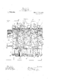
- FIG. l is a longitudinal vertical section of the generator.
- Fig. 2 is a transverse section taken on the line 2-2 of Fig. 1.
- Fig. 3 is a transverse section taken on the line 3 3 ot ⁇ Fig. l.
- Fig. 4f is a detailed view showing one of the dielectric plates forming a part of the generator.
- the numeral l designates a base ot any suitable kind on which the generator is mounted
- the generator comprises a plurality of ring-shaped electrodes 2, 8, 4, 5 and 6, spaced apart and in line with one another.
- the electrodes 2, 4 and 6 are provided with radial extensions 7 (see Fig. 3) which extensions are attached to the elongated strips 8, three in number, and the elecheld in fixed 'relation by these strips.
- the 'electrodes 3 and 5 are held in position by the insulators 10 which are attached at their inner ends to the lugs?) on the electrodes and at their outer ends tothe elongated strips S.
- the electrodes are all spaced from one another so as to leave air aps 11 between them and a r1ngshaped dielectric plate l2 of glass 0r other suitable material is' located in each of the air gaps.
- the electrodes 3 and 5 are connected by means of the' binding post 13 with one side ot a source ot electric current or a suitable voltage for use with Aa machine ot this kind invention relates to ozone generators will pass through tween the adjacent edges ot the e and the electrodes 2, 4 and G are connected, as shown, to the other side off' the same supply.
- Thedischarge takes place through the dielectric plates between the oppositely 'disposed edges 14 of the ring-shaped electrodes in order thatV the ozone-.may he properly diluted or mined with the air which it is intended to-p'urity, each'o the electrodes isprovided with air openings, l5
- the dielectric plates each have ⁇ open centers 16 and the electrode 2 is provided with' a large opening 17.disposed opposite the small opening 18 in the electrode 6.
- the 'operation of the generator is as :tollows: A suitable fan or blower yis arranged to drawl air through the opening 17. This causes air 'from the outside to enter the generat-or through the air gaps lso that it the electric discharges belectrodes and be ozonized; Additional air enters through the openings 15 and the small opening 18 and-mixes with the zonized 'air and is purified.
- the mixture is thus made suiicient-ly dilute for use in living compartments vWhere a high concentration would be objectionable.
- I have indicated the iiow of air through the device by means'o arrows.
- the generator because ot' the high voltage employed, is preferably incased in a suitable insulating or 'grounded case so as to prevent acci ental contact therewith.
- the dielectric. plates are the only parts ot a machine of' this hind which are liable to be damaged and, should this happen, these plates can easily be removedl by removing one of the strips 8, which permits the damaged dielectric plates to he ⁇ lifted out ot the generatorl and new plates inserted.
- a device of the kind described 'a plurality of hollow electrodes having perforation in their: walls and spaced from onefv fixed relation by strips extending alongand secured to their outer walls, substantially as described.
- a plurality of ring-shaped electrodes spaced apart and in line with one another and held in fixed relation by strips extending ⁇ along and secured to their outer walls, and die/led tric ring-shaped plates interposed between said rings, substantially as described.
- a device of the kind described a plurality et ring-shaped electrodes spaced apart and in line with one another and held in fixed relation by strips extendingl along and secured te their cuter walls, and dielectric rings-halved plates interposed between said rings, said electrodes having air clienings adjacent their edges, substantially as described.
Landscapes
- Chemical & Material Sciences (AREA)
- Organic Chemistry (AREA)
- Inorganic Chemistry (AREA)
- Oxygen, Ozone, And Oxides In General (AREA)
Description
W. 0. FREI-ITI OZONE GENERATOR,
APPLICATION FILED JAN, 2s, 1912` LUySm, Eatened July 8, 1913.
2 SHBETS-SHEET l.
ooooow@ W. 0. FREET.
OZONE GENERATOR. PPLGATIoN FILED mums, 1912.
atented July 8, 1913.
2 SHEETS-SHEET 2.
firmatari o. raser,
OF HACKENSACK, NEW JERSEY, ASSIGNOR TG STEYNS'OZN,
COMEANY, A COBPORATIUON OF NEW'YGRK.
OZONE-GENERATOR:
Specicatonof Letters a'tent.
Patented ulg! f application inea January ze, 19m. serial no. svasvo.
o A :fvwm t may concern `known that l, VVInLiAivi O. Fnsn'r, a
citizenoitV the United States, residing 1n.
Hackensack, county of Bergen, and'St-ate of New Jersey, haveinventerd or discovered certain new or useful Improvements in Ozone-Generators, of which the following is a full, clear, and complete disclosure.
Mv ot' a kind suitable for use in producing ozone in small quantities and of relatively low con centration torV purifying the air of apartments and for other uses where only low concentration and limited quantities are desired.
The object of my invention is to provide a compact, durable, reliable device for such use which can be cheaply manufactured and the parts of which can easily be assembled and removed for repairs should they become damaged.
l trodes are In the drawing accompanying and forming a part ot" this speciication, l have illustrated one embodiment of my invention.
In this drawing Figure l is a longitudinal vertical section of the generator. Fig. 2 is a transverse section taken on the line 2-2 of Fig. 1. Fig. 3 is a transverse section taken on the line 3 3 ot `Fig. l. Fig. 4f is a detailed view showing one of the dielectric plates forming a part of the generator.
Referring in detail to the generator shown in these views, the numeral l designates a base ot any suitable kind on which the generator is mounted The generator comprises a plurality of ring-shaped electrodes 2, 8, 4, 5 and 6, spaced apart and in line with one another. The electrodes 2, 4 and 6 are provided with radial extensions 7 (see Fig. 3) which extensions are attached to the elongated strips 8, three in number, and the elecheld in fixed 'relation by these strips. The 'electrodes 3 and 5 are held in position by the insulators 10 which are attached at their inner ends to the lugs?) on the electrodes and at their outer ends tothe elongated strips S. The electrodes are all spaced from one another so as to leave air aps 11 between them and a r1ngshaped dielectric plate l2 of glass 0r other suitable material is' located in each of the air gaps. The electrodes 3 and 5 are connected by means of the' binding post 13 with one side ot a source ot electric current or a suitable voltage for use with Aa machine ot this kind invention relates to ozone generators will pass through tween the adjacent edges ot the e and the electrodes 2, 4 and G are connected, as shown, to the other side off' the same supply. Thedischarge takes place through the dielectric plates between the oppositely 'disposed edges 14 of the ring-shaped electrodes in order thatV the ozone-.may he properly diluted or mined with the air which it is intended to-p'urity, each'o the electrodes isprovided with air openings, l5
located adiacent the edges of the electrode and distributed around the .circular wall of the elect-rode so that air may enter through these openings and mingle with vthe ozonized air. The dielectric plates each have` open centers 16 and the electrode 2 is provided with' a large opening 17.disposed opposite the small opening 18 in the electrode 6. The 'operation of the generator is as :tollows: A suitable fan or blower yis arranged to drawl air through the opening 17. This causes air 'from the outside to enter the generat-or through the air gaps lso that it the electric discharges belectrodes and be ozonized; Additional air enters through the openings 15 and the small opening 18 and-mixes with the zonized 'air and is purified. The mixture is thus made suiicient-ly dilute for use in living compartments vWhere a high concentration would be objectionable. I have indicated the iiow of air through the device by means'o arrows. While l have not shown the saine, it is to be understood that the generator, because ot' the high voltage employed, is preferably incased in a suitable insulating or 'grounded case so as to prevent acci ental contact therewith. The dielectric. plates are the only parts ot a machine of' this hind which are liable to be damaged and, should this happen, these plates can easily be removedl by removing one of the strips 8, which permits the damaged dielectric plates to he` lifted out ot the generatorl and new plates inserted.
Having now described 'my invention and mode of its use` what l claim is: l
l. Tn a device of the kind described, 'a plurality of hollow electrodes having perforation in their: walls and spaced from onefv fixed relation by strips extending alongand secured to their outer walls, substantially as described.
l 3. In a device of the kind described, a plurality of ring-shaped electrodes spaced apart and in line with one another and held in fixed relation by strips extending` along and secured to their outer walls, and die/led tric ring-shaped plates interposed between said rings, substantially as described.
4:. ln a. device et the kind described, a plurality 'of parallel strips, a plurality ef ring-shaped electrodes attached directly to said strips7 and a plurality of ring-shaped electrodes interposed between and alternating with said first named electrodes and secured te said strips indirectly by means ci insulators, substantially a described.
5. ln a device of the kind described, a plurality et ring-shaped electrodes spaced apart and in line with one another and held in fixed relation by strips extendingl along and secured te their cuter walls, and dielectric rings-halved plates interposed between said rings, said electrodes having air clienings adjacent their edges, substantially as described.
wWILLl'rrill G. Fltiflll'l.
Witnesses:
James J. Cesencvn, lli. M. ltmlic'ies.
Priority Applications (1)
| Application Number | Priority Date | Filing Date | Title |
|---|---|---|---|
| US67287012A US1066484A (en) | 1912-01-23 | 1912-01-23 | Ozone-generator. |
Applications Claiming Priority (1)
| Application Number | Priority Date | Filing Date | Title |
|---|---|---|---|
| US67287012A US1066484A (en) | 1912-01-23 | 1912-01-23 | Ozone-generator. |
Publications (1)
| Publication Number | Publication Date |
|---|---|
| US1066484A true US1066484A (en) | 1913-07-08 |
Family
ID=3134727
Family Applications (1)
| Application Number | Title | Priority Date | Filing Date |
|---|---|---|---|
| US67287012A Expired - Lifetime US1066484A (en) | 1912-01-23 | 1912-01-23 | Ozone-generator. |
Country Status (1)
| Country | Link |
|---|---|
| US (1) | US1066484A (en) |
Cited By (1)
| Publication number | Priority date | Publication date | Assignee | Title |
|---|---|---|---|---|
| US4603031A (en) * | 1985-05-28 | 1986-07-29 | Gelbman Howard A | Ozone generator |
-
1912
- 1912-01-23 US US67287012A patent/US1066484A/en not_active Expired - Lifetime
Cited By (1)
| Publication number | Priority date | Publication date | Assignee | Title |
|---|---|---|---|---|
| US4603031A (en) * | 1985-05-28 | 1986-07-29 | Gelbman Howard A | Ozone generator |
Similar Documents
| Publication | Publication Date | Title |
|---|---|---|
| US788557A (en) | Electrical ozonizer. | |
| US4214995A (en) | Ozone generator | |
| US1066484A (en) | Ozone-generator. | |
| US1588976A (en) | Electrical apparatus for generating ozone | |
| US935457A (en) | Apparatus for electrically treating air and other gases. | |
| US1157859A (en) | Ozone-generator. | |
| US1010777A (en) | Ozonizer. | |
| US807964A (en) | Apparatus for producing ozone. | |
| US919445A (en) | Ozonizer. | |
| US1803600A (en) | Apparatus for making ozone | |
| US804291A (en) | Albert o | |
| US1912053A (en) | Electrical precipitator | |
| US950347A (en) | Ozone-generator. | |
| US977336A (en) | Means for filtering air and producing ozone. | |
| GB854616A (en) | Apparatus for producing ozone | |
| US1082529A (en) | Apparatus for forming oxids of nitrogen. | |
| US1044700A (en) | Ozonizer. | |
| US1066674A (en) | Apparatus and method for the production of ozone. | |
| US1179927A (en) | Device for producing oxids of nitrogen. | |
| US324010A (en) | Elegtric generator or spark-producing apparatus | |
| US1063167A (en) | Ozone-producing machine. | |
| SU426448A1 (en) | PLASTIC OZONATOR | |
| US717006A (en) | Transformer. | |
| US779810A (en) | Electric branding apparatus. | |
| US530727A (en) | Rheostat |