US1066211A - By-pass valve for locomotive-engines. - Google Patents
By-pass valve for locomotive-engines. Download PDFInfo
- Publication number
- US1066211A US1066211A US76039413A US1913760394A US1066211A US 1066211 A US1066211 A US 1066211A US 76039413 A US76039413 A US 76039413A US 1913760394 A US1913760394 A US 1913760394A US 1066211 A US1066211 A US 1066211A
- Authority
- US
- United States
- Prior art keywords
- valves
- valve chest
- locomotive
- ports
- chest
- Prior art date
- Legal status (The legal status is an assumption and is not a legal conclusion. Google has not performed a legal analysis and makes no representation as to the accuracy of the status listed.)
- Expired - Lifetime
Links
Images

Classifications
-
- F—MECHANICAL ENGINEERING; LIGHTING; HEATING; WEAPONS; BLASTING
- F01—MACHINES OR ENGINES IN GENERAL; ENGINE PLANTS IN GENERAL; STEAM ENGINES
- F01B—MACHINES OR ENGINES, IN GENERAL OR OF POSITIVE-DISPLACEMENT TYPE, e.g. STEAM ENGINES
- F01B25/00—Regulating, controlling or safety means
-
- F—MECHANICAL ENGINEERING; LIGHTING; HEATING; WEAPONS; BLASTING
- F01—MACHINES OR ENGINES IN GENERAL; ENGINE PLANTS IN GENERAL; STEAM ENGINES
- F01B—MACHINES OR ENGINES, IN GENERAL OR OF POSITIVE-DISPLACEMENT TYPE, e.g. STEAM ENGINES
- F01B2250/00—Accessories of steam engines; Arrangements or control devices of pumps, compressors or condensers, insofar as they influence the functioning of the steam engines
- F01B2250/004—Devices for draining or idling of steam cylinders or for uncoupling piston and connecting rod
Definitions
- My present invention isan' improvement upon that for. which Letters-Patent of the United States No.” issued to me undert-date of August 3', 1897 j and its object is to a' nsure the practical and the appliance unl der higher steam pressures than those for ,isatisfactory operation of which it "was originally designed.
- a'valve chest or casing 1, which is connected to the cylinder, 2, of a locomotive engine, through lateral tubular branches or nozzles, 1*,- each of which communicates with one of the steam induction and 'eduction passages, 2, of the cylinder, ball joint rings, 1, being interposed to insure properly steam tight joints.
- the valve chest, 1, is closed at each end,-by a removable head, 1, secured to the chest by studs, 1, said headsfitting in the ends of the chest and being bored out at their inner ends to form plunger chambers, 1 of smaller diameter thanthe interior of the chest.
- Annular steam chambers, 1 are formed around the plunger chambers, by peripheral grooves in theheads.
- valves which are in the form of-hollow pistons, closed at 'tl'ieir outer ends, and provided'with peripheral packing rings, 3, said pistons beingadapted to close on annular seats,;l in the,
- bypass valves 3,.said plun, ;ers being fitted Wlllh packlng rings, 3!.
- valves may,
- a floating piston, 5 is fitted in the tub'u; lar body of each'of the valves, 3, said pisdista'nce apartthat whenthe valves are seated, ,each piston will closely adjoin the tion of the valve chest, and pipes, 1, leadpipe, 4', leads from the adjacent valve chest air admission port,-
- betweern-the' cylim the vala'e'sfthe a nnulajr 1 m mbers l the plungrsg' 3fl aiidthe wall of the valve chest perform the function of dash,- pots'for cushioning the valves in theirj unseatinginove- 'I nents,, by .causingthe outer ends of the bodies of the valves to come-to rest, without shock, against the inner ends of the heads,
- valves in the closing or seating movements of the ingwith the induction and edufction ports' thereof, two byo-pass' val'ves,'eac h seating in said valve chest and controlling commumcation between the same'and' one of said ports, said valves" being-nOrmaIIy subject to.
- valve chest pressure means forlunseati ng-"said valves upon the relief of suchpiess'ure', and dash pot means said valves being normally subject to an for cushioning jsaid 'va'lves in their unseating movements.
- gine cylinder of a valve chest communicat ing with the. induction and eduction ports thereof, heads, each detachably connected to aud closing one end of said valve chest and having.” an inwardly projecting plunger chamber, two by-pass valves, each seating in said valve chest, and controlhng communication between the same" and one of sald ports,- said valves being normally subject to and closed by distributionvalve chest pres-.
- valve chest communicatmg with the induction and eduction ports thereof, two tubular "by-pass valves, each vseat-ing'in said valve chest, and controlling communication between the same and one. ,of said. ports, said valves being normally subject to and closed by distribution valve chest pressure, means for unseating said valves upon the relief of such pressure, dash pot means for cushioning said valves in their unseatmg movements, and connected float-' mg plstons, each fitting in one, of the tubular by-pass valves.
Landscapes
- Engineering & Computer Science (AREA)
- Mechanical Engineering (AREA)
- General Engineering & Computer Science (AREA)
- Lift Valve (AREA)
Description
0. J. MELLIN. BY-PASS VALVE FOR LOOOMOTIVE ENGINES.
APPLICATION FILED APR.11, 1913-. I v
Patented July 1, 1913.
2 SHEETS-SHEET 1.
unirhDS'rArns PATENT enrich CARL J) mmjnm ,=es 'scnnnnc'rnnv, new YORK.
7 express. vnav'n m; riooomorrvn-nnsrnns.
To all whom it may concern Be it known that-1,0ARL J. MELLI of.
Schenectady, in the county of Schenectady and State of New York, have invented a- 5 certain new and useful Improvement in-By Pass Valves for Locomotive-Engines, of which improvement the followingjis a speci: fication. W
My present invention isan' improvement upon that for. which Letters-Patent of the United States No." issued to me undert-date of August 3', 1897 j and its object is to a' nsure the practical and the appliance unl der higher steam pressures than those for ,isatisfactory operation of which it "was originally designed.
The improvement claimed is hereinafter fully se't forth. j
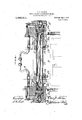
y In the-accompanying drawings: Figure 1 tion through the same, on the line a a of Fig. 1; and, Fig. 3, a section taken similarly to Fig. 1, illustrating a structural 1 modification,
Referringfirst to Figs. 1 and 2,, in the .practicebf my invention I provide a'valve chest or casing, 1, which is connected to the cylinder, 2, of a locomotive engine, through lateral tubular branches or nozzles, 1*,- each of which communicates with one of the steam induction and 'eduction passages, 2, of the cylinder, ball joint rings, 1, being interposed to insure properly steam tight joints. The valve chest, 1, is closed at each end,-by a removable head, 1, secured to the chest by studs, 1, said headsfitting in the ends of the chest and being bored out at their inner ends to form plunger chambers, 1 of smaller diameter thanthe interior of the chest. Annular steam chambers, 1 are formed around the plunger chambers, by peripheral grooves in theheads.
Communication between the interior of the valve chest and the cylinder ports, 2, 1s
controlled by two by-pass valves, 3, 3, which are in the form of-hollow pistons, closed at 'tl'ieir outer ends, and provided'with peripheral packing rings, 3, said pistons beingadapted to close on annular seats,;l in the,
' casing, which seats are located on the inner sides of the passages through the tubular branches, 1.' 'Aplu'nger, 3, fitting truly 15 in. the plunger chamber-of the ad acent head,- --isformed upon thefouter end of each of the Specification of'Lette rs Patent, Application filed April 11, 1913. Serial No. 76(1394,
- said chambers. A small $87,505 weregranted and" 'is aa vertical longitudinal central section through a by-pass valve appliance embody mg 'my invention; Fig. 2, a transverse sec- Patented Ju1y1,1913.
bypass valves, 3,.said plun, ;ers being fitted Wlllh packlng rings, 3!. A steam supply or steam supply, passage of tl1'e locomotive, into each of the steam supply chambers, 1, and communicates with the plunger chambers,l", through ports, 1', in the walls of 1 which may, if desired, be piped toany ipreferred-location of admission of atmospheric air, is formed in the Wall of the valve .phest, intermediate of the valves, '3, said iportadmitting airat atmospheric pressure, to efiect'the unseat-mg of the by'-pass "valves,
the closure-of the throttle. valves may,
interposedsprmg', as shown-in Letters Patout No 587,505 aforesaid. I j A floating piston, 5, is fitted in the tub'u; lar body of each'of the valves, 3, said pisdista'nce apartthat whenthe valves are seated, ,each piston will closely adjoin the tion of the valve chest, and pipes, 1, leadpipe, 4', leads from the adjacent valve chest air admission port,-
vwhen the supply of steam to the engine cyl- E inder's and distribution'valves is cut cit by The bypass if .preferred, be unseatcd-by an tons being connected by a rod, 5 at such a I ing to the exterior of the c linder casting,
are connected to said ports.
In the operation of the appliance, when the locomotive is running with the throttle valve open, steam from the valve chest is supplied to the plunger chambers,l through the pipes, at, and ports, 1 and acting on the plungers, 3 forces the by-pass valves, 3, to their seats, and cuts ofi communication,
of the pistons,'releases pressure from the atmospheric pressure, entering the valve through the valve chest, between the cylin: der ports, 2?. :When. the engine is drifting, or runnin'gvwith throttle closed, the vacuum produced in the cylinders by the movements outer ends of the plungjers, 3}, and; air at' U chest through the port, ,1,- unse'ats; the
valves, 3, and;.permitsfree circulation ofair, l
der ports,-2. In't h openingfznogteznents ojl t.
through the valve chest, betweern-the' cylim the vala'e'sfthe a nnulajr 1 m mbers l the plungrsg' 3fl aiidthe wall of the valve chest perform the function of dash,- pots'for cushioning the valves in theirj unseatinginove- 'I nents,, by .causingthe outer ends of the bodies of the valves to come-to rest, without shock, against the inner ends of the heads,
1. A similarcushioning result is. effected,
" in the closing or seating movements of the ingwith the induction and edufction ports' thereof, two byo-pass' val'ves,'eac h seating in said valve chest and controlling commumcation between the same'and' one of said ports, said valves" being-nOrmaIIy subject to. and
clcsed by distribution valve chest pressure, means forlunseati ng-"said valves upon the relief of suchpiess'ure', and dash pot means said valves being normally subject to an for cushioning jsaid 'va'lves in their unseating movements.
2.; The combination, with: a locomotive engine cylinder, of a valve chest communicating with the induction and edu'ction ports thereof, two by-pass valves, each'seating in said valve 'chest and controlling 'conimunica-s tion between the-same and one of said ports' closed by distribution valve chest pressure,
' means for unseating said valves upon the relief of such pressure, dash -pot means for cushioning said valves in their unseating' -1novements, and means, located on the opposite sides of said valves, i fo-r cushlonmg them in their seating movem'en'ts.
3. The comblnation, with a locomotive en,-
gine cylinder, of a valve chest communicat ing with the. induction and eduction ports thereof, heads, each detachably connected to aud closing one end of said valve chest and having." an inwardly projecting plunger chamber, two by-pass valves, each seating in said valve chest, and controlhng communication between the same" and one of sald ports,- said valves being normally subject to and closed by distributionvalve chest pres-. sure, means forunseating said valves upon municating' with, the induction andeduction ports thereof, heads, each detachablyifcom nected to and closing'one end of said valve chest, and having .an inwardly projecting plungerchamber surrounded by an annularstea-m chamber, a'pipe fornormallyestab lishing communication between said steam chambers and a distribution valve chest of the locomotive, two by-pass valves, each seating 1n the' by-pass .valve chest and controlling communication between the same-and one of, the cylinder ports, means for unseat-. ,ing said valves upon the relief of pressure in thesteam'chambers, and plungers fixed on-said valves and fitting the plunger chamber.
, 5L The combination, with a locomotive engine cylinder, of a valve chest communicatmg with the induction and eduction ports thereof, two tubular "by-pass valves, each vseat-ing'in said valve chest, and controlling communication between the same and one. ,of said. ports, said valves being normally subject to and closed by distribution valve chest pressure, means for unseating said valves upon the relief of such pressure, dash pot means for cushioning said valves in their unseatmg movements, and connected float-' mg plstons, each fitting in one, of the tubular by-pass valves.
. CARL J. MELLIN. Witnesses:
-ROBERT F. HALL, E. I. SCIIAUBER.
Copies of this-patent may be obtained for five cents each, by addressing the Commissioner of Patents.
WaShington D. C.
Priority Applications (1)
| Application Number | Priority Date | Filing Date | Title |
|---|---|---|---|
| US76039413A US1066211A (en) | 1913-04-11 | 1913-04-11 | By-pass valve for locomotive-engines. |
Applications Claiming Priority (1)
| Application Number | Priority Date | Filing Date | Title |
|---|---|---|---|
| US76039413A US1066211A (en) | 1913-04-11 | 1913-04-11 | By-pass valve for locomotive-engines. |
Publications (1)
| Publication Number | Publication Date |
|---|---|
| US1066211A true US1066211A (en) | 1913-07-01 |
Family
ID=3134454
Family Applications (1)
| Application Number | Title | Priority Date | Filing Date |
|---|---|---|---|
| US76039413A Expired - Lifetime US1066211A (en) | 1913-04-11 | 1913-04-11 | By-pass valve for locomotive-engines. |
Country Status (1)
| Country | Link |
|---|---|
| US (1) | US1066211A (en) |
-
1913
- 1913-04-11 US US76039413A patent/US1066211A/en not_active Expired - Lifetime
Similar Documents
| Publication | Publication Date | Title |
|---|---|---|
| US773365A (en) | Fluid-pressure motor. | |
| USRE24532E (en) | Cushioning structure for hydraulic cylinders | |
| US1147436A (en) | Hydropneumatic locomotive reversing-gear. | |
| US802104A (en) | Water-motor. | |
| US298063A (en) | bogert | |
| US448001A (en) | bated | |
| US797496A (en) | Valve for compound locomotives. | |
| US233436A (en) | Self and eobeet faeley | |
| US741838A (en) | Compound steam-engine. | |
| US1175087A (en) | Intercepting-valve for compound engines. | |
| US400374A (en) | Valve for locomotives | |
| US936773A (en) | Steam-engine valve. | |
| US412226A (en) | Abraham l | |
| US170938A (en) | Improvement in steam pumping-engines | |
| US199961A (en) | Improvement in steam-engines | |
| US679949A (en) | Steam-engine. | |
| US1095931A (en) | Locomotive drifting-valve. | |
| GB190513930A (en) | Improvements in Apparatus for Operating Steering Engines and like Gear from a Distance. | |
| US1106338A (en) | Steam-engine. | |
| US1068937A (en) | Cylinder for steam-engines and the like. | |
| US502462A (en) | jellingeaus | |
| US1041697A (en) | Valve. | |
| US1271938A (en) | Steam-valve. | |
| US1033930A (en) | Steam-engine. | |
| US848079A (en) | Steam-cylinder drain-valve. |