US10658675B1 - Freeze tape cast metallic current collectors - Google Patents
Freeze tape cast metallic current collectors Download PDFInfo
- Publication number
- US10658675B1 US10658675B1 US16/178,321 US201816178321A US10658675B1 US 10658675 B1 US10658675 B1 US 10658675B1 US 201816178321 A US201816178321 A US 201816178321A US 10658675 B1 US10658675 B1 US 10658675B1
- Authority
- US
- United States
- Prior art keywords
- struts
- electrode
- active material
- metal
- void spaces
- Prior art date
- Legal status (The legal status is an assumption and is not a legal conclusion. Google has not performed a legal analysis and makes no representation as to the accuracy of the status listed.)
- Expired - Fee Related
Links
Images


Classifications
-
- H—ELECTRICITY
- H01—ELECTRIC ELEMENTS
- H01M—PROCESSES OR MEANS, e.g. BATTERIES, FOR THE DIRECT CONVERSION OF CHEMICAL ENERGY INTO ELECTRICAL ENERGY
- H01M4/00—Electrodes
- H01M4/02—Electrodes composed of, or comprising, active material
- H01M4/64—Carriers or collectors
- H01M4/70—Carriers or collectors characterised by shape or form
- H01M4/72—Grids
- H01M4/74—Meshes or woven material; Expanded metal
-
- H—ELECTRICITY
- H01—ELECTRIC ELEMENTS
- H01M—PROCESSES OR MEANS, e.g. BATTERIES, FOR THE DIRECT CONVERSION OF CHEMICAL ENERGY INTO ELECTRICAL ENERGY
- H01M10/00—Secondary cells; Manufacture thereof
- H01M10/05—Accumulators with non-aqueous electrolyte
- H01M10/052—Li-accumulators
-
- H—ELECTRICITY
- H01—ELECTRIC ELEMENTS
- H01M—PROCESSES OR MEANS, e.g. BATTERIES, FOR THE DIRECT CONVERSION OF CHEMICAL ENERGY INTO ELECTRICAL ENERGY
- H01M4/00—Electrodes
- H01M4/02—Electrodes composed of, or comprising, active material
- H01M4/64—Carriers or collectors
- H01M4/66—Selection of materials
- H01M4/661—Metal or alloys, e.g. alloy coatings
-
- H—ELECTRICITY
- H01—ELECTRIC ELEMENTS
- H01M—PROCESSES OR MEANS, e.g. BATTERIES, FOR THE DIRECT CONVERSION OF CHEMICAL ENERGY INTO ELECTRICAL ENERGY
- H01M4/00—Electrodes
- H01M4/02—Electrodes composed of, or comprising, active material
- H01M4/64—Carriers or collectors
- H01M4/70—Carriers or collectors characterised by shape or form
- H01M4/72—Grids
- H01M4/74—Meshes or woven material; Expanded metal
- H01M4/742—Meshes or woven material; Expanded metal perforated material
-
- H—ELECTRICITY
- H01—ELECTRIC ELEMENTS
- H01M—PROCESSES OR MEANS, e.g. BATTERIES, FOR THE DIRECT CONVERSION OF CHEMICAL ENERGY INTO ELECTRICAL ENERGY
- H01M4/00—Electrodes
- H01M4/02—Electrodes composed of, or comprising, active material
- H01M4/64—Carriers or collectors
- H01M4/70—Carriers or collectors characterised by shape or form
- H01M4/75—Wires, rods or strips
-
- H—ELECTRICITY
- H01—ELECTRIC ELEMENTS
- H01M—PROCESSES OR MEANS, e.g. BATTERIES, FOR THE DIRECT CONVERSION OF CHEMICAL ENERGY INTO ELECTRICAL ENERGY
- H01M4/00—Electrodes
- H01M4/02—Electrodes composed of, or comprising, active material
- H01M4/64—Carriers or collectors
- H01M4/70—Carriers or collectors characterised by shape or form
- H01M4/78—Shapes other than plane or cylindrical, e.g. helical
-
- H—ELECTRICITY
- H01—ELECTRIC ELEMENTS
- H01M—PROCESSES OR MEANS, e.g. BATTERIES, FOR THE DIRECT CONVERSION OF CHEMICAL ENERGY INTO ELECTRICAL ENERGY
- H01M4/00—Electrodes
- H01M4/86—Inert electrodes with catalytic activity, e.g. for fuel cells
- H01M4/88—Processes of manufacture
- H01M4/8825—Methods for deposition of the catalytic active composition
- H01M4/8857—Casting, e.g. tape casting, vacuum slip casting
-
- Y—GENERAL TAGGING OF NEW TECHNOLOGICAL DEVELOPMENTS; GENERAL TAGGING OF CROSS-SECTIONAL TECHNOLOGIES SPANNING OVER SEVERAL SECTIONS OF THE IPC; TECHNICAL SUBJECTS COVERED BY FORMER USPC CROSS-REFERENCE ART COLLECTIONS [XRACs] AND DIGESTS
- Y02—TECHNOLOGIES OR APPLICATIONS FOR MITIGATION OR ADAPTATION AGAINST CLIMATE CHANGE
- Y02E—REDUCTION OF GREENHOUSE GAS [GHG] EMISSIONS, RELATED TO ENERGY GENERATION, TRANSMISSION OR DISTRIBUTION
- Y02E60/00—Enabling technologies; Technologies with a potential or indirect contribution to GHG emissions mitigation
- Y02E60/10—Energy storage using batteries
-
- Y—GENERAL TAGGING OF NEW TECHNOLOGICAL DEVELOPMENTS; GENERAL TAGGING OF CROSS-SECTIONAL TECHNOLOGIES SPANNING OVER SEVERAL SECTIONS OF THE IPC; TECHNICAL SUBJECTS COVERED BY FORMER USPC CROSS-REFERENCE ART COLLECTIONS [XRACs] AND DIGESTS
- Y02—TECHNOLOGIES OR APPLICATIONS FOR MITIGATION OR ADAPTATION AGAINST CLIMATE CHANGE
- Y02E—REDUCTION OF GREENHOUSE GAS [GHG] EMISSIONS, RELATED TO ENERGY GENERATION, TRANSMISSION OR DISTRIBUTION
- Y02E60/00—Enabling technologies; Technologies with a potential or indirect contribution to GHG emissions mitigation
- Y02E60/30—Hydrogen technology
- Y02E60/50—Fuel cells
Definitions
- This disclosure relates to freeze tape cast metallic current collectors for electrochemical devices.
- Three-dimensional metallic current collectors such as metal foams, for electrochemical devices provide mechanically robust and high-capacity electrodes. These electrodes also have an established, ordered conductive percolated network within the electrode structure-decreasing electron travel distance through electrochemically active material. Due to the percolated conductive network and mechanical robustness of three-dimensional metallic current collectors, thicker and higher capacity electrodes can be utilized when compared to traditional metallic foil or expanded metal current collectors. While metallic foam allows for thick and high capacity electrodes, the randomized nature of the thin metallic strands and pore structure limits the electronic conductivity and active material utilization of the electrodes especially at high rates of discharge.
- An electrode includes a current collector having metallic struts, formed by freeze tape casting along a cast direction, that define a percolated conductive network and void spaces through the percolated conductive network, and an electrochemically active material occupying portions of the void spaces.
- the struts are directionally aligned and the void spaces are directionally ordered perpendicular to the cast direction.
- a battery has an electrode including a current collector having freeze tape cast metallic struts that define a percolated conductive network and void spaces through the percolated conductive network, and an electrochemically active material occupying portions of the void spaces.
- the struts are directionally aligned and the void spaces are directionally ordered perpendicular to a cast direction of the struts.
- An electrode includes a current collector having active material metallic struts, formed by freeze tape casting along a cast direction, that define a percolated conductive network and void spaces through the percolated conductive network.
- the struts are directionally aligned and the void spaces are directionally ordered perpendicular to the cast direction.
- FIG. 1 is a side view, in cross-section, of an electrode containing an active material impregnating a single-sided freeze tape cast metallic current collector wherein the metallic struts each taper from one end to another.
- FIG. 2 is a side view, in cross-section, of an electrode containing an active material impregnating a dual sided freeze tape cast metallic current collector wherein the metallic struts each taper from opposite ends toward a middle thereof.
- FIG. 3 is top view of an electrode containing an active material impregnating a freeze tape cast metallic current collector wherein the metallic struts are parallel to each other.
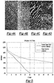
- FIGS. 4A-4D are cross-sections of microstructure cut at 90°, 50°, 40° and 0° respectively relative to the cast direction.
- FIG. 5 is a plot comparing utilization versus C-rate for half-cells with either metallic foam or freeze tape cast metallic current collectors.
- Freeze-casting is a solidification technique for fabricating porous materials. During solidification, walls are templated due to rejection of particles and/or solute by a solidifying fluid. Pore structures created after post-solidification solid removal replicate the morphology of the solidified fluid.
- the number and diversity of potential freeze casting applications is considerable and include substrates for supercapacitors, photocatalysis, liquid chromatography, sensors (e.g. pressure, biological and gas), and batteries. Thus far, ceramic/metal, ceramic/polymer, metal/polymer, and metal/metal composites have been demonstrated.
- the freeze tape casting process is like the freeze casting process as a suspension is drawn onto a freeze bed, where the solvent (water) begins to solidify and ice crystals nucleate between the suspension and freeze bed. The ice grows upwards and displaces other particles within the suspension. The ice is sublimed from the cast tape by lyophilization and results in a scaffold containing porosity that matches the size and shape of the ice crystals.
- Freeze tape casting diverges from the traditional freeze casting method in that the suspension is drawn through a doctor blade, which determines the height of the cast, and by matching the speed of the ice crystal growth with that of the tape carrier speed, a uniform solidification front can be achieved. This results in directionally aligned metallic struts spanning the width of the cast. Unlike traditional freeze casting in which freeze cast domains and grain boundaries in the bulk cast material limit pore ordering to several hundred microns, the freeze tape casting process forms a single freeze cast domain that extends to the macro scale. This ordered freeze cast domain permits bulk materials to be fabricated with intrinsic anisotropy structures specifically tailored for desired applications.
- Powder metallurgy-based freeze tape casting presents a unique opportunity to engineer pore structures in metals for catalyst support and energy conversion devices. While traditional freeze casting has been employed with titanium, the process of freezing in dies and molds limits pore ordering to several hundred microns due to the formation of freeze cast domains which is synonymous with grain boundaries on a macro scale.
- freeze-cast microstructures are most commonly described in terms of total porosity, structure wavelength, and pore and wall sizes.
- Structure wavelength is defined as the average sum of the width of one pore plus its adjacent wall. This parameter, traditionally used to describe primary dendrite spacing in metal alloys, only applies to anisotropic freeze-cast materials and is most commonly used to describe lamellar structures.
- anisotropic microstructures pore and wall size is typically described in terms of width (the length of the minor axis), whereas for isotropic structures, diameter is used.
- Metallic current collectors fabricated with the freeze tape casting method produce directionally aligned metallic struts that define a percolated conductive network and ordered void spaces through the percolated conductive network.
- the freeze tape cast metallic current collector provides the same benefits of a three-dimensional metallic foam; however, the structure does not have the drawbacks of electronic tortuosity associated with the randomized thin metallic strands and void spaces in metal foams.
- the aligned metallic struts of the freeze tape cast current collector reduce electronic tortuosity resulting in a significant increase in conductivity as well as creating a more uniform distribution of active material, which promotes more efficient utilization of the electrode structure. This design enables electrodes to be capable of high power and capacity not before achievable with existing random foam type metallic electrodes.
- FIG. 1 is a side view of an electrode 10 , according to the present disclosure, including an active material 12 impregnating a single sided freeze tape cast metallic current collector 14 defining directionally aligned metallic struts 16 that each taper from one end to another.
- FIG. 2 is a side view of an electrode 110 , according to the present disclosure, including an active material 112 impregnating a dual sided freeze tape cast metallic current collector 114 defining directionally aligned metallic struts 116 that each taper from opposite ends toward a middle thereof.
- FIG. 3 is a top view of an electrode 210 , according to the present disclosure, including an active material 212 impregnating a freeze tape cast metallic current collector 214 defining metallic struts 216 .
- the struts may be plated with, for example, a metallic element. Also, the struts may be aluminum, copper, gold, iron, lead, nickel, silver, stainless steel, titanium, or zinc.
- the active material may form an anode, cathode, or catalyst. If the active material forms an anode, it may be metals, metal hydroxides, metal hydrides, metal oxides or combinations thereof. Examples of anode active materials include aluminum, cadmium, iron, lead, lithium, lithium titanate, magnesium, sodium, zinc, or zinc oxide. If the active material forms a cathode, it may be catalyzed oxygen, metal oxides, metal hydroxides, metal phosphates, or sulfur complexes.
- cathode active materials include iron sulfur, lead dioxide, lithium cobalt oxide, lithium iron phosphate, lithium manganese oxide, lithium nickel manganese cobalt oxide, lithium nickel cobalt aluminum oxide, manganese dioxide, mercury oxide, nickel hydroxide, silver oxide, or sulfur.
- FIGS. 4A through 4D illustrate the anisotropy of the pores that gives rise to variations observed in physical properties.
- Cross-sections viewed in the direction of casting show a highly ordered pattern of alternating solids and porosity (percolated conductive network and void spaces) arranged in vertical columns propagating throughout the thickness of the sample.
- the images indicate that the pore walls are observed as closely packed columns or “struts,” where the struts are only loosely connected in the direction of casting, but highly interconnected perpendicular to that direction. In this manner, only the thin cross-section of the pore wall, or strut, can be seen at 90° but the surface of the pore wall in addition to small portions of the strut can be observed at 0°.
- the observed skewing from vertical indicated at 40° is due to the bottom of the tape freezing prior to the top of the tape while the tape was in motion, which provides yet another mechanism for tailoring the porosity in terms of pore tilting.
- the areas seen in the cross-sectional image at 0° can be further explained as sections of overlapping struts, hence observation of pore wall surfaces, that are truncated when cross-sectioned as a result of not being entirely vertical when viewed at 0°.
- Half-cell tests were performed with both foam and freeze tape cast metallic current collectors impregnated with a nickel hydroxide active material.
- the half-cells contained a zinc reference and a nickel foam gassing counter electrode and were bathed in an electrolyte consisting primarily of potassium hydroxide and water.
- the half-cells were completely formed and then tested at multiple discharge C-rates, ranging from C/6 to 50 C. After each discharge, the cells were fully charged and given a rest of 15 minutes at open circuit potential between charges and discharges.
- the electrode utilizing the freeze tape cast current collector vastly outperformed the traditional foam electrode.
- the freeze tape cast current collector outperformed the foam electrode at every tested C-rate and had utilization gains of 28.7% at a 10 C rate and 284.5% at a 20 rate.
- the struts 16 , 116 , 216 of the current collectors 14 , 114 , 214 may be formed from active material such as aluminum, cadmium, iron, lead, lithium, nickel, platinum, silver, or zinc. In these arrangements, active material would not fill the gaps between the struts 16 , 116 , 216 . Rather, electrolyte may occupy such space. Other arrangements are also possible.
Landscapes
- Chemical & Material Sciences (AREA)
- Chemical Kinetics & Catalysis (AREA)
- Electrochemistry (AREA)
- General Chemical & Material Sciences (AREA)
- Engineering & Computer Science (AREA)
- Manufacturing & Machinery (AREA)
- Materials Engineering (AREA)
- Cell Electrode Carriers And Collectors (AREA)
Abstract
Description
Claims (18)
Priority Applications (1)
| Application Number | Priority Date | Filing Date | Title |
|---|---|---|---|
| US16/178,321 US10658675B1 (en) | 2018-11-01 | 2018-11-01 | Freeze tape cast metallic current collectors |
Applications Claiming Priority (1)
| Application Number | Priority Date | Filing Date | Title |
|---|---|---|---|
| US16/178,321 US10658675B1 (en) | 2018-11-01 | 2018-11-01 | Freeze tape cast metallic current collectors |
Publications (2)
| Publication Number | Publication Date |
|---|---|
| US20200144625A1 US20200144625A1 (en) | 2020-05-07 |
| US10658675B1 true US10658675B1 (en) | 2020-05-19 |
Family
ID=70458997
Family Applications (1)
| Application Number | Title | Priority Date | Filing Date |
|---|---|---|---|
| US16/178,321 Expired - Fee Related US10658675B1 (en) | 2018-11-01 | 2018-11-01 | Freeze tape cast metallic current collectors |
Country Status (1)
| Country | Link |
|---|---|
| US (1) | US10658675B1 (en) |
Citations (2)
| Publication number | Priority date | Publication date | Assignee | Title |
|---|---|---|---|---|
| US20150072236A1 (en) * | 2013-04-19 | 2015-03-12 | CellMotive Co. Ltd. | Metal Foam for Electrode of Secondary Lithium Battery, Preparing Method Thereof, and Secondary Lithium Battery Including the Metal Foam |
| US20170100857A1 (en) * | 2015-10-13 | 2017-04-13 | The Regents Of The University Of California | Bidirectional freeze casting for fabricating lamellar structures |
-
2018
- 2018-11-01 US US16/178,321 patent/US10658675B1/en not_active Expired - Fee Related
Patent Citations (2)
| Publication number | Priority date | Publication date | Assignee | Title |
|---|---|---|---|---|
| US20150072236A1 (en) * | 2013-04-19 | 2015-03-12 | CellMotive Co. Ltd. | Metal Foam for Electrode of Secondary Lithium Battery, Preparing Method Thereof, and Secondary Lithium Battery Including the Metal Foam |
| US20170100857A1 (en) * | 2015-10-13 | 2017-04-13 | The Regents Of The University Of California | Bidirectional freeze casting for fabricating lamellar structures |
Non-Patent Citations (5)
| Title |
|---|
| Benjamin Delattre et al., "Impact of Pore Tortuosity on Electrode Kinetics in Lithium Battery Electrodes: Study in Directionally Freeze-Cast LiNi0.8Co0.15AI0.05O2 (NCA)", Journal of the Electwchernical Society, 165 (2), 2018, pp. A388-A395. |
| David Driscoll et al., Electrical and Flexural Anisotropy in Freeze Tape Cast Stainless Steel Porous Substrates, ScienceDirect, Materials Letters 65 (2011), pp. 3433-3435. |
| Francisco Garcia-Moreno, Commercial Applications of Metal Foams: Their Properties and Production', MMPI Materials Journal, 2016, pp. 1-27. |
| Kristen L. Scott et al., A Review of Processing, Microstructure and Properties via the Open Data Repository, FreezeCasting.net, Progressive Materials Science (2018), 143 pgs. |
| Milad Azami Ghadkolai et al., "Freeze Tape Cast Thick Mo Doped Li4Ti5012 Electrodes for Lithium-Ion Batteries", Journal of the Electrochemical Society, 164 (12), 2017, pp. A2603-A2610. |
Also Published As
| Publication number | Publication date |
|---|---|
| US20200144625A1 (en) | 2020-05-07 |
Similar Documents
| Publication | Publication Date | Title |
|---|---|---|
| Ragones et al. | Towards smart free form-factor 3D printable batteries | |
| US12080883B2 (en) | Ion permeable composite current collectors for metal-ion batteries and cell design using the same | |
| US10090529B2 (en) | Monolithic porous open-cell structures | |
| Gowda et al. | Three-dimensionally engineered porous silicon electrodes for Li ion batteries | |
| Kong et al. | Electrochemical fabrication of a porous nanostructured nickel hydroxide film electrode with superior pseudocapacitive performance | |
| Yin et al. | Bio-inspired low-tortuosity carbon host for high-performance lithium-metal anode | |
| KR102486135B1 (en) | Porous solid material and manufacturing method thereof | |
| Wang et al. | Fabrication of a symmetric micro supercapacitor based on tubular ruthenium oxide on silicon 3D microstructures | |
| CN105869902B (en) | A kind of porous composite electrode and preparation method thereof | |
| WO2017015405A1 (en) | Fabrication of three-dimensional porous anode electrode | |
| US20120295169A1 (en) | Air battery and electrode | |
| EP2437332A1 (en) | Positive electrode and process for producing same | |
| KR101630559B1 (en) | Electrode for non-aqueous electrolyte secondary cell and non-aqueous electrolyte secondary cell using same | |
| Gul et al. | Preparation of Sn–Co alloy electrode for lithium ion batteries by pulse electrodeposition | |
| KR20110105357A (en) | Alkali storage battery and alkaline storage battery system in which hydrogen storage alloy for alkaline storage battery and this alloy are provided in the negative electrode | |
| Shobana et al. | Improved electrode materials for Li-ion batteries using microscale and sub-micrometer scale porous materials-a review | |
| JP2021530847A (en) | Lithium-ion battery with metal foam anode and cathode | |
| Rahman et al. | Fabrication of nanoporous Ni by chemical dealloying Al from Ni-Al alloys for lithium-ion batteries | |
| Wang et al. | Li x Cu alloy nanowires nested in Ni foam for highly stable Li metal composite anode | |
| CN108736014A (en) | Composite negative pole and preparation method thereof includes the alkali metal battery of composite negative pole | |
| US10658675B1 (en) | Freeze tape cast metallic current collectors | |
| JP2011165665A (en) | Manufacturing method of cathode structure for li battery which has aligned structure of cycle resistance | |
| EP3866221B1 (en) | Lithium-ion secondary battery electrode and lithium-ion secondary battery | |
| JP2013246945A (en) | Method for manufacturing electrode using porous metal collector | |
| CN111162282A (en) | Electrode for solid-state battery, and method for manufacturing electrode for solid-state battery |
Legal Events
| Date | Code | Title | Description |
|---|---|---|---|
| AS | Assignment |
Owner name: ZAF ENERGY SYSTEMS, INCORPORATED, MONTANA Free format text: ASSIGNMENT OF ASSIGNORS INTEREST;ASSIGNORS:WEISENSTEIN, ADAM;CHARKEY, ALLEN;MCINTYRE, MELISSA D.;REEL/FRAME:047388/0357 Effective date: 20181101 |
|
| FEPP | Fee payment procedure |
Free format text: ENTITY STATUS SET TO UNDISCOUNTED (ORIGINAL EVENT CODE: BIG.); ENTITY STATUS OF PATENT OWNER: SMALL ENTITY |
|
| FEPP | Fee payment procedure |
Free format text: ENTITY STATUS SET TO SMALL (ORIGINAL EVENT CODE: SMAL); ENTITY STATUS OF PATENT OWNER: SMALL ENTITY |
|
| ZAAA | Notice of allowance and fees due |
Free format text: ORIGINAL CODE: NOA |
|
| ZAAB | Notice of allowance mailed |
Free format text: ORIGINAL CODE: MN/=. |
|
| STCF | Information on status: patent grant |
Free format text: PATENTED CASE |
|
| FEPP | Fee payment procedure |
Free format text: MAINTENANCE FEE REMINDER MAILED (ORIGINAL EVENT CODE: REM.); ENTITY STATUS OF PATENT OWNER: SMALL ENTITY |
|
| LAPS | Lapse for failure to pay maintenance fees |
Free format text: PATENT EXPIRED FOR FAILURE TO PAY MAINTENANCE FEES (ORIGINAL EVENT CODE: EXP.); ENTITY STATUS OF PATENT OWNER: SMALL ENTITY |
|
| STCH | Information on status: patent discontinuation |
Free format text: PATENT EXPIRED DUE TO NONPAYMENT OF MAINTENANCE FEES UNDER 37 CFR 1.362 |
|
| FP | Lapsed due to failure to pay maintenance fee |
Effective date: 20240519 |