US10657628B2 - Method of providing a sharpness measure for an image - Google Patents
Method of providing a sharpness measure for an image Download PDFInfo
- Publication number
- US10657628B2 US10657628B2 US16/426,243 US201916426243A US10657628B2 US 10657628 B2 US10657628 B2 US 10657628B2 US 201916426243 A US201916426243 A US 201916426243A US 10657628 B2 US10657628 B2 US 10657628B2
- Authority
- US
- United States
- Prior art keywords
- image
- object region
- sharpness
- threshold
- measure
- Prior art date
- Legal status (The legal status is an assumption and is not a legal conclusion. Google has not performed a legal analysis and makes no representation as to the accuracy of the status listed.)
- Active
Links
Images


Classifications
-
- G06T5/003—
-
- G—PHYSICS
- G06—COMPUTING OR CALCULATING; COUNTING
- G06T—IMAGE DATA PROCESSING OR GENERATION, IN GENERAL
- G06T5/00—Image enhancement or restoration
- G06T5/73—Deblurring; Sharpening
-
- G06K9/00228—
-
- G06K9/44—
-
- G—PHYSICS
- G06—COMPUTING OR CALCULATING; COUNTING
- G06T—IMAGE DATA PROCESSING OR GENERATION, IN GENERAL
- G06T7/00—Image analysis
- G06T7/0002—Inspection of images, e.g. flaw detection
-
- G—PHYSICS
- G06—COMPUTING OR CALCULATING; COUNTING
- G06T—IMAGE DATA PROCESSING OR GENERATION, IN GENERAL
- G06T7/00—Image analysis
- G06T7/10—Segmentation; Edge detection
- G06T7/13—Edge detection
-
- G—PHYSICS
- G06—COMPUTING OR CALCULATING; COUNTING
- G06T—IMAGE DATA PROCESSING OR GENERATION, IN GENERAL
- G06T7/00—Image analysis
- G06T7/40—Analysis of texture
- G06T7/41—Analysis of texture based on statistical description of texture
- G06T7/42—Analysis of texture based on statistical description of texture using transform domain methods
-
- G—PHYSICS
- G06—COMPUTING OR CALCULATING; COUNTING
- G06V—IMAGE OR VIDEO RECOGNITION OR UNDERSTANDING
- G06V10/00—Arrangements for image or video recognition or understanding
- G06V10/20—Image preprocessing
- G06V10/34—Smoothing or thinning of the pattern; Morphological operations; Skeletonisation
-
- G—PHYSICS
- G06—COMPUTING OR CALCULATING; COUNTING
- G06V—IMAGE OR VIDEO RECOGNITION OR UNDERSTANDING
- G06V40/00—Recognition of biometric, human-related or animal-related patterns in image or video data
- G06V40/10—Human or animal bodies, e.g. vehicle occupants or pedestrians; Body parts, e.g. hands
- G06V40/16—Human faces, e.g. facial parts, sketches or expressions
- G06V40/161—Detection; Localisation; Normalisation
-
- H—ELECTRICITY
- H04—ELECTRIC COMMUNICATION TECHNIQUE
- H04N—PICTORIAL COMMUNICATION, e.g. TELEVISION
- H04N23/00—Cameras or camera modules comprising electronic image sensors; Control thereof
- H04N23/60—Control of cameras or camera modules
- H04N23/61—Control of cameras or camera modules based on recognised objects
- H04N23/611—Control of cameras or camera modules based on recognised objects where the recognised objects include parts of the human body
-
- H—ELECTRICITY
- H04—ELECTRIC COMMUNICATION TECHNIQUE
- H04N—PICTORIAL COMMUNICATION, e.g. TELEVISION
- H04N23/00—Cameras or camera modules comprising electronic image sensors; Control thereof
- H04N23/60—Control of cameras or camera modules
- H04N23/67—Focus control based on electronic image sensor signals
- H04N23/673—Focus control based on electronic image sensor signals based on contrast or high frequency components of image signals, e.g. hill climbing method
-
- H04N5/23212—
-
- H04N5/232123—
-
- H04N5/23219—
-
- G06K2009/4666—
-
- G—PHYSICS
- G06—COMPUTING OR CALCULATING; COUNTING
- G06T—IMAGE DATA PROCESSING OR GENERATION, IN GENERAL
- G06T2207/00—Indexing scheme for image analysis or image enhancement
- G06T2207/30—Subject of image; Context of image processing
- G06T2207/30168—Image quality inspection
Definitions
- the present invention relates to a method of pr 0 oviding a sharpness measure for an image.
- Sh th - grad ⁇ M ⁇ ⁇ N ⁇ ⁇ g ⁇ ( i , j + 1 ) - g ⁇ ( i , j ) ⁇
- All these functions perform pixel level computations providing an instant sharpness value for a given image or a region of interest (ROI) within an image.
- a focus sweep In order to determine a best focus position for an image or a region of interest (ROI) within an image, a focus sweep must be executed so that the focus position indicating the highest sharpness can be chosen for acquiring an image. Performing such a focus sweep including assessing each image to determine an optimal focus position can involve a significant delay which is not acceptable, especially in image acquisition devices where the ability to acquire a snap-shot or to track an object in real-time is important.
- None of these techniques is able to provide an absolute sharpness value capable of indicating if a region of interest is in focus when only a single image is available, so indicating whether a change in focus position might be beneficial in order to acquire a better image of a scene.
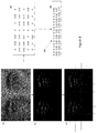
- the top row shows a sequence of images of a face captured with the same face at different distances from a camera ranging from 0.33 m to 2 m.
- the light level for capturing the images is similar ranging from 3.5 Lux to 2.5 Lux.
- the face region from each acquired image from the top row is scaled to a common size and in this case the upper half of the face region is chosen and scaled to provide a 200 ⁇ 100 pixel region of interest.
- the focus position of the camera lens is shifted by varying a code (DAC) for the lens actuator across its range from values, in this case from 1 to >61 and a sharpness measure is calculated for each position.
- DAC code
- a threshold absolute gradient contrast measure such as described above is used. Contrary to human perception, the sharpness measure across the range of focus positions provided for the most distant 2 m image is actually higher than for the largest well-lit face region acquired at 0.33 m. This is because the sharpness measures for the most distant image has been affected by noise.
- the sharpness measures for an image taken across a range of focus positions, both on focused and on defocused images, in good light (20 Lux) can be smaller than for those taken in low light (2.5 Lux), contrary to human perception, again because of the influence of noise within the image.
- the metric should be valid for varying light levels including very low light conditions where an acquired image may be quite noisy.
- the metric should be absolute so that a determination can be made directly from any given image whether it is sufficiently focussed or not i.e. the sharpness value for any well focused image should be higher than the sharpness level for any defocused image irrespective of an ambient luminance value.
- the sharpness measure decreases with the distance to the subject and with the ambient light level value in accordance with human perception.
- the ideal absolute sharpness function should be narrow enough in all cases i.e. it should have a distinct peak around the peak focus position.
- Embodiments of the invention can be used to track a ROI over a number of frames, maintaining correct focusing, even though the ROI may move within the image and be exposed with various lighting conditions.
- FIG. 1 shows a number of images including a face region acquired at different distances from a camera along with conventional type sharpness measures for each image;
- FIG. 2 shows a number of images acquired at the same distance but at different light levels along with conventional type sharpness measures for each image
- FIG. 3 is a flow diagram illustrating the calculation of a sharpness measure for a region of interest (ROI) of an image according to an embodiment of the present invention
- FIG. 4 shows the processing of FIG. 3 for an exemplar ROI of an image
- FIG. 5 shows a number of face regions from images acquired at different distances from a camera along with sharpness measures for each image provided according to an embodiment of the present invention.
- FIG. 6 shows a number of face regions from images acquired at different light levels along with sharpness measures for each image across a range of focus positions provided according to an embodiment of the present invention.
- FIG. 3 an embodiment of the present invention will now be described with reference to a ROI of interest of an image comprising an object comprising a face.
- the method begins by first identifying a region of interest (ROI) within an image, step 10 .
- ROI region of interest
- the ROI bounds a face.
- anthrometric information can be used to assist with the method such as knowing that the distance between eyes in an adult is approximately 7 cm as disclosed in PCT/EP2015/076881 (Ref: FN-399-PCT) or that the smallest size of face which might need to be focus tracked would measure approximately 200 ⁇ 200 pixels.
- the present invention is equally applicable to providing a sharpness measure for an image with a ROI containing any type of object with a view to trying to provide an absolute sharpness value for any given image reflecting human perception.
- the method acquires the metadata for the current object/frame.
- This includes, for example, ISO/Gain, exposure time, object ROI coordinates, object pixel values.
- Other meta-data which can be used within embodiments of the invention could involve indicators of object orientation. It will be appreciated that the characteristics exhibited by an object such as a face differ according to its orientation within an image, for example, a profile image will only include 1 eye and might contain proportionally more skin than a front facing face. Similarly faces which are identified under different illumination conditions (for example, using differently trained classifiers such as: top-lit, side-lit etc.) can exhibit different characteristics. This information can be used in variations of the embodiment disclosed below, for example, to vary parameters employed in the sharpness measure. On the other hand, some parameters can be set to take into account the characteristics of features such as the eyes, skin, face pattern, face geometry/dimensions implicitly as will be explained below.
- the upper part of the face region i.e. the portion containing the eyes is chosen as the ROI on which the sharpness measure will be calculated.
- the measure could be based on the complete face region.
- the upper part of the face may appear below or to the left/right of the lower part of the face—this is readily dealt with to ensure the portion containing the eyes is chosen.
- the face size for sharpness computation is chosen as 200 (width) ⁇ 100 (height) as, typically, this is the smallest face size which might be required for AF/sharpness evaluation.
- the selected upper part of the face region is scaled to a size of 200 ⁇ 100 to provide a ROI 40 such as shown in FIG. 4 .
- the constants used in the ISO, Luminance and Distance threshold calculations above normalize each component of the sharpness threshold relative to one another and are based on the face size chosen for sharpness computation. As such, these can vary if a region of interest with a size different than 200 ⁇ 100 were chosen. Thus for a larger ROI, these constants would increase (so reducing the sharpness measure as will be seen later).
- the present embodiment uses the average luminance value as a quick measure of the likely contrast range within an image—contrast tending to increase with increasing luminance values and so indicating higher noise levels within an image.
- other measures of contrast level within the ROI could be employed than using average luminance.
- using the ROI width as a measure of the distance to the subject involves minimal calculation and so speeds up this method.
- the above sharpness threshold also assumes that optimal focus position is being determined using preview images, prior to capturing a main image. Typically, exposure time for such images is maximal and so would not vary. On the other hand, if exposure time were to be less than maximal i.e. variable, then the sharpness threshold would be proportional to the exposure time component.
- a raw sharpness (gradient) map is provided by calculating a simple difference between the luminance channel (Y) values for the scaled 200 ⁇ 100 ROI and a version of the scaled 200 ⁇ 100 ROI shifted by 1 pixel to the right.
- Y luminance channel
- HOG histogram of gradients
- the resulting raw sharpness map is filtered by a simple thresholding where the sharpness threshold calculated at step 16 above is first subtracted from the gradient map values, step 20 .
- the filtered sharpness map might look like the map 42 .
- This method now takes advantage of the fact that an important percentage of the ROI contains relatively uniform skin regions, where the sharpness is expected to be low.
- the filtered gradient map is split into an array of generally equal sized cells.
- an array of 7 ⁇ 5 cells is employed.
- the mean sharpness of each cell is calculated as the average of the filtered gradient map values in each cell 24 .
- Sample values for the ROI, map and array 40 - 44 are shown in the array 46 of FIG. 4 .
- step 26 These values are next sorted in order of magnitude, step 26 , as shown in the list 48 .
- the values 50 for index [ 3 ] to index [ 13 ] within the ordered list 48 are selected and their average is chosen as an indicator of the noise level within the ROI 40 .
- a noise level of 0 is determined for the ROI 40 .
- a raw sharpness measure is calculated as the mean value of the filtered gradient map produced in step 20 less the noise level determined at step 28 .
- the raw sharpness measure can be normalized with respect to luminance by dividing the raw sharpness measure by the mean luminance for the ROI to provide a final sharpness value, step 32 .
- FIG. 5 illustrates the sharpness measure calculated according to the above embodiment for the faces shown in FIG. 1 i.e. the same face, taken in almost same ambient conditions where only the distance to the subject is varying. As can be seen, at 2 m the absolute sharpness values are smaller than at 0.33 m, similar to the human perception.
- FIG. 6 illustrates the sharpness measure calculated according to the above embodiment for the faces shown in FIG. 2 i.e. on faces at same distance at various ambient light levels. As will be seen, for good light, the sharpness measure is bigger than for images acquired in in low light, again similar to the human perception, and with a well-defined peak.
- the sharpness value for the focused images is higher than the sharpness values of the defocused images even when we compare the curves taken in different lighting conditions. This is again similar to the human perception.
- a second embodiment can improve the quality (from a human perception point of view) of the sharpness measure of the above described first embodiment for images of subjects at shorter distances (e.g. 300 mm-500 mm). Compared to images of subjects at longer distances (>1000 mm), a larger quantity of light lands on the image sensor for images of subjects at shorter distances. Thus, a wider range of lens positions tends to output similar sharpness levels, when the lens is near a desired shorter focus position.
- the image is split in 7 ⁇ 5 blocks 44 and the average illumination for each block is stored in an array 46 .
- the array values are then sorted in ascending order and a noise level is extracted at step 28 , using the 3 rd and 13 th elements of the sorted array (sorted_vals) 48 .
- the second embodiment takes into account all of the elements from the sorted array 48 and splits them into two categories:
- sharpness_ thr min([MAX_SHARPNESS_ TH ,(max(12 ,thr _ ISO+thr _Lum+ thr _Dist)+min(10 ,thr _Face*20))]);
Landscapes
- Engineering & Computer Science (AREA)
- Physics & Mathematics (AREA)
- General Physics & Mathematics (AREA)
- Theoretical Computer Science (AREA)
- Multimedia (AREA)
- Computer Vision & Pattern Recognition (AREA)
- Signal Processing (AREA)
- Quality & Reliability (AREA)
- Health & Medical Sciences (AREA)
- Human Computer Interaction (AREA)
- Oral & Maxillofacial Surgery (AREA)
- General Health & Medical Sciences (AREA)
- Probability & Statistics with Applications (AREA)
- Image Processing (AREA)
Abstract
Description
-
- A. Functions based on image differentiation such as:
- 1. Threshold absolute gradient
- A. Functions based on image differentiation such as:
-
-
-
- while |g(i,j+1)−g(i,j)|
- >thr, where g(i,j) is the gray level of pixel (i,j)
- while |g(i,j+1)−g(i,j)|
- 2. Tenengrad function
-
-
-
-
-
- where T[g(i,j)] is the square of the gradient value in pixels (i,j)
-
- B. Functions based on depth of peaks and valleys
- C. Functions based on image contrast
- D. Functions based on histogram
- E. Functions based on correlation measurements including:
- Vollath's F4 (based on the autocorrelation function, very good performance in presence of noise)
-
ISO Threshold (thr_ISO)=Meta Data ISO Value/250;
Luminance Threshold (thr_Lum)=Average luminance for pixels of the ROI/50;
Distance to subject threshold (thr_Dist)=ROI width/200;
Sharpness Threshold=max(12,thr_ISO+thr_Lum+thr_Dist).
-
- First 30 elements, from 1st to 30th (lowest values)—comprise residual information with a higher probability of containing noise and a lower probability of containing useful information (e.g. eyes)
- Last 6 elements, from 30th to 35th (highest values)—comprise useful information with a higher probability of containing information from the eye and eyebrow regions and with a lower probability for noise.
w b=0.1*(thr_Dist−(ISO Value/Average luminance)*0.01);
w r=1−w b;
thr_Face=mean(sorted_vals(30:35))*w b+mean(sorted_vals(1:30))*w r;
sharpness_thr=min([MAX_SHARPNESS_TH,(max(12,thr_ISO+thr_Lum+thr_Dist)+min(10,thr_Face*20))]);
raw_sharpness=max(0,(mean filtered gradient map−noise_level)*1000)
raw_sharpness=max(0,(mean filtered gradient map+thr_Face)*1000).
Claims (20)
thr_Face=mean(sorted_vals(high))*W b+mean(sorted_vals(low))*W r;
Wbαf(the distance to the subject)−(the ISO value/contrast level*d);
W r=1−W b; and d is a constant.
Priority Applications (2)
| Application Number | Priority Date | Filing Date | Title |
|---|---|---|---|
| US16/426,243 US10657628B2 (en) | 2017-03-01 | 2019-05-30 | Method of providing a sharpness measure for an image |
| US16/875,656 US11244429B2 (en) | 2017-03-01 | 2020-05-15 | Method of providing a sharpness measure for an image |
Applications Claiming Priority (3)
| Application Number | Priority Date | Filing Date | Title |
|---|---|---|---|
| US15/446,805 US20180253631A1 (en) | 2017-03-01 | 2017-03-01 | Method of providing a sharpness measure for an image |
| US15/872,873 US10311554B2 (en) | 2017-03-01 | 2018-01-16 | Method of providing a sharpness measure for an image |
| US16/426,243 US10657628B2 (en) | 2017-03-01 | 2019-05-30 | Method of providing a sharpness measure for an image |
Related Parent Applications (1)
| Application Number | Title | Priority Date | Filing Date |
|---|---|---|---|
| US15/872,873 Continuation US10311554B2 (en) | 2017-03-01 | 2018-01-16 | Method of providing a sharpness measure for an image |
Related Child Applications (1)
| Application Number | Title | Priority Date | Filing Date |
|---|---|---|---|
| US16/875,656 Continuation US11244429B2 (en) | 2017-03-01 | 2020-05-15 | Method of providing a sharpness measure for an image |
Publications (2)
| Publication Number | Publication Date |
|---|---|
| US20190279342A1 US20190279342A1 (en) | 2019-09-12 |
| US10657628B2 true US10657628B2 (en) | 2020-05-19 |
Family
ID=63357416
Family Applications (3)
| Application Number | Title | Priority Date | Filing Date |
|---|---|---|---|
| US15/872,873 Active US10311554B2 (en) | 2017-03-01 | 2018-01-16 | Method of providing a sharpness measure for an image |
| US16/426,243 Active US10657628B2 (en) | 2017-03-01 | 2019-05-30 | Method of providing a sharpness measure for an image |
| US16/875,656 Active US11244429B2 (en) | 2017-03-01 | 2020-05-15 | Method of providing a sharpness measure for an image |
Family Applications Before (1)
| Application Number | Title | Priority Date | Filing Date |
|---|---|---|---|
| US15/872,873 Active US10311554B2 (en) | 2017-03-01 | 2018-01-16 | Method of providing a sharpness measure for an image |
Family Applications After (1)
| Application Number | Title | Priority Date | Filing Date |
|---|---|---|---|
| US16/875,656 Active US11244429B2 (en) | 2017-03-01 | 2020-05-15 | Method of providing a sharpness measure for an image |
Country Status (1)
| Country | Link |
|---|---|
| US (3) | US10311554B2 (en) |
Families Citing this family (6)
| Publication number | Priority date | Publication date | Assignee | Title |
|---|---|---|---|---|
| US10902619B2 (en) * | 2016-10-26 | 2021-01-26 | Duke University | Systems and methods for determining quality metrics of an image or images based on an edge gradient profile and characterizing regions of interest in an image or images |
| CN110111261B (en) * | 2019-03-28 | 2021-05-28 | 瑞芯微电子股份有限公司 | Adaptive balance processing method for image, electronic device and computer readable storage medium |
| CN110740266B (en) * | 2019-11-01 | 2021-01-26 | Oppo广东移动通信有限公司 | Image frame selection method and device, storage medium and electronic equipment |
| CN112585941A (en) * | 2019-12-30 | 2021-03-30 | 深圳市大疆创新科技有限公司 | Focusing method and device, shooting equipment, movable platform and storage medium |
| US12035039B2 (en) | 2021-12-14 | 2024-07-09 | Capital One Services, Llc | Dynamic minimum focus threshold determination inside a region of interest in an image |
| KR20240159043A (en) * | 2023-04-28 | 2024-11-05 | 엘지전자 주식회사 | Display device and driving method thereof |
Citations (13)
| Publication number | Priority date | Publication date | Assignee | Title |
|---|---|---|---|---|
| US20050169531A1 (en) | 2004-01-30 | 2005-08-04 | Jian Fan | Image processing methods and systems |
| US20060251292A1 (en) | 2005-05-09 | 2006-11-09 | Salih Burak Gokturk | System and method for recognizing objects from images and identifying relevancy amongst images and information |
| US20080019661A1 (en) | 2006-07-18 | 2008-01-24 | Pere Obrador | Producing output video from multiple media sources including multiple video sources |
| US20080089561A1 (en) | 2006-10-11 | 2008-04-17 | Tong Zhang | Face-based image clustering |
| US20100303363A1 (en) | 2004-12-09 | 2010-12-02 | Fedorovskaya Elena A | Method for automatically determining the acceptability of a digital image |
| US20140078320A1 (en) | 2011-08-18 | 2014-03-20 | Nikon Corporation | Image sharpness classification system |
| US20140126804A1 (en) | 2012-11-05 | 2014-05-08 | Mitutoyo Corporation | Edge measurement video tool and interface including automatic parameter set alternatives |
| US20150269735A1 (en) | 2014-03-20 | 2015-09-24 | Canon Kabushiki Kaisha | Information processing apparatus, information processing method, position and orientation estimation apparatus, and robot system |
| WO2016000874A1 (en) | 2014-07-01 | 2016-01-07 | Fotonation Limited | A method for calibrating an image capture device |
| WO2016091545A1 (en) | 2014-12-09 | 2016-06-16 | Fotonation Limited | Image processing method |
| WO2017054941A1 (en) | 2015-09-30 | 2017-04-06 | Fotonation Limited | A method and system for tracking an object |
| US20170278289A1 (en) | 2016-03-22 | 2017-09-28 | Uru, Inc. | Apparatus, systems, and methods for integrating digital media content into other digital media content |
| US20180041754A1 (en) | 2016-08-08 | 2018-02-08 | Fotonation Limited | Image acquisition device and method |
Family Cites Families (6)
| Publication number | Priority date | Publication date | Assignee | Title |
|---|---|---|---|---|
| US6947784B2 (en) * | 2000-04-07 | 2005-09-20 | The General Hospital Corporation | System for digital bowel subtraction and polyp detection and related techniques |
| JP5229235B2 (en) * | 2007-12-25 | 2013-07-03 | 日本電気株式会社 | Image processing apparatus, image processing method, image expansion apparatus, image compression apparatus, image transmission system, and image processing program |
| TWI459821B (en) * | 2007-12-31 | 2014-11-01 | Altek Corp | Identification device of image feature pixel and its identification method |
| KR101810876B1 (en) * | 2012-03-13 | 2018-01-26 | 삼성전자주식회사 | A method and an apparatus for debluring non-uniform motion blur of a large scale input image based on a tile unit |
| US8724919B2 (en) * | 2012-09-21 | 2014-05-13 | Eastman Kodak Company | Adjusting the sharpness of a digital image |
| US9632679B2 (en) * | 2013-10-23 | 2017-04-25 | Adobe Systems Incorporated | User interface for managing blur kernels |
-
2018
- 2018-01-16 US US15/872,873 patent/US10311554B2/en active Active
-
2019
- 2019-05-30 US US16/426,243 patent/US10657628B2/en active Active
-
2020
- 2020-05-15 US US16/875,656 patent/US11244429B2/en active Active
Patent Citations (13)
| Publication number | Priority date | Publication date | Assignee | Title |
|---|---|---|---|---|
| US20050169531A1 (en) | 2004-01-30 | 2005-08-04 | Jian Fan | Image processing methods and systems |
| US20100303363A1 (en) | 2004-12-09 | 2010-12-02 | Fedorovskaya Elena A | Method for automatically determining the acceptability of a digital image |
| US20060251292A1 (en) | 2005-05-09 | 2006-11-09 | Salih Burak Gokturk | System and method for recognizing objects from images and identifying relevancy amongst images and information |
| US20080019661A1 (en) | 2006-07-18 | 2008-01-24 | Pere Obrador | Producing output video from multiple media sources including multiple video sources |
| US20080089561A1 (en) | 2006-10-11 | 2008-04-17 | Tong Zhang | Face-based image clustering |
| US20140078320A1 (en) | 2011-08-18 | 2014-03-20 | Nikon Corporation | Image sharpness classification system |
| US20140126804A1 (en) | 2012-11-05 | 2014-05-08 | Mitutoyo Corporation | Edge measurement video tool and interface including automatic parameter set alternatives |
| US20150269735A1 (en) | 2014-03-20 | 2015-09-24 | Canon Kabushiki Kaisha | Information processing apparatus, information processing method, position and orientation estimation apparatus, and robot system |
| WO2016000874A1 (en) | 2014-07-01 | 2016-01-07 | Fotonation Limited | A method for calibrating an image capture device |
| WO2016091545A1 (en) | 2014-12-09 | 2016-06-16 | Fotonation Limited | Image processing method |
| WO2017054941A1 (en) | 2015-09-30 | 2017-04-06 | Fotonation Limited | A method and system for tracking an object |
| US20170278289A1 (en) | 2016-03-22 | 2017-09-28 | Uru, Inc. | Apparatus, systems, and methods for integrating digital media content into other digital media content |
| US20180041754A1 (en) | 2016-08-08 | 2018-02-08 | Fotonation Limited | Image acquisition device and method |
Non-Patent Citations (4)
| Title |
|---|
| A. Santos, et al, "Evaluation of autofocus functions in molecular cytogenetic analysis", Journal of Microscopy, vol. 188, Pt 3, Dec. 1997, pp. 264-272. |
| Bhattacharjee D., Prakash S., Gupta P. (2012) "No-Reference Image Quality Assessment for Facial Images" In: Huang DS., Gan Y., Gupta P., Gromiha M.M. (eds) Advanced Intelligent Computing Theories and Applications. With Aspects of Artificial Intelligence. ICIC 2011. Lecture Notes in Computer Science, vol. 6839. Springer, Berlin, Heidelberg, pp. 594-601. |
| Gao X., Li S.Z., Liu R., Zhang P. (2007) Standardization of Face Image Sample Quality. In: Lee SW., Li S.Z. (eds) Advances in Biometrics. ICB 2007. Lecture Notes in Computer Science, vol. 4642. Springer, Berlin, Heidelberg, pp. 242-251. |
| Sang J., Lei Z., Li, S.Z. (2009) Face Image Quality Evaluation for ISO/IEC Standards 19794-5 and 29794-5. In: Tistarelli M., Nixon M.S. (eds) Advances in Biometrics. ICB 2009. Lecture Notes in Computer Science, vol. 5558. Springer, Berlin, Heidelberg, pp. 229-238. |
Also Published As
| Publication number | Publication date |
|---|---|
| US20190279342A1 (en) | 2019-09-12 |
| US10311554B2 (en) | 2019-06-04 |
| US20180253831A1 (en) | 2018-09-06 |
| US20200294206A1 (en) | 2020-09-17 |
| US11244429B2 (en) | 2022-02-08 |
Similar Documents
| Publication | Publication Date | Title |
|---|---|---|
| US10657628B2 (en) | Method of providing a sharpness measure for an image | |
| US9619708B2 (en) | Method of detecting a main subject in an image | |
| US9251439B2 (en) | Image sharpness classification system | |
| EP1225769B1 (en) | Spatial temporal visual attention model for a video frame sequence | |
| US8805112B2 (en) | Image sharpness classification system | |
| US20140079319A1 (en) | Methods for enhancing images and apparatuses using the same | |
| JP2004348674A (en) | Area detection method and device | |
| KR20100020903A (en) | Image identifying method and imaging apparatus | |
| CN101828201A (en) | Image processing device and method, and learning device, method, and program | |
| CN105243371A (en) | Human face beauty degree detection method and system and shooting terminal | |
| CN112037185A (en) | Chromosome split phase image screening method and device and terminal equipment | |
| Hua et al. | Impact of out-of-focus blur on face recognition performance based on modular transfer function | |
| CN105592258B (en) | Auto focusing method and device | |
| EP3745348B1 (en) | Image processing for removing fog or haze in images | |
| Petrović et al. | Evaluation of image fusion performance with visible differences | |
| CN111311562B (en) | Ambiguity detection method and device for virtual focus image | |
| CN112102141A (en) | Watermark detection method, watermark detection device, storage medium and electronic equipment | |
| CN111753642A (en) | Method and device for determining key frame | |
| JP4757598B2 (en) | Face detection method, apparatus, and program | |
| US20180253631A1 (en) | Method of providing a sharpness measure for an image | |
| CN106611417B (en) | Method and device for classifying visual elements into foreground or background | |
| US11631183B2 (en) | Method and system for motion segmentation | |
| CN112183454B (en) | Image detection method and device, storage medium and terminal | |
| CN115984921B (en) | Face mask recognition method and device, electronic device, storage medium | |
| Yousaf et al. | Approach to metric and discrimination of blur based on its invariant features |
Legal Events
| Date | Code | Title | Description |
|---|---|---|---|
| AS | Assignment |
Owner name: FOTONATION LIMITED, IRELAND Free format text: ASSIGNMENT OF ASSIGNORS INTEREST;ASSIGNORS:NANU, FLORIN;BOBEI, ADRIAN;MALAESCU, ALEXANDRU;AND OTHERS;REEL/FRAME:049318/0292 Effective date: 20180117 |
|
| FEPP | Fee payment procedure |
Free format text: ENTITY STATUS SET TO UNDISCOUNTED (ORIGINAL EVENT CODE: BIG.); ENTITY STATUS OF PATENT OWNER: LARGE ENTITY |
|
| STPP | Information on status: patent application and granting procedure in general |
Free format text: NON FINAL ACTION MAILED |
|
| STPP | Information on status: patent application and granting procedure in general |
Free format text: RESPONSE TO NON-FINAL OFFICE ACTION ENTERED AND FORWARDED TO EXAMINER |
|
| STPP | Information on status: patent application and granting procedure in general |
Free format text: NOTICE OF ALLOWANCE MAILED -- APPLICATION RECEIVED IN OFFICE OF PUBLICATIONS |
|
| STPP | Information on status: patent application and granting procedure in general |
Free format text: AWAITING TC RESP., ISSUE FEE NOT PAID |
|
| STPP | Information on status: patent application and granting procedure in general |
Free format text: PUBLICATIONS -- ISSUE FEE PAYMENT VERIFIED |
|
| STCF | Information on status: patent grant |
Free format text: PATENTED CASE |
|
| MAFP | Maintenance fee payment |
Free format text: PAYMENT OF MAINTENANCE FEE, 4TH YEAR, LARGE ENTITY (ORIGINAL EVENT CODE: M1551); ENTITY STATUS OF PATENT OWNER: LARGE ENTITY Year of fee payment: 4 |
|
| AS | Assignment |
Owner name: TOBII TECHNOLOGY LIMITED, IRELAND Free format text: CHANGE OF NAME;ASSIGNOR:FOTONATION LIMITED;REEL/FRAME:070238/0774 Effective date: 20240820 |
|
| AS | Assignment |
Owner name: TOBII TECHNOLOGIES LIMITED, IRELAND Free format text: CHANGE OF NAME;ASSIGNOR:FOTONATION LIMITED;REEL/FRAME:070682/0207 Effective date: 20240820 |
|
| AS | Assignment |
Owner name: BANK OF AMERICA, N.A., AS COLLATERAL AGENT, ILLINOIS Free format text: SECURITY INTEREST;ASSIGNORS:ADEIA INC. (F/K/A XPERI HOLDING CORPORATION);ADEIA HOLDINGS INC.;ADEIA MEDIA HOLDINGS INC.;AND OTHERS;REEL/FRAME:071454/0343 Effective date: 20250527 |
|
| AS | Assignment |
Owner name: ADEIA MEDIA HOLDINGS LLC, CALIFORNIA Free format text: ASSIGNMENT OF ASSIGNORS INTEREST;ASSIGNOR:TOBII TECHNOLOGIES LTD;REEL/FRAME:071572/0855 Effective date: 20250318 Owner name: ADEIA MEDIA HOLDINGS INC., CALIFORNIA Free format text: CONVERSION;ASSIGNOR:ADEIA MEDIA HOLDINGS LLC;REEL/FRAME:071577/0875 Effective date: 20250408 |