US1065641A - Lubricating device for car-axles. - Google Patents
Lubricating device for car-axles. Download PDFInfo
- Publication number
- US1065641A US1065641A US71388912A US1912713889A US1065641A US 1065641 A US1065641 A US 1065641A US 71388912 A US71388912 A US 71388912A US 1912713889 A US1912713889 A US 1912713889A US 1065641 A US1065641 A US 1065641A
- Authority
- US
- United States
- Prior art keywords
- oil
- axle
- spindle
- bearing
- car
- Prior art date
- Legal status (The legal status is an assumption and is not a legal conclusion. Google has not performed a legal analysis and makes no representation as to the accuracy of the status listed.)
- Expired - Lifetime
Links
- 230000001050 lubricating effect Effects 0.000 title description 6
- 230000002093 peripheral effect Effects 0.000 description 4
- 230000006872 improvement Effects 0.000 description 2
- 229910000897 Babbitt (metal) Inorganic materials 0.000 description 1
- 101150039167 Bex3 gene Proteins 0.000 description 1
- 238000010276 construction Methods 0.000 description 1
- 210000005069 ears Anatomy 0.000 description 1
- 230000005484 gravity Effects 0.000 description 1
- 239000000314 lubricant Substances 0.000 description 1
- 239000000463 material Substances 0.000 description 1
- 238000012986 modification Methods 0.000 description 1
- 230000004048 modification Effects 0.000 description 1
- 238000005192 partition Methods 0.000 description 1
Images

Classifications
-
- B—PERFORMING OPERATIONS; TRANSPORTING
- B61—RAILWAYS
- B61F—RAIL VEHICLE SUSPENSIONS, e.g. UNDERFRAMES, BOGIES OR ARRANGEMENTS OF WHEEL AXLES; RAIL VEHICLES FOR USE ON TRACKS OF DIFFERENT WIDTH; PREVENTING DERAILING OF RAIL VEHICLES; WHEEL GUARDS, OBSTRUCTION REMOVERS OR THE LIKE FOR RAIL VEHICLES
- B61F17/00—Lubrication specially adapted for axle-boxes of rail vehicles
- B61F17/02—Lubrication specially adapted for axle-boxes of rail vehicles with oil
- B61F17/04—Lubrication by stationary devices
- B61F17/12—Lubrication by stationary devices by gravity
Definitions
- Our invention relates to new and useful improvements in lubricating devices for car axles.
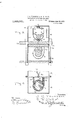
- Figure 1 is a vertical sectional view through an axle housing and bearing, and the mechanism employed by us for supplying lubricant thereto.
- Fig. 2 is a detail view of a portion of the mechanism as seen on line 22, Fig. 1.
- Fig. 3 is a detail sectional view as seen on line 3-3, Fig. 1.
- Fig. 4 is an elevation of a sleeve employed by us adapted to fit over a por tion of the axle.
- Fig. 5 is a transverse sectional view through an axle housing and lubricating device associated therewith, as seen on line 55, Fig. 1, and, Fig. 6 is a transverse sectional view throughone end of the device.
- Fig. 7 is a vertical sectional view of the slightly modified form of bearing for the reduced end of the axle, the same showing the form of roller bearing employed in connection with our lubricating device.
- FIG. 7 is an axle, which is provided at one end with a rigidly mounted wheel (not shown), the opposite end of the axle being provided with a reduced spindle 8.
- a sleeve 9 having an enlarged end 10 is placed upon the spindle and is adapted to receive thereon the usual form of car wheel 11.
- the enlarged end 10 of said sleeve is grooved as seen at 12, and said grooved portion is provided with a plurality of diagonally extending oil ducts 13, which extend from said groove toward the central portion of said sleeve, so that oil supplied to said sleeve in the manner hereinafter set forth will be conducted to the spindle.
- the sleeve 9 When the sleeve 9 has been placed upon the spindle it is adapted to be locked against longitudinal movement by means of a nut 14L, which is turned upon the threaded portion 15 intermediate the ends of said spindle, and said nut is locked in position in any desired manner, preferably by means of cotter pins 16, which extend through bores formed in said nut, and lit within grooves 17, formed in the sides of the threaded portion 15 of the spindle.
- the housing for the spindle end of the axle comprises a box 18 and a cover section 19.
- the spindle and the enlarged portion 10 of the sleeve extend through an opening inone end of the box 18 and said end of the box has secured thereto an oil reservoir 20, the lower surface of which is curved to fit the contour of the enlarged end 10.
- the sides of said reservoir have grooves therein adapted to receive the ends of a U-shaped yoke 21, which is formed to fit in the lower portion of the groove 12.
- the ends of the yoke 21 are secured within the grooves in the sides of the reservoir by means of bolts 22, or in any other desired manner.
- the bottom wall of the reservoir is provided with a plurality of oil holes 23, which are arranged in alinement with the groove 12 so that oil supplied to said reservoir will flow therefrom through said holes and into the grooves 12 and from thence will flow by way of oil ducts 13 to the spindle.
- the upper truck bar 2 which receives the weight of the car and truck frame, has its end extended transversely through openings 25 formed in the side of the box 18 and rests upon a plate 26, which in turn rests upon a bearing block 2'? formed of Babbitt metal, or other desired suitable material.
- the lower truck bar is extended beneath the box 18 and is secured to the upper truck bar 2 1 in any desired manner, as by means of bolts, as clearly shown in Fig. 5.
- the upper wall of the box 18 is cut away l the slot 28 and into engagement with a sec transversely, and portions thereof are bent up and engage with the sides of the truck bar 2%, so as to prevent relative movement of the box and truck-bar, and one end of said top wall is provided with a transverse slot 28, for a purpose hereinafter made clearly apparent.
- the truck bar 2%, plate 26 and bearing block 27 are provided with registering channels 29 and a tube 30 having a flared up per end 31 is inserted into the upper portion of the channel 29 in the truck bar 2% and the flared end extends into close engagement with the bottom wall of an oil reservoir 32.
- An oil tube $3 also extends through the upper wall of the box 18 and into communication with the oil reservoir 20, the flared upper end of said tube also fitting against the bottom wall of the oil receptacle 82.
- Said receptacle 32 is provided with openings 35 and 36, which register with the tubes 30 and 33, respectively.
- the oil receptacle 32 is mounted in the upper portion of the cover section or upper casing-section 19 and is held downwardly against the flared ends of the oil tubes by means of coil springs 37 interposed between the upper walls of said receptacle and chamber.
- fin oil feeding roller 38 is journaled in the end walls of the oil receptacle and is provided with a series of small cup-shaped depressions 3 arranged in alinement with the openings 35 and 86.
- the oil receptacle is provided with a pair of inwardly extending and downwardly directed flanges 10 which extend into close engagement with the periphery of the roller 38, as clearly shown in Fig. 5.
- the sides thereof With grooved blocks 4L1, which receive the edges of guides 1-2 secured to the sides of a cover 19.
- the top of the oil receptacle is provided with a filling opening 13 having an upwardly extending flange it therearound and is adapted to be normally closed by means of a cover pivotally secured to said top.
- the casing section 19 is also provided with a filling opening 16, which is adapted to be normally closed by a cover 47, pivotally secured to the casing section and said covers as and a? are connected and may be moved simultaneousl bv a am 18 a suitable slot .1 9
- the covers and their connecting pin are arranged so that the openings 43 and 16 will be uncovered or covered simultaneously.
- @ne of the stub-axles of the roller 38 extends through one end wall of the oil receptacle and has secured thereto a wheel 50, which is of sutlicient size to extend. through ond wheel 51, secured upon the end of the spindle 8.
- the end of the spindle 8 is reduced and is provided with a pair of ears 52, which lit into seats formed in the side of the disk 51.
- the reduced end of the spindle is screw threaded and adapted to receive a nut 58 thereon whereby the disl: 51 is locked in place.
- a roller bearing comprising a casing 54c having rollers 55 therein for supporting the sh aft 8.
- the upper wall of the casing 5 1- is provided with a channel 56 which is adapted to register, when the parts are assembled, with the channel 29 through. which oil is conducted to the spindle 8 from the oil receptacle 32.
- the upper portion of the oil receptacle 32 is filled with oil and, when the car is in operation and the wheels rotating, the oil feeding roller 38 will also be rotated, through the medium of the wheels 50 and 51, and the depressions 39 will each receive a quantity of oil and carry the same below the partitions 40, whereupon said quantities of oil will drop into the lower portion of the oil receptacle and gravitate through the openings and 36 and by way of the channel 29 and oil tubes 30 and 33, to the spindle of the axle and to the oil reservoir 20, respectively.
- oil reservoir means associated with the second said bearing for supporting the oil reservoir, said reservoir having an opening in communication with the peripheralgroove of the first said bearing, the first said bearing having a series of oil-ducts communicating with the peripheral-groove and with the axle, and a yoke having its medial portion fitted into the peripheral groove under the first said bearing and having its end portions secured to the reservoir.
Landscapes
- Chemical & Material Sciences (AREA)
- Oil, Petroleum & Natural Gas (AREA)
- Engineering & Computer Science (AREA)
- Mechanical Engineering (AREA)
- General Details Of Gearings (AREA)
Description
J. C. THOMPSON & G. W. HALL. LUBRIGATING DEVICE FOR GAR AXLES;
APPLICATION FILED AUG. 7, 1912. Patented June 24, 1913.
2 snnnrs-snsm 1.
COLUMBIA PLANOORAPH co., WASHINGTON. D. c.
J. G. THOMPSON & G. W. HALL. LUBRIGATING DEVICE FOR OAR AXLES.
APPLICATION FILED AUG. '1, 1912.
1,065,641 Patented June 24.1913.
2 SHEETSSHEET 2.
J, Q The mp$ev Meme/1 UNTTED %TATE% PATENT @FFTQE.
JU'ELL C. THOMPSON AND GEORGE W. HALL, OF BRAINEBD, MINNESOTA.
LUBRICATING DEVICE FOR CAR-AXLES.
Specification of Letters Patent.
Patented June 2 1, 1913.
Application filed August 7, 1912. Serial No. 713,889.
To aZZ whom, it may concern:
Be it known that we, JImLL C. THOMPSON and Gnoncn VJ. HALL, citizens of the United States, residing at Brainerd, in the county of Crow Wing and State of Minnesota, have invented certain new and useful Improve ments in Lubricating Devices for Car-Axles; and we do hereby declare the following to be a full, clear, and exact description of the in vention, such as will enable others skilled in the'art to which it appertains to make and use the same.
Our invention relates to new and useful improvements in lubricating devices for car axles.
parent in the specification and pointed out in the claims.
In the accompanying drawings we have shown the preferred form which our invention may take.
In said drawings, Figure 1 is a vertical sectional view through an axle housing and bearing, and the mechanism employed by us for supplying lubricant thereto. Fig. 2 is a detail view of a portion of the mechanism as seen on line 22, Fig. 1. Fig. 3 is a detail sectional view as seen on line 3-3, Fig. 1. Fig. 4: is an elevation of a sleeve employed by us adapted to fit over a por tion of the axle. Fig. 5 is a transverse sectional view through an axle housing and lubricating device associated therewith, as seen on line 55, Fig. 1, and, Fig. 6 is a transverse sectional view throughone end of the device. Fig. 7 is a vertical sectional view of the slightly modified form of bearing for the reduced end of the axle, the same showing the form of roller bearing employed in connection with our lubricating device.
Referring to the drawings by numerals of reference, similar numerals designating corresponding parts throughout the several views, 7 is an axle, which is provided at one end with a rigidly mounted wheel (not shown), the opposite end of the axle being provided with a reduced spindle 8. A sleeve 9 having an enlarged end 10 is placed upon the spindle and is adapted to receive thereon the usual form of car wheel 11. The enlarged end 10 of said sleeve is grooved as seen at 12, and said grooved portion is provided with a plurality of diagonally extending oil ducts 13, which extend from said groove toward the central portion of said sleeve, so that oil supplied to said sleeve in the manner hereinafter set forth will be conducted to the spindle. When the sleeve 9 has been placed upon the spindle it is adapted to be locked against longitudinal movement by means of a nut 14L, which is turned upon the threaded portion 15 intermediate the ends of said spindle, and said nut is locked in position in any desired manner, preferably by means of cotter pins 16, which extend through bores formed in said nut, and lit within grooves 17, formed in the sides of the threaded portion 15 of the spindle.
The housing for the spindle end of the axle comprises a box 18 and a cover section 19. The spindle and the enlarged portion 10 of the sleeve extend through an opening inone end of the box 18 and said end of the box has secured thereto an oil reservoir 20, the lower surface of which is curved to fit the contour of the enlarged end 10. The sides of said reservoir have grooves therein adapted to receive the ends of a U-shaped yoke 21, which is formed to fit in the lower portion of the groove 12. The ends of the yoke 21 are secured within the grooves in the sides of the reservoir by means of bolts 22, or in any other desired manner. The bottom wall of the reservoir is provided with a plurality of oil holes 23, which are arranged in alinement with the groove 12 so that oil supplied to said reservoir will flow therefrom through said holes and into the grooves 12 and from thence will flow by way of oil ducts 13 to the spindle.
The upper truck bar 2 1, which receives the weight of the car and truck frame, has its end extended transversely through openings 25 formed in the side of the box 18 and rests upon a plate 26, which in turn rests upon a bearing block 2'? formed of Babbitt metal, or other desired suitable material. The lower truck bar is extended beneath the box 18 and is secured to the upper truck bar 2 1 in any desired manner, as by means of bolts, as clearly shown in Fig. 5.
The upper wall of the box 18 is cut away l the slot 28 and into engagement with a sec transversely, and portions thereof are bent up and engage with the sides of the truck bar 2%, so as to prevent relative movement of the box and truck-bar, and one end of said top wall is provided with a transverse slot 28, for a purpose hereinafter made clearly apparent.
The truck bar 2%, plate 26 and bearing block 27 are provided with registering channels 29 and a tube 30 having a flared up per end 31 is inserted into the upper portion of the channel 29 in the truck bar 2% and the flared end extends into close engagement with the bottom wall of an oil reservoir 32. An oil tube $3 also extends through the upper wall of the box 18 and into communication with the oil reservoir 20, the flared upper end of said tube also fitting against the bottom wall of the oil receptacle 82. Said receptacle 32 is provided with openings 35 and 36, which register with the tubes 30 and 33, respectively.
The oil receptacle 32 is mounted in the upper portion of the cover section or upper casing-section 19 and is held downwardly against the flared ends of the oil tubes by means of coil springs 37 interposed between the upper walls of said receptacle and chamber. fin oil feeding roller 38 is journaled in the end walls of the oil receptacle and is provided with a series of small cup-shaped depressions 3 arranged in alinement with the openings 35 and 86. The oil receptacle is provided with a pair of inwardly extending and downwardly directed flanges 10 which extend into close engagement with the periphery of the roller 38, as clearly shown in Fig. 5.
In order that the oil reservoir may be maintained in. upright and central position and in close engagement with the oil tubes 30 and 33, we provide the sides thereof with grooved blocks 4L1, which receive the edges of guides 1-2 secured to the sides of a cover 19. The top of the oil receptacle is provided with a filling opening 13 having an upwardly extending flange it therearound and is adapted to be normally closed by means of a cover pivotally secured to said top. The casing section 19 is also provided with a filling opening 16, which is adapted to be normally closed by a cover 47, pivotally secured to the casing section and said covers as and a? are connected and may be moved simultaneousl bv a am 18 a suitable slot .1 9
49 being formed in the cover 19 to allow of the movement of said pin. The covers and their connecting pin are arranged so that the openings 43 and 16 will be uncovered or covered simultaneously.
@ne of the stub-axles of the roller 38 extends through one end wall of the oil receptacle and has secured thereto a wheel 50, which is of sutlicient size to extend. through ond wheel 51, secured upon the end of the spindle 8. As shown in the drawings the end of the spindle 8 is reduced and is provided with a pair of ears 52, which lit into seats formed in the side of the disk 51. The reduced end of the spindle is screw threaded and adapted to receive a nut 58 thereon whereby the disl: 51 is locked in place.
in 7 is disclosed a roller bearing comprising a casing 54c having rollers 55 therein for supporting the sh aft 8. The upper wall of the casing 5 1- is provided with a channel 56 which is adapted to register, when the parts are assembled, with the channel 29 through. which oil is conducted to the spindle 8 from the oil receptacle 32.
lVhen our invention is employed in use, the upper portion of the oil receptacle 32 is filled with oil and, when the car is in operation and the wheels rotating, the oil feeding roller 38 will also be rotated, through the medium of the wheels 50 and 51, and the depressions 39 will each receive a quantity of oil and carry the same below the partitions 40, whereupon said quantities of oil will drop into the lower portion of the oil receptacle and gravitate through the openings and 36 and by way of the channel 29 and oil tubes 30 and 33, to the spindle of the axle and to the oil reservoir 20, respectively.
In employing our invention upon the spindle of the opposite end of the axle from that shown, we dispense with the sleeve 9, the oil reservoir and the oil duct 38 and provide the bottom of the housing with the de' sired number of openings arranged in co1nmunication with channels extending to the bearing surface of the spindle.
By the construction herein shown it will be seen that the spindle of the axle will be continuously supplied with small quantities of oil and it will also be seen that the oil will be carried to the spindle only when the car is in motion. It will also be seen that the employment of a loose wheel upon the axle will allow the car to easily travel around curves, at which time the sleeve will rotate upon, the spindle.
l l hile we have shown the preferred form of our invention we desire to have it understood that certain modifications may be nade therein without departing from the spirit and scope of our invention.
What we claim as new is:
l. in combination with a rotatable axle, a peripherally grooved bearing surrounding the axle and adapted to rotate relative thereto and having a series of oil-ducts communicating with the peripheral. groove and with the axle and an oil reservoir having an opening in communication with the peripheral groove of the first said bearing, means for supporting the oil reservoir, and a yoke having its medial portion fitted into the peripheral groove under the first said bearing.
2. In combination with an axle and a bearing therefor, a casing above the axle and bearing, a vertically movable oilreceptacle in the casing and having an oil conduit communicating therewith and with the surface of the axle, an oil-feeding member rotatably mounted in the oil-receptacle, a gear wheel for actuating the oil-feeding members, a gear wheel operatively connecting the axle with the first said gear wheel, and resilient means for holding the oil-receptacle down and assisting gravity in retaining the gear wheels in operative relation.
3. In combination with a rotatable axle, a peripherally-grooved bearing surrounding the axle and adapted to rotate relative thereto, a second bearing stationary with relation to the axle and the first said bearing, an
oil reservoir, means associated with the second said bearing for supporting the oil reservoir, said reservoir having an opening in communication with the peripheralgroove of the first said bearing, the first said bearing having a series of oil-ducts communicating with the peripheral-groove and with the axle, and a yoke having its medial portion fitted into the peripheral groove under the first said bearing and having its end portions secured to the reservoir.
In testimony whereof we have signed our names to this specification in the presence of two subscribing witnesses.
JUELL G. THOMPSON. GEORGE WV. HALL.
Witnesses A. D. J oHNsoN, J. L. ELLIS.
Copies of this patent may be obtained for five cents each, by addressing the Commissioner of Patents, Washington, D. G.
Priority Applications (1)
| Application Number | Priority Date | Filing Date | Title |
|---|---|---|---|
| US71388912A US1065641A (en) | 1912-08-07 | 1912-08-07 | Lubricating device for car-axles. |
Applications Claiming Priority (1)
| Application Number | Priority Date | Filing Date | Title |
|---|---|---|---|
| US71388912A US1065641A (en) | 1912-08-07 | 1912-08-07 | Lubricating device for car-axles. |
Publications (1)
| Publication Number | Publication Date |
|---|---|
| US1065641A true US1065641A (en) | 1913-06-24 |
Family
ID=3133884
Family Applications (1)
| Application Number | Title | Priority Date | Filing Date |
|---|---|---|---|
| US71388912A Expired - Lifetime US1065641A (en) | 1912-08-07 | 1912-08-07 | Lubricating device for car-axles. |
Country Status (1)
| Country | Link |
|---|---|
| US (1) | US1065641A (en) |
-
1912
- 1912-08-07 US US71388912A patent/US1065641A/en not_active Expired - Lifetime
Similar Documents
| Publication | Publication Date | Title |
|---|---|---|
| US124227A (en) | Improvement in car-axle boxes | |
| US122219A (en) | Improvement in journal-boxes for railway cars | |
| US235162A (en) | maodonald | |
| US516311A (en) | Journal-box | |
| US41221A (en) | Improvement in journal-boxes | |
| US257582A (en) | Car-axle box | |
| US518157A (en) | Axle-lubricator | |
| US413771A (en) | Car-axle lubricator | |
| US1119584A (en) | Journal-box lubricator. | |
| US424350A (en) | Lubricator | |
| US70697A (en) | clemens | |
| US442631A (en) | Journal-box | |
| US1075761A (en) | Journal-box for railroad-cars. | |
| US238242A (en) | Giffoed j | |
| US121575A (en) | Improvement in lubricators for car-axles | |
| US227220A (en) | Car-axle box | |
| US459129A (en) | Oil-cup attachment for journal-boxes | |
| US52181A (en) | Improved railroad-car box | |
| US579909A (en) | Charles h | |
| US412233A (en) | Car-axle lubricator | |
| US337779A (en) | Car-axle lubricator | |
| US136472A (en) | Improvement in car-axle boxes | |
| US1914637A (en) | Journal lubricator | |
| US422011A (en) | Car-axle lubricator | |
| US187553A (en) | Improvement in car-axle lubricators |