US10655846B2 - Gas burner assembly for a cooktop appliance - Google Patents
Gas burner assembly for a cooktop appliance Download PDFInfo
- Publication number
- US10655846B2 US10655846B2 US15/706,838 US201715706838A US10655846B2 US 10655846 B2 US10655846 B2 US 10655846B2 US 201715706838 A US201715706838 A US 201715706838A US 10655846 B2 US10655846 B2 US 10655846B2
- Authority
- US
- United States
- Prior art keywords
- projections
- burner
- gas burner
- boost
- chamber
- Prior art date
- Legal status (The legal status is an assumption and is not a legal conclusion. Google has not performed a legal analysis and makes no representation as to the accuracy of the status listed.)
- Active, expires
Links
Images


Classifications
-
- F—MECHANICAL ENGINEERING; LIGHTING; HEATING; WEAPONS; BLASTING
- F23—COMBUSTION APPARATUS; COMBUSTION PROCESSES
- F23D—BURNERS
- F23D14/00—Burners for combustion of a gas, e.g. of a gas stored under pressure as a liquid
- F23D14/02—Premix gas burners, i.e. in which gaseous fuel is mixed with combustion air upstream of the combustion zone
- F23D14/04—Premix gas burners, i.e. in which gaseous fuel is mixed with combustion air upstream of the combustion zone induction type, e.g. Bunsen burner
- F23D14/06—Premix gas burners, i.e. in which gaseous fuel is mixed with combustion air upstream of the combustion zone induction type, e.g. Bunsen burner with radial outlets at the burner head
-
- F—MECHANICAL ENGINEERING; LIGHTING; HEATING; WEAPONS; BLASTING
- F23—COMBUSTION APPARATUS; COMBUSTION PROCESSES
- F23D—BURNERS
- F23D14/00—Burners for combustion of a gas, e.g. of a gas stored under pressure as a liquid
- F23D14/20—Non-premix gas burners, i.e. in which gaseous fuel is mixed with combustion air on arrival at the combustion zone
- F23D14/22—Non-premix gas burners, i.e. in which gaseous fuel is mixed with combustion air on arrival at the combustion zone with separate air and gas feed ducts, e.g. with ducts running parallel or crossing each other
- F23D14/24—Non-premix gas burners, i.e. in which gaseous fuel is mixed with combustion air on arrival at the combustion zone with separate air and gas feed ducts, e.g. with ducts running parallel or crossing each other at least one of the fluids being submitted to a swirling motion
-
- F—MECHANICAL ENGINEERING; LIGHTING; HEATING; WEAPONS; BLASTING
- F23—COMBUSTION APPARATUS; COMBUSTION PROCESSES
- F23D—BURNERS
- F23D14/00—Burners for combustion of a gas, e.g. of a gas stored under pressure as a liquid
- F23D14/46—Details
- F23D14/62—Mixing devices; Mixing tubes
-
- F—MECHANICAL ENGINEERING; LIGHTING; HEATING; WEAPONS; BLASTING
- F23—COMBUSTION APPARATUS; COMBUSTION PROCESSES
- F23D—BURNERS
- F23D2900/00—Special features of, or arrangements for burners using fluid fuels or solid fuels suspended in a carrier gas
- F23D2900/14—Special features of gas burners
- F23D2900/14021—Premixing burners with swirling or vortices creating means for fuel or air
-
- F—MECHANICAL ENGINEERING; LIGHTING; HEATING; WEAPONS; BLASTING
- F23—COMBUSTION APPARATUS; COMBUSTION PROCESSES
- F23D—BURNERS
- F23D2900/00—Special features of, or arrangements for burners using fluid fuels or solid fuels suspended in a carrier gas
- F23D2900/14—Special features of gas burners
- F23D2900/14062—Special features of gas burners for cooking ranges having multiple flame rings
-
- F—MECHANICAL ENGINEERING; LIGHTING; HEATING; WEAPONS; BLASTING
- F23—COMBUSTION APPARATUS; COMBUSTION PROCESSES
- F23N—REGULATING OR CONTROLLING COMBUSTION
- F23N1/00—Regulating fuel supply
- F23N1/002—Regulating fuel supply using electronic means
Definitions
- the present subject matter relates generally to cooktop appliances and more particularly to gas burner assemblies for cooktop appliances.
- Gas burners are commonly used on the cooktops of household gas cooking appliances including e.g., range ovens and cooktops built into cabinetry.
- gas cooktops traditionally have at least one gas burner positioned at a cooktop surface for use in heating or cooking an object, such as a cooking utensil and its contents.
- Control knobs are typically used to adjust the power level of the heating element, e.g., the amount of fuel directed to the burner, and thus the amount of heat delivered by the gas burner.
- Normally aspirated gas burners rely on the energy available in the form of pressure from the fuel supplied to the gas burner to entrain air for combustion. Because the nominal pressure in households is relatively low, there is a practical limit to the amount of primary air a normally aspirated gas burner can entrain. Introducing a fan or another forced air supply into a gas burner assembly may improve the mixture of fuel and air for improved operation at higher outputs, with shorter flames and improved stability, and with improved efficiency. Forced air burners often use tall, narrow, and closely spaced burner ports to minimize the burner footprint and flame lengths, thereby improving heat transfer efficiency.
- an improved gas burner assembly is desirable. More particularly, a gas burner assembly including an easily manufactured forced air burner having tall, narrow burner ports would be particularly beneficial.
- the present disclosure relates generally to a gas burner assembly for a cooktop appliance including a lower body and an upper body positioned over the lower body to define a boost burner chamber.
- a first plurality of projections extends upward from the lower body and a second plurality of projections extends downward from the upper body.
- the second plurality of projections are interposed between the first plurality of projections to define a plurality of burner ports in fluid communication with the boost burner chamber. In this manner, burner ports are easily manufactured and define a larger height-to-width aspect ratio for improved burner performance. Additional aspects and advantages of the invention will be set forth in part in the following description, or may be apparent from the description, or may be learned through practice of the invention.
- a gas burner assembly for a cooktop appliance includes a lower body and an upper body positioned over the lower body to define a boost burner chamber.
- a first plurality of projections is defined by the lower body and extends substantially upward along the axial direction.
- a second plurality of projections is defined by the upper body and extends substantially downward along the axial direction, the second plurality of projections being interposed between the first plurality of projections to define a plurality of burner ports in fluid communication with the boost burner chamber.
- a gas burner assembly positioned on a top panel of a cooktop appliance.
- the gas burner assembly includes a bottom housing defining an axial direction, a radial direction, and a circumferential direction.
- a center body is positioned concentrically within the bottom housing to define a mixing chamber therebetween, the center body further defining an inner chamber positioned inward of the mixing chamber along the radial direction and a plurality of apertures providing fluid communication between the mixing chamber and the inner chamber.
- An upper housing is positioned over the center body, the upper housing including a lower body positioned over the center body to define a primary burner chamber and an upper body positioned over the lower body to define a boost burner chamber in fluid communication with the inner chamber of the center body.
- a first plurality of projections is defined by the lower body and extends substantially upward along the axial direction.
- a second plurality of projections is defined by the upper body and extends substantially downward along the axial direction, the second plurality of projections being interposed between the first plurality of projections to define a plurality of burner ports in fluid communication with the boost burner chamber.
- FIG. 1 provides a top view of a cooktop appliance according to an exemplary embodiment of the present subject matter.
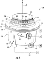
- FIG. 2 provides a perspective view of a gas burner assembly of the exemplary cooktop appliance of FIG. 1 according to an exemplary embodiment of the present subject matter.
- FIG. 3 provides a bottom perspective view of the exemplary gas burner assembly of FIG. 2 positioned within a top panel of the exemplary cooktop appliance of FIG. 1 .
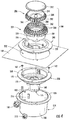
- FIG. 4 provides an exploded perspective view of the exemplary gas burner assembly of FIG. 2 .
- FIG. 5 provides a cross sectional view of the exemplary gas burner assembly of FIG. 2 .
- FIG. 6 provides a top perspective view of a bottom housing of the exemplary gas burner assembly of FIG. 2 with fuel and air inlets illustrated in phantom.
- FIG. 7 provides a bottom perspective view of a center body of the exemplary gas burner assembly of FIG. 2 .
- FIG. 8 provides an exploded, bottom perspective view of an upper housing of the exemplary gas burner assembly of FIG. 2 .
- FIG. 9 provides a cross sectional view of the exemplary upper housing of FIG. 8 , cut along two planes.
- FIG. 10 provides an exploded, cross sectional view of the exemplary upper housing of FIG. 8 , cut along two planes.
- the present disclosure relates generally to a gas burner assembly for a cooktop appliance 100 .
- cooktop appliance 100 is used below for the purpose of explaining the details of the present subject matter, one skilled in the art will appreciate that the present subject matter may apply to any other suitable consumer or commercial appliance.
- the exemplary gas burner assemblies described below may be used on other types of cooking appliances, such as ranges or oven appliances.
- Cooktop appliance 100 is used in the discussion below only for the purpose of explanation, and such use is not intended to limit the scope of the present disclosure in any manner.
- FIG. 1 illustrates an exemplary embodiment of a cooktop appliance 100 of the present disclosure.
- Cooktop appliance 100 may be, e.g., fitted integrally with a surface of a kitchen counter, may be configured as a slide-in cooktop unit, or may be a part of a free-standing range cooking appliance.
- Cooktop appliance 100 includes a top panel 102 that includes one or more heating sources, such as heating elements 104 for use in, e.g., heating or cooking.
- Top panel 102 refers to any upper surface of cooktop appliance 100 on which utensils may be heated and therefore food cooked.
- top panel 102 may be constructed of any suitably rigid and heat resistant material capable of supporting heating elements 104 , cooking utensils, and/or other components of cooktop appliance 100 .
- top panel 102 may be constructed of enameled steel, stainless steel, glass, ceramics, and combinations thereof.
- a user interface panel or control panel 106 is located within convenient reach of a user of cooktop appliance 100 .
- control panel 106 includes control knobs 108 that are each associated with one of heating elements 104 .
- Control knobs 108 allow the user to activate each heating element 104 and regulate the amount of heat input each heating element 104 provides to a cooking utensil located thereon, as described in more detail below.
- cooktop appliance 100 is illustrated as including control knobs 108 for controlling heating elements 104 , it should be understood that control knobs 108 and the configuration of cooktop appliance 100 shown in FIG. 1 is provided by way of example only. More specifically, control panel 106 may include various input components, such as one or more of a variety of touch-type controls, and/or electrical, mechanical or electro-mechanical input devices including rotary dials, push buttons, and touch pads.
- control knobs 108 are located within control panel 106 of cooktop appliance 100 .
- this location is used only for the purpose of explanation, and that other locations and configurations of control panel 106 and control knobs 108 are possible and within the scope of the present subject matter.
- control knobs 108 may instead be located directly on top panel 102 or elsewhere on cooktop appliance 100 , e.g., on a backsplash, front bezel, or any other suitable surface of cooktop appliance 100 .
- Control panel 106 may also be provided with one or more graphical display devices, such as a digital or analog display device designed to provide operational feedback to a user.
- cooktop appliance 100 is a gas cooktop and heating elements 104 are gas burners, such as gas burner assembly 150 described below. As illustrated, heating elements 104 are positioned within top panel 102 and have various sizes, as shown in FIG. 1 , so as to provide for the receipt of cooking utensils (e.g., pots, pans, etc.) of various sizes and configurations and to provide different heat inputs for such cooking utensils.
- cooktop appliance 100 may include one or more grates 110 configured to support a cooking utensil, such as a pot, pan, etc.
- grates 110 include a plurality of elongated members 112 , e.g., formed of cast metal, such as cast iron.
- the cooking utensil may be placed on the elongated members 112 of each grate 110 such that the cooking utensil rests on an upper surface of elongated members 112 during the cooking process.
- Heating elements 104 are positioned underneath the various grates 110 such that heating elements 104 provide thermal energy to cooking utensils above top panel 102 by combustion of fuel below the cooking utensils.
- cooktop appliance 100 includes a variety of control elements for regulating the amount of heat generated by heating elements 104 .
- heating element 104 is a gas burner assembly 150 that uses one or more flows of fuel and one or more flows of air for combustion.
- cooktop appliance 100 includes fuel control valves 120 and fuel lines 122 for supplying a metered amount of fuel to heating element 104 .
- Fuel lines 122 extend between control valves 120 and one or more fuel orifices of heating element 104 .
- fuel such as propane or natural gas may flow through fuel lines 122 to the fuel orifices for combustion.
- cooktop appliance 100 includes a forced air supply 124 and an air regulator 126 for controlling the amount of forced air introduced to heating element 104 for combustion.
- forced air supply 124 may be a fan, an air compressor, or any other suitable source of air.
- Cooktop appliance 100 may further include features for assisting mixing of air and fuel as the fuel enters heating element 104 , e.g., injectors, Venturi mixers, etc.
- fuel control valves 120 are each coupled to a respective one of control knobs 108 , Thus, a user may adjust fuel control valves 120 with control knobs 108 , thereby regulating fuel flow to heating elements 104 .
- air regulator 126 may be either directly controlled by control knob 108 or may be controlled based on the amount of fuel supplied to obtain the desired air/fuel ratio for combustion.
- some or all of these control components may be mounted to panel top 102 , e.g., on a bottom surface or underside of top panel 102 .
- gas burner assembly 150 that may be used with cooktop appliance 100 will be described in more detail.
- gas burner assembly 150 may be positioned elsewhere within cooktop appliance 100 , may have different components or configurations, and use alternative mechanisms for mixing fuel and air for combustion.
- Other variations and modifications of the exemplary embodiment described below are possible, and such variations are contemplated as within the scope of the present subject matter.
- gas burner assembly 150 generally defines an axial direction A, a radial direction R, and a circumferential direction C (see FIG. 5 ). As illustrated, gas burner assembly 150 is mounted within an aperture 152 defined in top panel 102 of cooktop appliance 100 . More specifically, gas burner assembly 150 includes a bottom housing 154 that defines a bottom flange 156 and is generally positioned below top panel 102 and a center body 158 that defines a top flange 160 which is generally positioned above top panel 102 .
- gas burner assembly 150 is installed in aperture 152 by joining bottom housing 154 and center body 158 using any suitable mechanical fastener 162 , such as screws, bolts, rivets, etc.
- any suitable mechanical fastener 162 such as screws, bolts, rivets, etc.
- glue, bonding, snap-fit mechanisms, interference-fit mechanisms, or any suitable combination thereof may be used to join bottom housing 154 and center body 158 .
- bottom housing 154 includes a bottom wall 164 and a side wall 166 which is generally cylindrically shaped and defines an open top.
- center body 158 generally includes a cylindrical lower wall 168 that defines an inner chamber 170 and an upper wall 172 that extends along the radial direction R out to top flange 160 .
- Center body 158 is mounted within bottom housing 154 such that it is positioned concentrically within bottom housing 154 to define an annular mixing chamber 174 , e.g., positioned between lower wall 168 and cylindrical wall 166 .
- annular mixing chamber 174 e.g., positioned between lower wall 168 and cylindrical wall 166 .
- inner chamber 170 is positioned inward of mixing chamber 174 along the radial direction R to define two separate chambers.
- lower wall 168 of center body 158 defines a plurality of apertures 176 providing fluid communication between mixing chamber 174 and inner chamber 170 .
- Mixing chamber 174 and inner chamber 170 are generally configured for receiving a flow of air and a flow of fuel and fully premixing them into a homogenous fuel mixture prior to combustion.
- bottom housing 154 defines a boost fuel inlet 180 and a boost air inlet 182 that are each in fluid communication with mixing chamber 174 .
- Boost fuel inlet 180 and boost air inlet 182 provide a flow of fuel and forced air, respectively, into mixing chamber 174 .
- boost fuel inlet 180 and boost air inlet 182 are positioned proximate a top of mixing chamber 174 , e.g., adjacent upper wall 172 , and the plurality of apertures 176 are defined proximate a bottom of mixing chamber 174 , e.g., as slots or openings defined by a distal end of lower wall 168 .
- fuel and air injected into mixing chamber 174 travels circumferentially within mixing chamber 174 around lower wall 168 as it migrates towards bottom wall 164 where it enters inner chamber 170 through apertures 176 .
- bottom housing 154 includes a variety of features to facilitate proper mixing of fuel and air for combustion.
- boost fuel inlet 180 may terminate in a spray nozzle 183 (see FIGS. 4 and 5 ) for directing the flow of fuel as desired.
- boost fuel inlet 180 injects a flow of fuel along a first direction 184 and boost air inlet 182 injects a flow of air along a second direction 186 .
- second direction 186 is substantially perpendicular to first direction 184 . More specifically, first direction 184 and second direction 186 define an intersection angle 188 of approximately 90 degrees. It should be appreciated that intersection angle 188 may vary according to alternative embodiments.
- first direction 184 is substantially parallel to the axial direction A such that fuel is injected upward and second direction 186 extends tangentially from cylindrical wall 166 such that boost air inlet 182 discharges air tangentially.
- boost fuel inlet 180 and boost air inlet 182 are illustrated as being positioned proximate to each other on bottom housing 154 such that the flow of air and fuel have high velocity when they begin mixing. The interaction between the two flows results in a desirable swirling motion within mixing chamber 174 and results in high turbulence and extended residence time.
- center body 158 also includes features to facilitate proper mixing of fuel and air for combustion.
- apertures 176 extend through center body 158 at an angle 190 relative to the radial direction R.
- Angle 190 may be selected to reduce drag on the flow of fuel and air and/or to continue swirling the flows for improved mixing.
- cooktop appliance 100 further includes an upper housing assembly or upper housing 200 positioned over center body 158 along the axial direction A.
- Upper housing 200 may include one or more components for receiving and conditioning one or more flows of fuel and air and passing it to various flame ports defined by upper housing 200 .
- upper housing 200 includes a burner seat 202 , a lower body 204 , and an upper body 206 that are generally stacked along the axial direction A. When assembled, upper housing 200 defines both a primary burner and a boost burner, which will be described in more detail below.
- upper housing 200 defines a primary burner chamber 210 , or more specifically, lower body 204 is positioned over burner seat 202 to define a primary burner chamber 210 therebetween.
- a primary fuel inlet 212 is in fluid communication with primary burner chamber 210 for providing a flow of fuel into primary burner chamber 210 . More specifically, as illustrated in FIGS. 4 through 7 , primary fuel inlet 212 passes from bottom wall 164 of bottom housing 154 along the axial direction A through mixing chamber 174 . Primary fuel inlet 212 then passes through an aperture 214 ( FIG. 7 ) defined in upper wall 172 of center body 158 and terminates in a spray nozzle 216 within an air entrainment chamber 218 defined between upper wall 172 and burner seat 202 of upper housing 200 .
- Air entrainment chamber 218 is in fluid communication with a primary air inlet 220 that extends about the circumferential direction C above top panel 102 of cooktop appliance 100 . More specifically, primary air inlet 220 is defined between upper wall 172 of center body 158 and burner seat 202 of upper housing 200 . In this manner, fresh primary supply air may be drawn from ambient air through primary air inlet 220 into air entrainment chamber 218 , in addition, as best shown in FIG. 5 , air entrainment chamber 218 is separated from primary burner chamber 210 by a divider wall 222 that extends along the radial direction R and is part of burner seat 202 . Divider wall 222 defines an aperture 224 (see FIG.
- a cylindrical channel 226 extends around aperture 224 and toward lower body 204 of upper housing 200 .
- cylindrical channel 226 terminates proximate a top of primary burner chamber 210 , i.e., adjacent lower body 204 of upper housing 200 .
- cylindrical channel 226 discharges a mixture of fuel and air proximate a top of primary burner chamber 210 .
- lower body 204 of upper housing 200 defines a circumferential baffle 230 that is positioned within primary burner chamber 210 and extends down along the axial direction A toward burner seat 202 to define an annular opening 232 proximate a bottom of primary burner chamber 210 .
- Upper housing 200 also defines a plurality of primary flame ports 234 spaced about the circumferential direction C and in fluid communication with primary burner chamber 210 via annular opening 232 . More specifically, primary flame ports 234 are defined between lower body 204 and burner seat 202 of upper housing 200 . In this manner, primary flame ports 234 are positioned below a plurality of boost burner ports 240 along the axial direction A, as will be described in detail below.
- gas burner assembly 150 further includes a boost burner.
- the primary burner is a normally aspirated burner that may be regulated for normal operation while the boost burner is a discretely operating (i.e., on or off) auxiliary forced air burner intended for performing high heat operations such as boiling a large pot of water.
- the primary burner and boost burner may both be incrementally regulated simultaneously or independently of each other according to alternative embodiments.
- upper housing 200 generally defines a boost burner chamber 238 ( FIG. 5 ) that extends along the axial direction A and is in fluid communication with inner chamber 170 of center body 158 . More specifically, upper body 206 is positioned over lower body 204 along the axial direction A to define boost burner chamber 238 . In this manner, boost burner chamber 238 receives a flow of boost fuel from boost fuel inlet 180 and of boost air from boost air inlet 182 .
- boost burner ports 240 spaced about the circumferential direction C and in fluid communication with boost burner chamber 238 .
- Boost burner ports 240 will be described in more detail below.
- a top cap 242 is positioned on top of upper body 206 to provide a clean appearance to gas burner assembly 150 and to help disperse the fuel mixture around boost burner ports 240 .
- upper body 206 defines a center boss 244 configured for receiving a spindle 246 extending from top cap 242 .
- Gas burner assembly 150 further includes a flow developer 250 for straightening the flow of fuel mixture prior to passing through boost burner ports 240 .
- lower body 204 defines flow developer 250 which is positioned between inner chamber 170 and boost burner chamber 238 for straightening or conditioning a flow of mixed fuel and air.
- flow developer 250 could be defined by center body 158 or could be a separate component according to alternative embodiments.
- flow developer 250 includes a plurality of conduits or passageways 252 that extend generally along the axial direction A between inner chamber 170 and boost burner chamber 238 .
- flow developer 250 may include a plurality of fins extending along the axial direction A or any other flow straightening structure.
- first projections 260 extend substantially upward along the axial direction A, i.e., toward upper body 206 . More specifically, for example, first projections 260 extend from a top surface 262 of lower body 204 .
- second projections 264 are defined by upper body 206 and extend substantially downward along the axial direction A, e.g., toward lower body 204 . More specifically, for example, second projections 264 extend from a bottom surface 266 of upper body 206 .
- terms of approximation such as “approximately,” “substantially,” or “about,” refer to being within a ten percent margin of error.
- second projections 264 are interposed between first projections 260 to define boost flame ports or boost burner ports 240 which are in fluid communication with boost burner chamber 238 .
- projections 260 , 264 alternate between each other around the circumferential direction C.
- first projections 260 may extend proximate to, or be in contact with, upper body 206 .
- second projections 264 may extend proximate to, or be in contact with, lower body 204 .
- each of the plurality of boost burner ports 240 are defined at least in part by top surface 262 , one of first projections 260 , bottom surface 266 , and one of second projections 264 .
- each of the plurality of boost burner ports 240 define a port height 270 that is measured along the axial direction A between top surface 262 of lower body 204 and bottom surface 266 of upper body 206 .
- each of the plurality, of boost burner ports 240 define a port width 272 (see FIG. 2 ) that is measured along the circumferential direction C between adjacent projections 260 , 264 which define that boost burner port 240 .
- port width 272 may be measured as a maximum width of each boost burner port 240 .
- port width 272 may instead refer to an average width, a minimum width, a width at a specific axial location of boost burner port 240 , etc.
- boost burner ports 240 define an aspect ratio, which is equivalent to the port height 270 over the port width 272 , which is greater than two to one. According to still other embodiments, the aspect ratio is greater than six to one or greater than ten to one.
- the port width 272 of at least one of the plurality of boost burner ports 240 is approximately two millimeters and the port height 270 is approximately ten millimeters or more.
- the port width 272 may be less than two millimeters.
- the ability to easily manufacture upper housing 200 such that boost burner ports 240 are so narrow is achieved by manufacturing lower body 204 and upper body 206 separately and then joining them together with interwoven projections 260 , 264 to define the boost burner ports 240 .
- first projections 260 and second projections 264 may define a projection width 274 measured along the circumferential direction C. More specifically, projection width 274 may be measured as a maximum width of each projection 260 , 264 .
- projection width 274 may instead refer to an average width, a minimum width, a width at a specific axial location of projections 260 , 264 , etc.
- the projection width 274 may be less than 1.5 times the port width 272 of at least one of the plurality of boost burner ports 240 . In this regard, continuing the example from above, if the port width 272 is two millimeters, the projection width 274 may be 3 millimeters or less according to an exemplary embodiment.
- lower body 204 and upper body 206 may include various features for ensuring that second projections 264 are properly positioned or interwoven with first projections 260 .
- lower body 204 defines one or more alignment features
- upper body 206 defines one or more complementary features configured for engaging the alignment features to properly position upper body 206 over lower body 204 .
- the alignment features include an indentation 280 defined by lower body 204 between two of first projections 260 and the complementary features include a protrusion 282 extending from one or more of second projections 264 .
- Protrusion 282 is configured for receipt within indentation 280 to center each of second projections 264 between two adjacent first projections 260 .
- lower body 204 is illustrated as defining indentations 280 between each of first projections 260 and upper body 206 is illustrated as defining protrusions 282 on each of the second plurality of projections 264 , it should be appreciated that any suitable number, size, or position of alignment or indexing features may be used according to alternative embodiments.
- Lower body 204 and upper body 206 may define any suitable number and size of projections 260 , 264 to achieve the desired size and shape of boost burner ports 240 .
- first projections 260 and second projections 264 may each include greater than twenty projections.
- first projections 260 and second projections 264 may each include greater than about thirty projections.
- lower body 204 , upper body 206 , and their defined projections 260 , 264 may be formed using any suitable process.
- at least one of lower body 204 and upper body 206 are formed by a die casting process, a forging process, or any other suitable manufacturing method.
- gas burner assembly 150 in addition to the configurations of gas burner assembly 150 described herein, alternative configurations of gas burner assembly 150 are possible and within the scope of the present subject matter.
- the size, positioning, and configuration of bottom housing 154 , center body 158 , and upper housing 200 may vary, the various fuel and air mixing chambers may be positioned differently, and other mixing features or configurations may be used. It should be appreciated that still other configurations are possible and within the scope of the present subject matter.
Landscapes
- Engineering & Computer Science (AREA)
- Chemical & Material Sciences (AREA)
- Combustion & Propulsion (AREA)
- Mechanical Engineering (AREA)
- General Engineering & Computer Science (AREA)
- Gas Burners (AREA)
Abstract
Description
Claims (20)
Priority Applications (1)
| Application Number | Priority Date | Filing Date | Title |
|---|---|---|---|
| US15/706,838 US10655846B2 (en) | 2017-09-18 | 2017-09-18 | Gas burner assembly for a cooktop appliance |
Applications Claiming Priority (1)
| Application Number | Priority Date | Filing Date | Title |
|---|---|---|---|
| US15/706,838 US10655846B2 (en) | 2017-09-18 | 2017-09-18 | Gas burner assembly for a cooktop appliance |
Publications (2)
| Publication Number | Publication Date |
|---|---|
| US20190086077A1 US20190086077A1 (en) | 2019-03-21 |
| US10655846B2 true US10655846B2 (en) | 2020-05-19 |
Family
ID=65720029
Family Applications (1)
| Application Number | Title | Priority Date | Filing Date |
|---|---|---|---|
| US15/706,838 Active 2038-03-01 US10655846B2 (en) | 2017-09-18 | 2017-09-18 | Gas burner assembly for a cooktop appliance |
Country Status (1)
| Country | Link |
|---|---|
| US (1) | US10655846B2 (en) |
Families Citing this family (1)
| Publication number | Priority date | Publication date | Assignee | Title |
|---|---|---|---|---|
| US20200032997A1 (en) * | 2018-07-25 | 2020-01-30 | Haier Us Appliance Solutions, Inc. | Gas burner with a compact injet |
Citations (13)
| Publication number | Priority date | Publication date | Assignee | Title |
|---|---|---|---|---|
| US2805710A (en) * | 1951-03-13 | 1957-09-10 | Brumbaugh Isaac Vernon | Gas burner |
| US5209217A (en) * | 1992-07-24 | 1993-05-11 | Maytag Corporation | Downdraft gas range with dual mode burner system |
| US5690483A (en) * | 1996-07-17 | 1997-11-25 | Eaton Coporation | Gaseous fuel burner |
| CA2307647A1 (en) * | 1997-10-20 | 1999-04-29 | Thermador Corporation | Plurality fingered burner |
| US5915956A (en) | 1996-03-18 | 1999-06-29 | Kwiatek; David J. | Gaseous fuel burner with reduced velocity flame generating ports |
| CN2718400Y (en) * | 2004-04-29 | 2005-08-17 | 韩锡忠 | Reinforced blowing compressing impact burner |
| EP2072900A1 (en) * | 2007-12-17 | 2009-06-24 | CANDY S.p.A. | Burner for a household gas cooktop and household gas cooktop |
| US20110108016A1 (en) * | 2009-11-06 | 2011-05-12 | Timothy Scott Shaffer | Burner for cooking appliances |
| WO2013183981A1 (en) * | 2012-06-08 | 2013-12-12 | Rivera Garza Jorge | Gaseous fuel burner with high energy and combustion efficiency, low pollutant emission and increased heat transfer |
| CN103900103A (en) | 2014-04-16 | 2014-07-02 | 上海禾森机电有限公司 | Blowing-type burner control method |
| US8845326B2 (en) | 2010-10-13 | 2014-09-30 | General Electric Company | Gas burner assembly |
| CN204438127U (en) | 2014-12-25 | 2015-07-01 | 浙江苏泊尔家电制造有限公司 | A kind of burner with high efficiency |
| JP6062509B2 (en) | 2011-09-23 | 2017-01-18 | ケィティ、コーポレーションKt Corporation | Merge candidate block guidance method and apparatus using such method |
-
2017
- 2017-09-18 US US15/706,838 patent/US10655846B2/en active Active
Patent Citations (15)
| Publication number | Priority date | Publication date | Assignee | Title |
|---|---|---|---|---|
| US2805710A (en) * | 1951-03-13 | 1957-09-10 | Brumbaugh Isaac Vernon | Gas burner |
| US5209217A (en) * | 1992-07-24 | 1993-05-11 | Maytag Corporation | Downdraft gas range with dual mode burner system |
| US5915956A (en) | 1996-03-18 | 1999-06-29 | Kwiatek; David J. | Gaseous fuel burner with reduced velocity flame generating ports |
| US5690483A (en) * | 1996-07-17 | 1997-11-25 | Eaton Coporation | Gaseous fuel burner |
| CA2307647A1 (en) * | 1997-10-20 | 1999-04-29 | Thermador Corporation | Plurality fingered burner |
| CN2718400Y (en) * | 2004-04-29 | 2005-08-17 | 韩锡忠 | Reinforced blowing compressing impact burner |
| EP2072900A1 (en) * | 2007-12-17 | 2009-06-24 | CANDY S.p.A. | Burner for a household gas cooktop and household gas cooktop |
| US20110108016A1 (en) * | 2009-11-06 | 2011-05-12 | Timothy Scott Shaffer | Burner for cooking appliances |
| US8381714B2 (en) | 2009-11-06 | 2013-02-26 | General Electric Company | Burner for cooking appliances |
| US8845326B2 (en) | 2010-10-13 | 2014-09-30 | General Electric Company | Gas burner assembly |
| JP6062509B2 (en) | 2011-09-23 | 2017-01-18 | ケィティ、コーポレーションKt Corporation | Merge candidate block guidance method and apparatus using such method |
| WO2013183981A1 (en) * | 2012-06-08 | 2013-12-12 | Rivera Garza Jorge | Gaseous fuel burner with high energy and combustion efficiency, low pollutant emission and increased heat transfer |
| CN103900103A (en) | 2014-04-16 | 2014-07-02 | 上海禾森机电有限公司 | Blowing-type burner control method |
| CN103900103B (en) | 2014-04-16 | 2016-01-06 | 上海禾森机电有限公司 | A kind of control method of air blast burner |
| CN204438127U (en) | 2014-12-25 | 2015-07-01 | 浙江苏泊尔家电制造有限公司 | A kind of burner with high efficiency |
Non-Patent Citations (4)
| Title |
|---|
| "Machine Translation of CN2718400Y". * |
| "Machine Translation of WO2013183981A1". * |
| Gollahalli, S R. "Jet flames from noncircular burners". Sadhana, vol. 22, Part 3. Jun. 1997. * |
| Jones, H. R. N. "The Application of Combustion Principles to Domestic Gas Burner Design". Taylor & Francis, 1989. * |
Also Published As
| Publication number | Publication date |
|---|---|
| US20190086077A1 (en) | 2019-03-21 |
Similar Documents
| Publication | Publication Date | Title |
|---|---|---|
| US10823402B2 (en) | Gas burner assembly for a cooktop appliance | |
| US10041683B2 (en) | Gas burner assembly for a cooktop appliance | |
| KR20170127019A (en) | Bottom cup covers and burners and gas appliances | |
| US10480794B2 (en) | Cooktop appliance with a gas burner assembly | |
| US10753617B2 (en) | Cooktop appliance with a gas burner assembly | |
| US10677469B2 (en) | Fuel supply system for a gas burner assembly | |
| US11098892B2 (en) | Dual venturi single chamber gas burner | |
| US20190120496A1 (en) | Fuel supply system for a gas burner assembly | |
| US20140190467A1 (en) | Multi-ring gas burner for an appliance | |
| US10330326B2 (en) | Gas burner assembly for a cooktop appliance | |
| US11988391B2 (en) | Pan support, gas hob and method for producing a pan support | |
| CN111936791B (en) | Pan support, gas stove and method for producing a pan support | |
| US10393387B2 (en) | Gas burner assembly for a cooktop appliance | |
| CN101641554B (en) | heating cooking utensils | |
| CN106122961A (en) | Burner assembly and gas-cooker | |
| US10655846B2 (en) | Gas burner assembly for a cooktop appliance | |
| US11085645B2 (en) | Eductor for a gas cooktop appliance | |
| US11519606B1 (en) | Burner with an optional pilot | |
| US11460190B2 (en) | Gas burner assembly for a cooktop appliance | |
| CN112178640A (en) | an infrared burner | |
| US11592174B2 (en) | Gas burner with a pneumatic actuating injet | |
| US11454393B2 (en) | Gas burner with an offset flame port array | |
| US20190086078A1 (en) | Gas burner assembly for a cooktop appliance | |
| US10746396B2 (en) | Gas burner for a cooktop appliance | |
| CN116085833B (en) | An integrated stove |
Legal Events
| Date | Code | Title | Description |
|---|---|---|---|
| AS | Assignment |
Owner name: HAIER US APPLIANCE SOLUTIONS, INC., DELAWARE Free format text: ASSIGNMENT OF ASSIGNORS INTEREST;ASSIGNOR:CADIMA, PAUL BRYAN;REEL/FRAME:043611/0019 Effective date: 20170913 |
|
| FEPP | Fee payment procedure |
Free format text: ENTITY STATUS SET TO UNDISCOUNTED (ORIGINAL EVENT CODE: BIG.); ENTITY STATUS OF PATENT OWNER: LARGE ENTITY |
|
| STPP | Information on status: patent application and granting procedure in general |
Free format text: DOCKETED NEW CASE - READY FOR EXAMINATION |
|
| STPP | Information on status: patent application and granting procedure in general |
Free format text: NON FINAL ACTION MAILED |
|
| STPP | Information on status: patent application and granting procedure in general |
Free format text: RESPONSE TO NON-FINAL OFFICE ACTION ENTERED AND FORWARDED TO EXAMINER |
|
| STPP | Information on status: patent application and granting procedure in general |
Free format text: FINAL REJECTION MAILED |
|
| STPP | Information on status: patent application and granting procedure in general |
Free format text: RESPONSE AFTER FINAL ACTION FORWARDED TO EXAMINER |
|
| STPP | Information on status: patent application and granting procedure in general |
Free format text: NOTICE OF ALLOWANCE MAILED -- APPLICATION RECEIVED IN OFFICE OF PUBLICATIONS |
|
| STPP | Information on status: patent application and granting procedure in general |
Free format text: PUBLICATIONS -- ISSUE FEE PAYMENT VERIFIED |
|
| STCF | Information on status: patent grant |
Free format text: PATENTED CASE |
|
| MAFP | Maintenance fee payment |
Free format text: PAYMENT OF MAINTENANCE FEE, 4TH YEAR, LARGE ENTITY (ORIGINAL EVENT CODE: M1551); ENTITY STATUS OF PATENT OWNER: LARGE ENTITY Year of fee payment: 4 |