US10652933B2 - System, method and apparatus for monitoring wireless communications - Google Patents
System, method and apparatus for monitoring wireless communications Download PDFInfo
- Publication number
- US10652933B2 US10652933B2 US16/044,725 US201816044725A US10652933B2 US 10652933 B2 US10652933 B2 US 10652933B2 US 201816044725 A US201816044725 A US 201816044725A US 10652933 B2 US10652933 B2 US 10652933B2
- Authority
- US
- United States
- Prior art keywords
- monitoring
- operational
- controller
- analyzer
- connection parameters
- Prior art date
- Legal status (The legal status is an assumption and is not a legal conclusion. Google has not performed a legal analysis and makes no representation as to the accuracy of the status listed.)
- Active
Links
Images


Classifications
-
- H—ELECTRICITY
- H04—ELECTRIC COMMUNICATION TECHNIQUE
- H04W—WIRELESS COMMUNICATION NETWORKS
- H04W24/00—Supervisory, monitoring or testing arrangements
- H04W24/08—Testing, supervising or monitoring using real traffic
-
- H—ELECTRICITY
- H04—ELECTRIC COMMUNICATION TECHNIQUE
- H04W—WIRELESS COMMUNICATION NETWORKS
- H04W76/00—Connection management
- H04W76/10—Connection setup
-
- H—ELECTRICITY
- H04—ELECTRIC COMMUNICATION TECHNIQUE
- H04W—WIRELESS COMMUNICATION NETWORKS
- H04W24/00—Supervisory, monitoring or testing arrangements
- H04W24/06—Testing, supervising or monitoring using simulated traffic
-
- H—ELECTRICITY
- H04—ELECTRIC COMMUNICATION TECHNIQUE
- H04W—WIRELESS COMMUNICATION NETWORKS
- H04W56/00—Synchronisation arrangements
- H04W56/001—Synchronization between nodes
-
- H—ELECTRICITY
- H04—ELECTRIC COMMUNICATION TECHNIQUE
- H04W—WIRELESS COMMUNICATION NETWORKS
- H04W84/00—Network topologies
- H04W84/02—Hierarchically pre-organised networks, e.g. paging networks, cellular networks, WLAN [Wireless Local Area Network] or WLL [Wireless Local Loop]
- H04W84/10—Small scale networks; Flat hierarchical networks
- H04W84/12—WLAN [Wireless Local Area Networks]
-
- H—ELECTRICITY
- H04—ELECTRIC COMMUNICATION TECHNIQUE
- H04W—WIRELESS COMMUNICATION NETWORKS
- H04W80/00—Wireless network protocols or protocol adaptations to wireless operation
- H04W80/02—Data link layer protocols
Definitions
- Wireless computing devices are deployed in a wide variety of environments. Such devices may encounter reduced wireless communications performance, connectivity problems, and the like under certain conditions. Attempts to detect and diagnose such reduced performance for a given device may include the collection of communications data associated with the device. Some techniques for collecting such data, however, collect incomplete data (e.g. in the case of discrete sniffer devices deployed in the same environment), or further compromise the performance of the device under investigation.
- FIG. 1 is a block diagram of a communication system.
- FIG. 2A is a block diagram of certain internal hardware components of the client devices of FIG. 1 .
- FIG. 2B is a block diagram of certain internal components of the client device of FIG. 2A .
- FIG. 3 is a flowchart of a method for monitoring wireless communications.
- FIG. 4 depicts the system of FIG. 1 following performances of blocks 305 and 310 of the method of FIG. 3 .
- FIG. 5A depicts performances of blocks 315 and 320 of the method of FIG. 3 .
- FIG. 5B depicts performances of blocks 330 and 340 of the method of FIG. 3 .
- FIG. 6 depicts a performance of a connection handoff in the system of FIG. 1 .
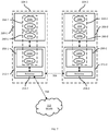
- FIG. 7 is a block diagram of certain internal components of paired client devices in accordance with another embodiment.
- Additional examples disclosed herein are directed to a method for monitoring wireless communications in a client device having a wireless communications interface, comprising: at an operational controller of the client device coupled to the wireless communications interface, controlling the wireless communications interface to establish a wireless connection with an access point according to a set of connection parameters including a channel identifier; transmitting the set of connection parameters from the operational controller to a monitoring controller coupled to an analyzer; at the monitoring controller, responsive to receiving the connection parameters from the operational controller, monitoring a channel corresponding to the channel identifier to obtain a plurality of frames transmitted over the channel; and providing the plurality of frames from the monitoring controller to the analyzer.
- FIG. 1 depicts a wireless communications system 100 , including a plurality of wireless client devices 104 , of which three example devices 104 - 1 , 104 - 2 and 104 - 3 are shown (collectively referred to as client devices 104 , and generically referred to as a client device 104 ; this nomenclature may also be used elsewhere herein).
- the system 100 can include fewer client devices (e.g., two client devices 104 ), or a greater number of client devices than the three devices 104 illustrated in FIG. 1 .
- Each client device 104 is a wireless computing device, and may be mobile (e.g., portable) or stationary (e.g. fixed to a support surface). Accordingly, each client device 104 includes any of a smart phone, a laptop computer, a desktop computer, a tablet computer, a handheld data capture device such as a barcode scanner, and the like.
- the client devices 104 as will be discussed in greater detail, below, each include communication interfaces enabling the devices 104 to establish communication sessions with other computing devices.
- Such communication sessions can be established, for example, between a client device 104 and an access point 108 (e.g. a wireless router) of a wireless local-area network (WLAN) 112 , such as a Wi-Fi network operating according to a suitable one of the IEEE 802.11 family of wireless protocols.
- the WLAN 112 is implemented by four access points 108 - 1 , 108 - 2 , 108 - 3 and 108 - 4 .
- additional WLANs may also be implemented in the system 100 , and the WLAN 112 may be implemented by fewer access points 108 than illustrated, or by a greater number of access points 108 than illustrated.
- the access points 108 are components of one or more wide-area networks (e.g. a cellular network) rather than of the WLAN 112 .
- the WLAN 112 may also be connected to such a wide area network (not shown).
- Each of the devices 104 is enabled to establish a connection with an access point 108 of the WLAN 112 , for example to communicate with other computing devices connected to the WLAN (including, but not limited to, the other devices 104 ).
- the above-mentioned connections may suffer from reduced quality (e.g. reduced connection range, reduced connection bandwidth and the like) for any of a wide variety of reasons.
- Potential sources of reduced connection performance include physical obstructions in the environment in which the system 100 is deployed (e.g. metal shelves in a warehouse), congestion on one or more channels employed by the devices 104 and access points 108 , changes in physical configuration (e.g. shape, orientation and the like) of the devices 104 and access points 108 , operational errors at the devices 104 and access points 108 , and the like.
- the system 100 includes certain components, to be discussed in greater detail below, to enable monitoring of connections established between the devices 104 and the access points 108 to collect data which may be used to detect and/or diagnose performance reductions such as those mentioned above.
- Each of the client devices 104 in the system 100 includes the components shown in FIG. 2A , although the client devices 104 may have heterogeneous form factors and implementations of the components shown.
- the client device 104 includes a central processing unit (CPU), also referred to as a processor 200 , interconnected with a non-transitory computer readable storage medium, such as a memory 204 .
- the memory 204 includes any suitable combination of volatile (e.g. Random Access Memory (RAM)) and non-volatile (e.g. read only memory (ROM), Electrically Erasable Programmable Read Only Memory (EEPROM), flash) memory.
- RAM Random Access Memory
- ROM read only memory
- EEPROM Electrically Erasable Programmable Read Only Memory
- flash flash memory.
- the processor 200 and the memory 204 each comprise one or more integrated circuits (ICs).
- the device 104 also includes at least one input device, and at least one output device, illustrated in FIG. 2A as an input/output device 208 interconnected with the processor 200 .
- the input device includes any suitable one, or any suitable combination of, a touch screen, a keypad, a trigger (e.g. to initiate the performance of any encoding task), a keyboard, a mouse, and the like.
- the output device includes any suitable one, or any suitable combination of a display (e.g., integrated with the above-mentioned touch screen), a speaker, and the like.
- the input/output device 208 is configured to receive input and provide data representative of the received input to the processor 200 , and to receive output from the processor 200 and present the output, e.g. via the emission of sound from the speaker, the rendering of visual indications on the display, and the like.
- the client device 104 also includes a communications interface 212 , enabling the client device 104 to exchange data with other computing devices, including the access points 108 , as well as other client devices 104 (e.g. via direct connections bypassing the WLAN 112 ).
- the communications interface 212 includes a suitable combination of transceiver hardware, such as antenna elements or arrays of antenna elements, analog and digital processing circuitry (e.g. one or more of a radio processor and a digital baseband processor), and the like.
- the communications interface 212 may, for example, be implemented as a system-on-a-chip (SoC) within the device 104 .
- SoC system-on-a-chip
- SoC can include one or more processors and associated memory distinct from the processor 200 and memory 204 mentioned above.
- the components of the client device 104 are interconnected by communication buses (not shown), and powered by a battery or other power source, over the above-mentioned communication buses or by distinct power buses (not shown).
- the memory 204 of the client device 104 stores a plurality of applications, each including a plurality of computer readable instructions executable by the processor 200 .
- the execution of the above-mentioned instructions by the processor 200 causes the client device 104 to implement certain functionality, as discussed herein.
- the applications are therefore said to be configured to perform the functionality in the discussion below.
- the memory 204 of the device 104 stores an operational communications control application 216 , also referred to herein as the application 216 .
- the client device 104 is configured, via execution of the application 216 by the processor 200 , to control the communications interface 212 to establish wireless connections with other devices (e.g. the access points 108 ) and to exchange data over such connections.
- the memory 204 also stores a monitoring communications control application 220 .
- the application 220 is configured to monitor the connections established by the application 216 , for example by capturing some or all of the data exchanged over such connections.
- the application 220 is configured to pass the captured data to an analyzer application 224 stored in the memory 204 for execution by the processor 200 .
- the application 224 is configured to process the captured data to detect and/or diagnose performance reductions in the connections, generate alerts, and the like.
- the applications 216 and 220 implement functionality enabling the application 220 to obtain connection parameters from the application 216 and thereby monitor connections over which the device 104 exchanges data.
- the applications 216 and 220 implement distinct logical entities enabled to access communication channels via the communications interface 212 .
- the applications 216 and 220 each implement distinct media access control (MAC) layers in connection with the communications interface 212 , as well as distinct application layers configured to interact with the above-mentioned MAC layers.
- MAC media access control
- the two distinct MAC layers are addressable via the same MAC address enabling communication with other computing devices via the communications interface 212 .
- the application 216 is configured to establish connections with other computing devices to exchange data with such devices.
- the application 220 is configured as a listener (which may also be referred to as a sniffer) to monitor the above-mentioned connections, without communicating over them.
- FIG. 2B illustrates one such example deployment.
- the applications 216 and 220 can be divided into first application components 216 a and 220 a (e.g. device driver software) executed by the processor 200 (e.g. having been loaded into the processor 200 from the memory 204 , not shown in FIG. 2B ), and second application components 216 b and 220 b (e.g. firmware) executed by a controller 250 of the communications interface 212 (e.g. a controller of the above-mentioned SoC).
- the controller 250 may also execute a transceiver application 254 configured to directly control an antenna component 258 of the communications interface 212 .
- the second components 216 b and 220 b may, for example, be configured to obtain incoming signals and provide outgoing signals to the application 254 .
- the application 254 implements a PHY layer
- each pair of applications 216 a / 216 b and 220 a / 220 b implements a distinct MAC layer. That is, the applications 216 a and 216 b implement a first MAC layer 260 - 1 , while the applications 220 a and 220 b implement a second MAC layer 260 - 2 .
- the first MAC layer 260 - 1 is also referred to as the operational MAC layer, as the device 104 employs the first MAC layer 260 - 1 to communicate with other computing devices.
- the second MAC layer 260 - 2 meanwhile, is also referred to as the monitoring MAC layer and is used to collect of data exchanged with such other devices via the first MAC layer 260 - 1 for analysis.
- the applications 216 and 220 also each include a third component 216 c , 220 c . Further, the application 216 includes a fourth component 216 d .
- the components 216 c and 216 d together define an application layer 264 - 1 associated with the MAC layer 260 - 1
- the component 220 c together with the analyzer application 224 , define an application layer 264 - 2 associated with the MAC layer 260 - 2
- the component 216 d of the application 216 is a control component configured to place the MAC layer 260 - 1 in a connected mode, permitting the MAC layer 260 - 1 to establish connections with other devices via the communications interface 212 (i.e.
- the components 216 c and 220 c are synchronization components configured to exchange configuration data, as will be described below in greater detail, permitting the application 220 to collect data for analysis by the analyzer application 224 according to operational parameters of the operational MAC layer 260 - 1 .
- the applications 216 and 220 may be implemented in the MAC layers 260 rather than the application layers 264 in other embodiments.
- the processor 200 or the controller 250 can be implemented as one or more specifically-configured hardware elements, such as field-programmable gate arrays (FPGAs) and/or application-specific integrated circuits (ASICs).
- FPGAs field-programmable gate arrays
- ASICs application-specific integrated circuits
- the application 216 will be referred to as an operational communications controller 216 , or simply as an operational controller 216 .
- the operational controller 216 in other words, represents a suitable combination of hardware components and software executed by such hardware components for implementing the operational MAC layer 260 - 1 .
- the application 220 will be referred to as a monitoring communications controller 220 , or simply as a monitoring controller 220 .
- FIG. 3 depicts a method 300 of monitoring wireless communications.
- the method 300 will be described in conjunction with its performance in the system 100 , and in particular by the operational controller 216 and the monitoring controller 220 for monitoring the wireless communications of a device 104 (e.g. the device 104 - 1 , although it will be understood that the method 300 may be performed with respect to any device 104 in the system 100 ).
- a device 104 e.g. the device 104 - 1 , although it will be understood that the method 300 may be performed with respect to any device 104 in the system 100 ).
- connection parameters include a channel identifier indicating which of a plurality of available channels (e.g. those defined according to a suitable one of the 802.11 family of protocols) is employed for the connection.
- the connection parameters can also include an identifier of the WLAN 112 , such as a service set identifier (SSID), and an identifier of the specific access point 108 with which the connection was established, such as a basic service set identifier (BSSID, typically a MAC address) corresponding to the access point 108 .
- the connection parameters can also include one or more encryption keys established for the connection, such as a pairwise transient key (PTK), a group temporal key (GTK) or the like.
- connection parameters from the operational controller 216 to the monitoring controller 220 can be accomplished via any suitable communications mechanism, such as via one or more inter-integrated circuit (I2C) interface within the device 104 , an inter-process mechanism provided by an operating system of the device 104 , and the like.
- the connection parameters from the operational controller 216 to the monitoring controller 220 can be contained in a message containing an indicator that the message relates to a newly established connection (e.g. “Start” or the like).
- the monitoring controller 220 is configured to set a current channel for monitoring.
- the monitoring controller 220 can be, for example, configured to instruct the communications interface 212 to pass any frames received on the current channel to the monitoring controller 220 .
- FIG. 4 the system 100 is shown following establishment of a connection 400 between the device 104 - 1 and the access point 108 - 1 at block 305 , and the transmission of connection parameters from the operational controller 216 to the monitoring controller 220 .
- the connection 400 is established using the channel identified as “Ch 36 ”.
- the operational controller 216 therefore interacts with the communications interface 212 to send data over the connection 400 , and to receive any transmissions detected by the communications interface 212 on the channel Ch 36 .
- the monitoring controller 220 also interacts with the communications interface 212 to receive any transmissions detected by the communications interface 212 on the channel Ch 36 .
- the PHY components of the communications interface 212 can be configured, having detected and digitized a signal on the channel Ch 36 , to send the digitized signal to both the controllers 216 and 220 .
- the operational controller 216 is configured to control the communications interface 212 to communicate over the connection corresponding to the parameters sent at block 305 (e.g. the connection 400 in the present embodiment).
- the operational controller 216 is configured, during the performance of block 315 , to receive frames of data detected by the communications interface 212 on the current channel, whether or not such frames are addressed to the operational controller 216 .
- the operational controller 216 is configured to discard any frames that are not addressed to the operational controller 216 (e.g. that do not contain the MAC address of the operational controller 216 ), and to process frames that are addressed to the operational controller 216 . Processing of frames that are addressed to the operational controller 216 is not discussed in detail herein, but can include passing the frames to other components of the device 104 , for example for application-layer processing.
- the monitoring controller 220 is configured, simultaneously with the performance of block 315 by the operational controller 216 , to monitor the channel set at block 310 . More specifically, the monitoring controller 220 is configured to receive any frames detected by the communications interface 212 on the current channel, and to pass all such frames to the analyzer 224 . Prior to passing a frame to the analyzer 224 , the monitoring controller 220 can be configured to decrypt the frame using the encryption key(s) received at block 310 .
- FIG. 5A an illustration of blocks 315 and 320 is shown in the device 104 - 1 following establishment of the connection 400 as shown in FIG. 4 .
- the communications interface 212 has detected a first frame 500 addressed to the operational controller 216 , and a second frame 504 addressed to a separate operational controller (e.g. corresponding to a different device 104 ).
- the controllers 216 and 220 both receive the frames 500 and 504 from the communications interface 212 .
- the operational controller 216 is configured to discard the frame 504 , as the frame 504 is not addressed to the controller 216 .
- the frame 500 is retained for further processing.
- the monitoring controller 220 having received the frames 500 and 504 , passes both frames 500 and 504 (e.g. after decryption and any other suitable MAC-layer processing) to the analyzer 224 . As will now be apparent, neither of the frames 500 and 504 is addressed to the monitoring controller 220 .
- the monitoring controller 220 in other words, is configured to operate in “promiscuous mode”.
- the monitoring controller 220 is configured to receive substantially all data that is received by the operational controller, and to provide all received data to the analyzer 224 for one or more of storage in the memory 204 , analysis, alert generation, or the like.
- the operational controller 216 is configured to determine whether to initiate a roaming scan. As will be apparent to those skilled in the art, a roaming scan can be initiated in response to a variety of trigger conditions being satisfied. For example, if a received signal strength indicator (RSSI) corresponding to the access point 108 to which the device 104 is currently connected drops below a predefined threshold, the determination at block 325 may be affirmative.
- RSSI received signal strength indicator
- the operational controller 216 When the determination at block 325 is negative, the operational controller 216 returns to block 315 , and the performance of block 315 (as well as the performance of block 320 at the monitoring controller 220 ) continues.
- the operational controller 216 is configured to initiate a roaming scan according to a suitable scanning technique, as will be understood by those skilled in the art.
- the roaming scan may include cycling through a plurality of channels to detect available access points 108 operating on such channels, for example via receipt of probe response messages, beacon messages and the like from the access points 108 .
- the operational controller 216 obtains, as a result of the roaming scan, access point data corresponding to each detected access point.
- the access point data for each access point can include an access point identifier, an RSSI value, one or more channel identifiers indicating the channel(s) available for connection with the access point, and the like.
- the operational controller 216 is configured to send the access point data obtained through the roaming scan to the monitoring controller 220 .
- the operational controller 216 prior to performing the roaming scan, is configured to send a notification to the monitoring controller that a roaming scan is to be performed.
- the roaming scan may involve cycling through a number of channel to collect the access point data.
- the monitoring controller 220 meanwhile, continues to monitor the current channel set at block 310 .
- the monitoring controller 220 therefore has not obtained at least a portion of the access point data.
- the monitoring controller 220 is configured, at block 335 , to determine whether scan results (i.e. the above-mentioned access point data) have been received from the operational controller 216 . When the determination is affirmative, the monitoring controller 220 is configured at block 340 to merge the scan results with the monitored data obtained through the performance of block 320 , and then proceed to block 345 . When the determination is negative, the monitoring controller 220 is configured to proceed directly to block 345 .
- the operational controller 216 has obtained access point data 508 corresponding to a plurality of access points 108 .
- the access point data 508 may include data obtained on the same channel as employed for the connection 400 , and data obtained on other channels.
- the operational controller 216 is configured to pass the access point data 508 to the monitoring controller 220 , which is in turn configured to pass the access point data 508 to the analyzer 224 .
- the monitoring controller 220 may have obtained a portion of the access point data, through monitoring of the current channel.
- the monitoring controller 220 can therefore be configured, at block 340 , to merge any partial access point data so obtained with the access point data 508 .
- the monitoring controller 220 can be configured to delete the partial access point data and employ only the data received from the operational controller 216 .
- the operational controller 216 can be configured to omit any access point data received on the channel corresponding to the active connection (e.g. the connection 400 ) from the transmission at block 330 , and the monitoring controller 220 is configured to merge the partial data received from the operational controller 216 with partial data received at the monitoring controller 220 to recreate the access point data 508 .
- the operational controller 216 is configured to determine whether to initiate a handoff procedure, to migrate the connection established prior to block 305 (e.g. the connection 400 with the access point 108 - 1 ) to another access point 108 .
- the determination at block 350 can be made based on the access point data obtained following an affirmative determination at block 325 .
- the operational controller 216 is configured to initiate the handoff according to a suitable handoff mechanism (not discussed in detail herein), and to obtain new connection parameters at block 355 .
- the new connection parameters include the channel identifier, access point identifier, encryption keys and the like for the migrated connection.
- the device 104 - 1 is illustrated after the performance of block 355 . Specifically, the connection 400 has been replaced with a connection 600 with the access point 108 - 4 , on the channel “Ch 40 ”.
- the operational controller 216 is configured to set the new connection parameters as current connection parameters, and to return to block 305 .
- the new connection parameters are provided to the monitoring controller 220 , which therefore updates the monitored channel.
- the monitoring controller 220 is configured to determine whether updated connection parameters have been received. When the determination at block 345 is negative, the monitoring controller 220 returns to block 320 to continue monitoring the current channel. When the determination at block 345 is affirmative, the monitoring controller 220 returns instead to block 310 to set the current channel for monitoring to the newly received channel identifier.
- FIG. 6 illustrates the result of another performance of block 305 following establishment of the connection 600 (as well as another performance of block 310 by the monitoring controller 220 ).
- both the controllers 216 and 220 are configured to receive any frames detected by the communications interface 212 on the same channel (Ch 40 in the present example).
- the performance of the method 300 can continue as described above until the operational controller 216 receives a command (e.g. from the operating system of the device 104 - 1 or the like) to disconnect from the WLAN 112 .
- a command e.g. from the operating system of the device 104 - 1 or the like
- the operational controller 216 is configured to transmit the disconnect command to the monitoring controller 220 prior to tearing down the current connection.
- the monitoring controller 220 is configured to cease monitoring at block 320 .
- the controllers 216 and 220 are implemented on distinct client devices 104 .
- each device 104 in the system 100 can be paired with a monitoring device.
- the client devices 104 implement the operational controller 216 but the monitoring controller 220 is implemented by the paired devices.
- Inter-controller communications can be conducted via any suitable inter-device communications technology, such as Wi-Fi, BluetoothTM, a cabled connection (e.g. USB) and the like. The above-mentioned embodiment is illustrated in FIG.
- the device 104 - 2 is paired with the device 104 - 1 and thus acts as a monitoring device for the device 104 - 1 .
- the device 104 - 1 executes the application components 216 a and 216 b in the processor 200 - 1 and the controller 250 - 1 of the interface 212 - 1 , respectively.
- the controller 250 - 1 also executes the transceiver application 254 - 1 .
- the device 104 - 1 therefore implements the first, or operational, MAC layer 260 - 1 and the associated application layer 264 - 1 enabling communication with the WLAN 112 via the antenna 258 - 1 over a link 700 .
- the second, or monitoring, MAC layer 260 - 2 , and the associated application layer 264 - 2 are implemented by the paired device 104 - 2 rather than the device 104 - 1 . That is, the device 104 - 2 executes the application components 220 a and 220 b in the processor 200 - 2 and the controller 250 - 2 of the interface 212 - 1 , respectively. The controller 250 - 2 also executes the transceiver application 254 - 2 . In the present example, the MAC layers 260 - 1 and 260 - 2 have distinct MAC addresses.
- the device 104 - 2 collects, via the antenna 258 - 2 and the application components 220 a and 220 b , transmissions on the same channel as the link 700 .
- Such transmissions include both those on the link 700 itself and on other links (e.g. between the WLAN 112 and other devices 104 ).
- the control data exchanged by the applications 216 and 220 e.g. at blocks 305 and 310 , as well as blocks 330 and 340
- a link 704 e.g. a BluetoothTM link
- the implementation of operational and monitoring controllers e.g. via the structures shown in FIG. 2B and FIG. 7 , or via other suitable deployments of the functional components noted above
- the monitoring controller may more effectively collect data relevant to the performance of the operational controller (e.g. on the same wireless channel), while mitigating or eliminating performance impacts on the operational controller.
- the implementation of the monitoring controller in a paired device, or in the same device as the operational controller may increase the likelihood of the data collected by the monitoring controller accurately reflecting a perspective of the operational controller (e.g. imposed by the housing of the devices, the position of the devices within the facility, and the like).
- a includes . . . a”, “contains . . . a” does not, without more constraints, preclude the existence of additional identical elements in the process, method, article, or apparatus that comprises, has, includes, contains the element.
- the terms “a” and “an” are defined as one or more unless explicitly stated otherwise herein.
- the terms “substantially”, “essentially”, “approximately”, “about” or any other version thereof, are defined as being close to as understood by one of ordinary skill in the art, and in one non-limiting embodiment the term is defined to be within 10%, in another embodiment within 5%, in another embodiment within 1% and in another embodiment within 0.5%.
- the term “coupled” as used herein is defined as connected, although not necessarily directly and not necessarily mechanically.
- a device or structure that is “configured” in a certain way is configured in at least that way, but may also be configured in ways that are not listed.
- processors such as microprocessors, digital signal processors, customized processors and field programmable gate arrays (FPGAs) and unique stored program instructions (including both software and firmware) that control the one or more processors to implement, in conjunction with certain non-processor circuits, some, most, or all of the functions of the method and/or apparatus described herein.
- processors or “processing devices” such as microprocessors, digital signal processors, customized processors and field programmable gate arrays (FPGAs) and unique stored program instructions (including both software and firmware) that control the one or more processors to implement, in conjunction with certain non-processor circuits, some, most, or all of the functions of the method and/or apparatus described herein.
- FPGAs field programmable gate arrays
- unique stored program instructions including both software and firmware
- an embodiment can be implemented as a computer-readable storage medium having computer readable code stored thereon for programming a computer (e.g., comprising a processor) to perform a method as described and claimed herein.
- Examples of such computer-readable storage mediums include, but are not limited to, a hard disk, a CD-ROM, an optical storage device, a magnetic storage device, a ROM (Read Only Memory), a PROM (Programmable Read Only Memory), an EPROM (Erasable Programmable Read Only Memory), an EEPROM (Electrically Erasable Programmable Read Only Memory) and a Flash memory.
Landscapes
- Engineering & Computer Science (AREA)
- Computer Networks & Wireless Communication (AREA)
- Signal Processing (AREA)
- Mobile Radio Communication Systems (AREA)
Abstract
Description
Claims (19)
Priority Applications (4)
| Application Number | Priority Date | Filing Date | Title |
|---|---|---|---|
| US16/044,725 US10652933B2 (en) | 2018-07-25 | 2018-07-25 | System, method and apparatus for monitoring wireless communications |
| PCT/US2019/039394 WO2020023176A1 (en) | 2018-07-25 | 2019-06-27 | System, method and apparatus for monitoring wireless communications |
| GB2100825.5A GB2590255B (en) | 2018-07-25 | 2019-06-27 | System, method and apparatus for monitoring wireless communications |
| DE112019003732.3T DE112019003732T5 (en) | 2018-07-25 | 2019-06-27 | SYSTEM, METHOD AND DEVICE FOR MONITORING WIRELESS COMMUNICATIONS |
Applications Claiming Priority (1)
| Application Number | Priority Date | Filing Date | Title |
|---|---|---|---|
| US16/044,725 US10652933B2 (en) | 2018-07-25 | 2018-07-25 | System, method and apparatus for monitoring wireless communications |
Publications (2)
| Publication Number | Publication Date |
|---|---|
| US20200037372A1 US20200037372A1 (en) | 2020-01-30 |
| US10652933B2 true US10652933B2 (en) | 2020-05-12 |
Family
ID=69177282
Family Applications (1)
| Application Number | Title | Priority Date | Filing Date |
|---|---|---|---|
| US16/044,725 Active US10652933B2 (en) | 2018-07-25 | 2018-07-25 | System, method and apparatus for monitoring wireless communications |
Country Status (4)
| Country | Link |
|---|---|
| US (1) | US10652933B2 (en) |
| DE (1) | DE112019003732T5 (en) |
| GB (1) | GB2590255B (en) |
| WO (1) | WO2020023176A1 (en) |
Families Citing this family (5)
| Publication number | Priority date | Publication date | Assignee | Title |
|---|---|---|---|---|
| US11785569B2 (en) * | 2019-03-27 | 2023-10-10 | Mediatek Singapore Pte. Ltd. | Device and method for enrolling a wireless access point into a map wireless network |
| US11696129B2 (en) * | 2019-09-13 | 2023-07-04 | Samsung Electronics Co., Ltd. | Systems, methods, and devices for association and authentication for multi access point coordination |
| CN114051260B (en) * | 2021-11-16 | 2023-09-26 | 中电科思仪科技股份有限公司 | Signal simulation method and device for wireless connection aggregation MAC layer protocol data unit |
| US12021688B2 (en) * | 2022-08-10 | 2024-06-25 | Zebra Technologies Corporation | Dynamic network configuration for printers |
| US20260006580A1 (en) * | 2024-06-28 | 2026-01-01 | Zebra Technologies Corporation | Method and System for Roaming Based on Range Differentials |
Citations (6)
| Publication number | Priority date | Publication date | Assignee | Title |
|---|---|---|---|---|
| US20070076664A1 (en) * | 2005-09-30 | 2007-04-05 | Yafan An | Handoff decision making for heterogeneous network environments |
| US20070207770A1 (en) * | 2004-06-18 | 2007-09-06 | Jorma Ikaheimo | Method, Apparatus And Computer Program Product For Monitoring Data Transmission Connections |
| US20100246416A1 (en) * | 2009-03-25 | 2010-09-30 | Amit Sinha | Systems and methods for remote testing of wireless lan access points |
| US20130142050A1 (en) * | 2011-12-06 | 2013-06-06 | Seven Networks, Inc. | Cellular or wifi mobile traffic optimization based on public or private network destination |
| US20140029603A1 (en) * | 2011-03-29 | 2014-01-30 | Fujitsu Limited | Method and device for time-synchronization in ad hoc network |
| US9078153B1 (en) * | 2014-10-31 | 2015-07-07 | Quantenna Communications, Inc. | Wireless local area network with spatial diagnostics |
-
2018
- 2018-07-25 US US16/044,725 patent/US10652933B2/en active Active
-
2019
- 2019-06-27 WO PCT/US2019/039394 patent/WO2020023176A1/en not_active Ceased
- 2019-06-27 DE DE112019003732.3T patent/DE112019003732T5/en active Pending
- 2019-06-27 GB GB2100825.5A patent/GB2590255B/en active Active
Patent Citations (6)
| Publication number | Priority date | Publication date | Assignee | Title |
|---|---|---|---|---|
| US20070207770A1 (en) * | 2004-06-18 | 2007-09-06 | Jorma Ikaheimo | Method, Apparatus And Computer Program Product For Monitoring Data Transmission Connections |
| US20070076664A1 (en) * | 2005-09-30 | 2007-04-05 | Yafan An | Handoff decision making for heterogeneous network environments |
| US20100246416A1 (en) * | 2009-03-25 | 2010-09-30 | Amit Sinha | Systems and methods for remote testing of wireless lan access points |
| US20140029603A1 (en) * | 2011-03-29 | 2014-01-30 | Fujitsu Limited | Method and device for time-synchronization in ad hoc network |
| US20130142050A1 (en) * | 2011-12-06 | 2013-06-06 | Seven Networks, Inc. | Cellular or wifi mobile traffic optimization based on public or private network destination |
| US9078153B1 (en) * | 2014-10-31 | 2015-07-07 | Quantenna Communications, Inc. | Wireless local area network with spatial diagnostics |
Also Published As
| Publication number | Publication date |
|---|---|
| GB2590255A (en) | 2021-06-23 |
| US20200037372A1 (en) | 2020-01-30 |
| GB2590255B (en) | 2022-11-23 |
| GB202100825D0 (en) | 2021-03-10 |
| DE112019003732T5 (en) | 2021-04-08 |
| WO2020023176A1 (en) | 2020-01-30 |
Similar Documents
| Publication | Publication Date | Title |
|---|---|---|
| US10652933B2 (en) | System, method and apparatus for monitoring wireless communications | |
| US10148672B2 (en) | Detection of rogue access point | |
| US20200221378A1 (en) | Active Scanning Enhancements for Multi-Band and Multi-Basic Service Set Discovery | |
| JP6834058B2 (en) | WI-FI hotspot connection method and terminal | |
| US20140146727A1 (en) | Systems and methods for service discovery | |
| US12016064B2 (en) | Method for establishing hotspot connection and terminal device | |
| JP2020504573A (en) | Cell switching method and apparatus | |
| CN107846723B (en) | Wireless local area network scanning method and device, computer equipment and storage medium | |
| US9774990B2 (en) | Proximity-based verification of programming instructions | |
| WO2014164385A1 (en) | Method and apparatus for performing scan operations | |
| CN107820303B (en) | Mobile terminal wireless local area network scanning method and device and computer equipment | |
| CN110545549B (en) | Cell measurement method, measurement configuration method, terminal and network equipment | |
| CN106961710B (en) | A kind of network access method and terminal | |
| US10009816B2 (en) | Communication apparatus, method of controlling the same, and communication system | |
| CN110677842A (en) | Network searching method, device, terminal equipment and storage medium | |
| WO2024184726A1 (en) | Calibrated a-iot ranging | |
| CN113453293B (en) | Service receiving method and device, communication device | |
| CN201937832U (en) | Detecting device for WIFI (wireless fidelity) connection status | |
| WO2015068472A1 (en) | Terminal device, information processing device, and information provision device | |
| US20220248322A1 (en) | Cell selection method and apparatus, communication device, and storage medium | |
| EP4277333A1 (en) | Beam scanning method and apparatus, communication device, and storage medium | |
| KR20120126860A (en) | mobile communication system switching and searching an optimal WiFi path using a dual WiFi chip and controlling method therefor | |
| US10448277B2 (en) | Method, system and apparatus for multicast data rate selection | |
| WO2016027545A1 (en) | Wireless communication device and wireless communication method | |
| US20240267867A1 (en) | Network identification collision detection for private networks |
Legal Events
| Date | Code | Title | Description |
|---|---|---|---|
| AS | Assignment |
Owner name: ZIH CORP., ILLINOIS Free format text: ASSIGNMENT OF ASSIGNORS INTEREST;ASSIGNORS:RAJENDIRAN, SUBRAMANI;SHATIL, OHAD;SHIVARUDRAPPA, SATISH;AND OTHERS;SIGNING DATES FROM 20180724 TO 20180725;REEL/FRAME:046454/0534 |
|
| FEPP | Fee payment procedure |
Free format text: ENTITY STATUS SET TO UNDISCOUNTED (ORIGINAL EVENT CODE: BIG.); ENTITY STATUS OF PATENT OWNER: LARGE ENTITY |
|
| AS | Assignment |
Owner name: ZEBRA TECHNOLOGIES CORPORATION, ILLINOIS Free format text: MERGER;ASSIGNOR:ZIH CORP.;REEL/FRAME:048470/0848 Effective date: 20181220 |
|
| AS | Assignment |
Owner name: JPMORGAN CHASE BANK, N.A., AS COLLATERAL AGENT, NEW YORK Free format text: SECURITY INTEREST;ASSIGNOR:ZEBRA TECHNOLOGIES CORPORATION;REEL/FRAME:049674/0916 Effective date: 20190701 |
|
| STPP | Information on status: patent application and granting procedure in general |
Free format text: NOTICE OF ALLOWANCE MAILED -- APPLICATION RECEIVED IN OFFICE OF PUBLICATIONS |
|
| STCF | Information on status: patent grant |
Free format text: PATENTED CASE |
|
| AS | Assignment |
Owner name: JPMORGAN CHASE BANK, N.A., NEW YORK Free format text: SECURITY INTEREST;ASSIGNORS:ZEBRA TECHNOLOGIES CORPORATION;LASER BAND, LLC;TEMPTIME CORPORATION;REEL/FRAME:053841/0212 Effective date: 20200901 |
|
| AS | Assignment |
Owner name: LASER BAND, LLC, ILLINOIS Free format text: RELEASE OF SECURITY INTEREST - 364 - DAY;ASSIGNOR:JPMORGAN CHASE BANK, N.A.;REEL/FRAME:056036/0590 Effective date: 20210225 Owner name: ZEBRA TECHNOLOGIES CORPORATION, ILLINOIS Free format text: RELEASE OF SECURITY INTEREST - 364 - DAY;ASSIGNOR:JPMORGAN CHASE BANK, N.A.;REEL/FRAME:056036/0590 Effective date: 20210225 Owner name: TEMPTIME CORPORATION, NEW JERSEY Free format text: RELEASE OF SECURITY INTEREST - 364 - DAY;ASSIGNOR:JPMORGAN CHASE BANK, N.A.;REEL/FRAME:056036/0590 Effective date: 20210225 |
|
| MAFP | Maintenance fee payment |
Free format text: PAYMENT OF MAINTENANCE FEE, 4TH YEAR, LARGE ENTITY (ORIGINAL EVENT CODE: M1551); ENTITY STATUS OF PATENT OWNER: LARGE ENTITY Year of fee payment: 4 |