US10651656B2 - UDE-based robust droop control for parallel inverter operation - Google Patents
UDE-based robust droop control for parallel inverter operation Download PDFInfo
- Publication number
- US10651656B2 US10651656B2 US15/698,956 US201715698956A US10651656B2 US 10651656 B2 US10651656 B2 US 10651656B2 US 201715698956 A US201715698956 A US 201715698956A US 10651656 B2 US10651656 B2 US 10651656B2
- Authority
- US
- United States
- Prior art keywords
- ude
- control
- reactive power
- voltage
- uncertainty
- Prior art date
- Legal status (The legal status is an assumption and is not a legal conclusion. Google has not performed a legal analysis and makes no representation as to the accuracy of the status listed.)
- Active, expires
Links
Images


Classifications
-
- H—ELECTRICITY
- H02—GENERATION; CONVERSION OR DISTRIBUTION OF ELECTRIC POWER
- H02J—ELECTRIC POWER NETWORKS; CIRCUIT ARRANGEMENTS OR SYSTEMS FOR SUPPLYING OR DISTRIBUTING ELECTRIC POWER; SYSTEMS FOR STORING ELECTRIC ENERGY
- H02J3/00—Circuit arrangements for AC mains or AC distribution networks
- H02J3/38—Arrangements for feeding a single network from two or more generators or sources in parallel; Arrangements for feeding already energised networks from additional generators or sources in parallel
- H02J3/46—Controlling the sharing of generated power between the generators, sources or networks
-
- H—ELECTRICITY
- H02—GENERATION; CONVERSION OR DISTRIBUTION OF ELECTRIC POWER
- H02M—APPARATUS FOR CONVERSION BETWEEN AC AND AC, BETWEEN AC AND DC, OR BETWEEN DC AND DC, AND FOR USE WITH MAINS OR SIMILAR POWER SUPPLY SYSTEMS; CONVERSION OF DC OR AC INPUT POWER INTO SURGE OUTPUT POWER; CONTROL OR REGULATION THEREOF
- H02M7/00—Conversion of AC power input into DC power output; Conversion of DC power input into AC power output
- H02M7/42—Conversion of DC power input into AC power output without possibility of reversal
- H02M7/44—Conversion of DC power input into AC power output without possibility of reversal by static converters
- H02M7/48—Conversion of DC power input into AC power output without possibility of reversal by static converters using discharge tubes with control electrode or semiconductor devices with control electrode
- H02M7/493—Conversion of DC power input into AC power output without possibility of reversal by static converters using discharge tubes with control electrode or semiconductor devices with control electrode the static converters being arranged for operation in parallel
-
- H—ELECTRICITY
- H02—GENERATION; CONVERSION OR DISTRIBUTION OF ELECTRIC POWER
- H02M—APPARATUS FOR CONVERSION BETWEEN AC AND AC, BETWEEN AC AND DC, OR BETWEEN DC AND DC, AND FOR USE WITH MAINS OR SIMILAR POWER SUPPLY SYSTEMS; CONVERSION OF DC OR AC INPUT POWER INTO SURGE OUTPUT POWER; CONTROL OR REGULATION THEREOF
- H02M7/00—Conversion of AC power input into DC power output; Conversion of DC power input into AC power output
- H02M7/42—Conversion of DC power input into AC power output without possibility of reversal
- H02M7/44—Conversion of DC power input into AC power output without possibility of reversal by static converters
- H02M7/48—Conversion of DC power input into AC power output without possibility of reversal by static converters using discharge tubes with control electrode or semiconductor devices with control electrode
- H02M7/53—Conversion of DC power input into AC power output without possibility of reversal by static converters using discharge tubes with control electrode or semiconductor devices with control electrode using devices of a triode or transistor type requiring continuous application of a control signal
- H02M7/537—Conversion of DC power input into AC power output without possibility of reversal by static converters using discharge tubes with control electrode or semiconductor devices with control electrode using devices of a triode or transistor type requiring continuous application of a control signal using semiconductor devices only, e.g. single switched pulse inverters
- H02M7/539—Conversion of DC power input into AC power output without possibility of reversal by static converters using discharge tubes with control electrode or semiconductor devices with control electrode using devices of a triode or transistor type requiring continuous application of a control signal using semiconductor devices only, e.g. single switched pulse inverters with automatic control of output wave form or frequency
- H02M7/5395—Conversion of DC power input into AC power output without possibility of reversal by static converters using discharge tubes with control electrode or semiconductor devices with control electrode using devices of a triode or transistor type requiring continuous application of a control signal using semiconductor devices only, e.g. single switched pulse inverters with automatic control of output wave form or frequency by pulse-width modulation
-
- H—ELECTRICITY
- H02—GENERATION; CONVERSION OR DISTRIBUTION OF ELECTRIC POWER
- H02M—APPARATUS FOR CONVERSION BETWEEN AC AND AC, BETWEEN AC AND DC, OR BETWEEN DC AND DC, AND FOR USE WITH MAINS OR SIMILAR POWER SUPPLY SYSTEMS; CONVERSION OF DC OR AC INPUT POWER INTO SURGE OUTPUT POWER; CONTROL OR REGULATION THEREOF
- H02M1/00—Details of apparatus for conversion
- H02M1/0003—Details of control, feedback or regulation circuits
- H02M1/0025—Arrangements for modifying reference values, feedback values or error values in the control loop of a converter
-
- H02M2001/0025—
Definitions
- Embodiments are related to control devices for parallel operated inverters to achieve accurate proportional load sharing. Embodiments are also related to microgrid, smart grid, and renewable energy applications. Embodiments further relate to UDE (Uncertainty and Disturbance Estimator)-based control methods.
- UDE Uncertainty and Disturbance Estimator
- Droop control is a control strategy commonly applied to power generators to allow load sharing. This strategy allows for equal load balancing between inverters, but requires that output impedances be matched between the inverters. This results in inaccurate reactive power sharing—an important aspect of power sharing performance.
- Traditional droop control strategies are also unable to handle system disturbances, such as large or quick load changes, variations in output impedances, and fluctuating DC-link voltages.
- UDE Uncertainty and Disturbance Estimator
- a control system and method include a control strategy and a UDE (Uncertainty and Disturbance Estimator)-based controller incorporated into the control strategy.
- the UDE-based controller regulates the reactive power against the output generated by a reactive power reference unit according to the load voltage to generate the amplitude of the control voltage.
- the conventional droop method is adopted to regulate the real power for real power sharing, wherein the phase of the control voltage is generated.
- Both the amplitude and the phase of the control voltage form the final control outputs for parallel operated inverters to achieve desired load sharing or power sharing performance.
- FIG. 1 illustrates a schematic diagram of a prior art circuit having two parallel operated inverters with inductive output impedance
- FIG. 2 illustrates a block diagram of a prior art droop control strategy
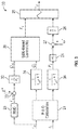
- FIG. 3 illustrates a block diagram depicting a UDE-based robust droop control strategy, in accordance with an example embodiment
- FIG. 4A and FIG. 4B respectively illustrate a pictorial diagram of an experimental setup and its circuit diagram, in accordance with an example embodiment
- FIGS. 5A-5F illustrate a group of graphs depicting nominal experimental results for power sharing performance, in accordance with example embodiments.
- FIGS. 6A-6D illustrate a group of graphs depicting transient experimental results under different scenarios, in accordance with example embodiments.
- terms such as “a,” “an,” or “the,” again, may be understood to convey a singular usage or to convey a plural usage, depending at least in part upon context.
- the term “based on” may be understood as not necessarily intended to convey an exclusive set of factors and may, instead, allow for existence of additional factors not necessarily expressly described, again, depending at least in part on context.
- renewable energies such as wind energy, solar energy, wave and tidal energy
- fuel cell and battery electric vehicles can be treated as renewable energies when they are connected to the grid through the vehicle-to-grid mode.
- power inverters are adopted in these applications, which are also known as distributed generations, to interface with the utility grid or the microgrid.
- the power electronic devices face big challenges with the needs of high current and high power.
- several power inverters are required in parallel operation due to the current limitation or cost limitation of power electronic devices. Another reason for the need of parallel operation of inverters is to provide system redundancy and high reliability from the requirements of critical customers.
- Power sharing based on droop characteristics is widely used in parallel operation of inverters. Also, sharing the load among distributed generations is popular for the operation of islanded microgrid.
- One major advantage of the droop control is that no external communication mechanism is needed among the parallel inverters, which gives significant flexibility without the interdependency of the local controllers for the balance between power generations and the demands.
- Another advantage is that the system inherits the “plug and play” feature without changing the control strategies of parallel units.
- the conventional droop control is not able to achieve accurate reactive power sharing among parallel units due to the mismatched output impedance, and presents poor transient performance. Also system disturbances, e.g., large or fast change of the load, variations of output impedance, and fluctuating DC-link voltage, often affect the load sharing performance.
- the virtual impedance is a widely used approach to improve power sharing performance among parallel operated inverters. Adding a virtual inductor and estimating the effect of the line impedance may improve the sharing performance via changing the droop coefficients.
- the complex virtual impedance can be designed to minimize the fundamental and harmonic circulating currents in the parallel system.
- the communication and adaptive virtual impedance can be combined to enhance the accuracy of reactive power sharing, and the time delay problem in communication may be improved.
- An accurate power sharing can be realized by regulating the virtual impedance at fundamental positive sequence, fundamental negative sequence, and harmonic frequencies.
- the sharing performance of virtual impedance based method will be affected by the variations of the output filter components. With the introduction of virtual impedance, the output voltages of inverters are sensitive to the harmonic currents.
- a number of methods have been proposed for sharing the load. For example, injecting a harmonic voltage according to the output harmonic current may be used for improving the total harmonic current sharing, and power sharing may be achieved as well.
- a small signal injection method has been proposed to improve the accuracy of the reactive power sharing.
- a Q-V dot droop control method has also been proposed to improve the accuracy of reactive power sharing following the idea of changing the droop coefficients.
- a virtual flux droop method has been proposed, which involves drooping the virtual flux instead of the voltage to achieve real power and reactive power sharing with low-frequency deviation.
- the voltage droop strategy has also been redesigned to deal with mismatched output impedance for power sharing.
- the robust droop control introduces an integrator to enhance the robustness of droop control to achieve accurate proportional load sharing.
- hierarchical droop control is another method and trend that attempts to cope with the disadvantages of conventional droop control through communication among parallel operated inverters.
- the primary control is the droop control method, and voltage and frequency deviations are compensated by the secondary control through communication.
- hierarchical droop control also has its own drawbacks, such as the cost of communication, reliability, location, and slow responses.
- the disclosed embodiments thus disclose a new droop control strategy based on a UDE (Uncertainty and Disturbance Estimator) method for parallel operated inverters to achieve accurate proportional load sharing, particularly for reactive power sharing.
- the UDE control algorithm is based on the assumption that the uncertainty and disturbances can be estimated using a filter with the appropriate bandwidth.
- the reactive power dynamics is developed from the equation of power delivering passed through a low-pass filter.
- the load voltage is fed back to generate the reactive power reference for the design of the UDE-based controller, which helps achieve accurate sharing control of reactive power.
- the reactive power sharing can be achieved in the presence of model nonlinearity and uncertainties (e.g., parameter drifts and uncertain output impedance) and system disturbances (e.g., fluctuating DC-link voltage and load change).
- the conventional droop control method is adopted for the frequency regulation, as it can achieve accurate proportional real power sharing.
- the effectiveness of the proposed control method is investigated by theoretical analysis and demonstrated through experimental studies on an experimental test rig, which consists of two parallel operated power inverters from Texas Instruments (TI).
- FIG. 1 illustrates a schematic diagram of a prior art circuit 10 having two parallel operated inverters 12 and 19 with two individual inductive output impedances 14 and 18 to support a common load 16 (i.e., Z).
- a common load 16 i.e., Z
- FIG. 2 illustrates a block diagram of a prior art droop control strategy 20 with a power component 21 for the calculation of P (Real Power) and Q (Reactive Power) labeled in FIG. 2 as “P&Q calculation.”
- the outputs from the P&Q calculation component 21 are fed as inputs to droop coefficient components 22 and 24 (i.e., parameters n i and m i are the droop coefficients, which are related to the capacity of the inverters) for both reactive power and real power channels, respectively.
- Output from the components 22 and 24 are respectively fed to summation components 25 and 27 to form the amplitude and the phase of the control voltage for a sinusoidal control output component 28 , wherein the phase of the control voltage is generated by summation components 27 passing through an integral component 26 .
- the parameters n i and m i are the droop coefficients, which are related to the capacity of the inverters, and usually defined by the requirement of customers.
- the block diagram of this conventional droop control is shown in FIG. 2 .
- the disclosed embodiments generally include two distinct parts: the reactive power regulation for reactive power sharing, and the real power regulation for real power sharing.
- the reactive power dynamics is generated through the reactive power passing by a low-pass filter
- the reactive power reference is generated by the drop of load voltage
- the incorporation of a uncertainty and disturbance estimator (UDE) achieves reactive power regulation.
- UDE uncertainty and disturbance estimator
- the real power sharing conventional droop control method is adopted by adding a low-pass filter.
- both disclosed low-pass filters can be the first-order low-pass filters. The additional purpose of such filters is to reduce high-frequency noise frequencies that occur during the switching of harmonics and sampling disturbances.
- the UDE integration of reactive power control involves three parts: the generation of the reactive power dynamics from the low-pass filter, the reactive power regulation with UDE-based control, and the generation of the reactive power reference from load voltage droop.
- FIG. 3 illustrates a block diagram of a UDE-based robust droop control strategy 30 , in accordance with an example embodiment.
- the UDE-based robust droop control strategy 30 includes two control channels.
- the reactive power Q i is calculated from a P&Q calculation component 21 passing by a low-pass filter G qi (s) 34
- the reactive power reference Q ri is generated from feedback load voltage v o passing by an RMS (Root Mean Square) component 23 that calculates an RMS voltage
- RMS Root Mean Square
- n i component 32 Central to the reactive power regulation channel is the implementation of a UDE-based controller 38 that is based on a mathematical controls engineering model as discussed herein in further detail with respect to equation (16).
- the real power P i is calculated from the same P&Q calculation component 21 passing by a low-pass filter G pi (s) 36 .
- the real power is regulated with a droop coefficient m i component 24 , a summation component 27 , and an integral component 26 .
- the amplitude and the phase of the control voltage to form a sinusoidal control output component 28 are outputs from the components 38 and 26 , respectively.
- FIG. 3 thus illustrates a block diagram depicting a control strategy 30 offering a UDE-based robust droop control algorithm, in accordance with an example embodiment.
- the disclosed embodiments offer a new droop control strategy based on a UDE method for parallel operated inverters.
- the UDE-based method can be adopted to deal with nonlinearity, uncertainty and system disturbances.
- the conventional droop control method can be adopted with the change of adding a low-pass filter.
- the reactive power control is developed for reactive power sharing with the control objective that the output reactive power of parallel operated inverters Q i asymptotically tracks the reactive power reference Q ri as shown in FIG. 3 .
- ⁇ qi Q . i - V o ⁇ qi ⁇ V oi ⁇ E i + V o 2 ⁇ qi ⁇ Z oi + Q i ⁇ qi .
- equation (15) the term ⁇ qi can be estimated according to equation (15) as follows:
- E i ⁇ qi ⁇ Z oi V o ⁇ [ V o 2 ⁇ qi ⁇ Z oi + Q i ⁇ qi + L - 1 ⁇ ⁇ 1 1 - G fi ⁇ ( s ) ⁇ * ( Q . ri + K qi ⁇ e qi ) - L - 1 ⁇ ⁇ sG fi ⁇ ( s ) 1 - G fi ⁇ ( s ) ⁇ * Q i ] . ( 16 )
- the reactive power reference Q ri may be required for reactive power sharing. Instead of drooping the voltage set-point E i , the load voltage V o should be drooped. This idea can be applied to change the voltage droop in equation (5), the reactive power reference is generated as shown in FIG. 3 as indicated by equation (17) below:
- load-voltage feedback can be implemented in some implementations for improving the conventional droop control via directly re-designing the voltage droop strategy.
- the feedback of load voltage can be used to generate the reactive power reference, which is different from these other implementations.
- a PWM modulation unit can be applied in the final controller output v ri shown in FIG. 3 for the control of power electronic devices to convert DC power to AC power, which introduces the disturbances of fluctuating DC-link voltage into the system.
- the variations of the DC-link voltage can also be treated as external disturbances and handled by the UDE-based robust droop control shown in equation (16).
- the DC-link voltage can be measured for other purposes, e.g., protection.
- the UDE-based robust droop control of equation (16) introduces some extra control parameters, error feedback gain in equation (13), and the UDE filter in equation (15), to enhance the transient performance of reactive power sharing for parallel operated inverters.
- an inner-loop current controller can be added into the controller output v ri in FIG. 3 with other purposes, such as harmonic improvement with virtual impedance design and current protection.
- the added virtual impedance will not affect the sharing performance with the proposed embodiments.
- the conventional droop control of equation (6) with a first-order low-pass filter is adopted as it can achieve accurate proportional sharing for real power.
- G pi ⁇ ( s ) 1 ⁇ pi ⁇ s + 1 is applied for the real power calculation with the time constant ⁇ pi , which filters out the high-frequency noises, such as switching harmonics and sampling disturbances.
- FIG. 4A and FIG. 4B respectively illustrate a pictorial diagram of an experimental setup 40 and a schematic diagram of an improved control circuit 50 , in accordance with an example embodiment.
- the capacitor 57 i.e., C L2
- the capacitor 57 is initially bypassed by a switch CB 2 for the test of load change.
- Inverter I labeled in FIG. 4B as inverter 52
- Inverter II labeled in FIG. 4B as inverter 70
- the circuit 50 depicted in FIG. 4B further includes a PWM component 54 connected to the first inverter 54 and a PWM component 68 connected to the second inverter 70 for inverters control respectively.
- the Inverter I 52 has an output impedance (LC filter) with an inductor 55 having parameters L 1 ,R 1 and a capacitor 58 with parameters C 1 .
- the Inverter II 70 has an output impedance (LC filter) with an inductor 66 with parameters L 2 ,R 2 and a capacitor 64 (C 2 ).
- the load voltage V o2 is measured by Inverter II.
- the parameters of the inverters are provided in Table I below.
- the impedance of inverter includes the parasitic resistance.
- the affecting resistance also can be lumped into the uncertain term ⁇ qi of equation (11) and compensated in the controller design.
- the PWM frequency for power electronic devices can be set as, for example, 19.2 kHz for both inverters I and II.
- Both inverters 52 and 70 can be controlled through a TI controlCARD with T1 F28M35H52C1.
- Parameters Values Parameters Values ⁇ q1 , ⁇ q2 0.0005 s K q1 , K q2 50 ⁇ p1 , ⁇ p2 0.0005 s ⁇ 1 , ⁇ 2 0.001 s ⁇ r1 , ⁇ r2 0.0005 s — —
- the UDE filter G fi (s) is chosen as a first-order low-pass filter
- E i V o + Q i ⁇ Z oi V o + ⁇ qi ⁇ Z oi V o ⁇ [ Q . ri + ( K qi + 1 ⁇ i ) ⁇ e qi + K qi ⁇ i ⁇ ⁇ 0 t ⁇ e qi ⁇ dt ] . ( 23 )
- control law set forth in equation (23) above includes a derivative term Q n .
- a low pass filter can be introduced to approximate Q n numerically as
- E i V o + Q i ⁇ Z oi V o + ⁇ qi ⁇ Z oi V o ⁇ [ Q ri - Q ⁇ ri ⁇ ri + ( K qi + 1 ⁇ i ) ⁇ e qi + K qi ⁇ i ⁇ ⁇ 0 t ⁇ e qi ⁇ dt ] . ( 24 )
- the cut-off frequency of the lower filters to approximately Q ri is also chosen as about 318 Hz to cover the spectrum of disturbances and to achieve a fast system response.
- FIGS. 5A-5F illustrate a group of graphs 82 , 84 , 86 , 88 , 89 , and 90 depicting nominal experimental results for power share performance, in accordance with example embodiments.
- Case 1 two cases are discussed below: Case 1 and Case 2.
- the system response curves with the proposed UDE-based robust droop control of equations (16) and (6) are shown in FIGS. 5A-5F .
- the frequency drop is shown in graph 88 of FIG. 5D due to the effect of positive real power as shown in graph 82 of FIG. 5A .
- the voltage drop as shown in graph 89 is high in the single-inverter mode, and the negative drop direction is due to the effect of negative reactive power as shown in graph 84 in FIG. 5B with the capacitive load.
- the switch CB 1 is turned ON, and Inverter II is connected to the load.
- the load voltage V o2 is measured by Inverter II for voltage synchronization with the zero-crossing technique.
- Inverter II is disconnected, the reactive power and voltage, real power and frequency of Inverter I are back to the initial state.
- the corresponding AC voltage is shown in graph 86 of FIG. 5C .
- the steady-state sharing performance is shown in Table III. According to the formulas proposed in, for example, Q.-C. Zhong and T.
- FIGS. 6A-6D illustrate a group of graphs 102 , 104 , 106 , 108 , 110 , 112 , 114 , 116 , 118 , 120 , 122 , and 124 depicting transient experimental results under different scenarios, in accordance with example embodiments.
- the load is connected to the Inverter I only, with switch CB 1 OFF and switch CB 2 ON.
- the reactive power of inverter II has a positive spike correspondingly. Both the reactive powers of two inverters settle down with 2:1 sharing quickly within 0.4 s. The output voltage has small spike and goes back to normal state quickly shown in graphs 122 of FIG. 6D .
- the UDE-based robust droop control can deal with the fluctuating DC-link voltage.
- the disclosed technology differs from other methods in its ability to compensate for uncertainties and system disturbances.
- Other droop control methods can only adjust for variations in inverter output impedances and require external regulators.
- the disclosed technology can adjust not only for varying output impedances, but for drastic load changes and fluctuating DC-link voltages that can occur in practical applications, without requiring external regulatory devices.
- Benefits of the disclosed approach include improved reactive power sharing accuracy between parallel inverters used in power grids, improved transient performance between parallel inverters, improved management of system disturbances, such as drastic load changes, variations of output impedance, and fluctuating DC-link voltage, and additionally, there is no longer a concern about matching output impedances of parallel inverters in power grids.
- a system can be implemented for controlling an inverter to achieve proportional load sharing in parallel operation mode.
- a system can include, for example, one or more sensors or a group of sensors that measure the load voltage and the current associated with the inverter; a power unit that calculates the real power and the reactive power of the inverter; a voltage unit that calculates the RMS load voltage; a reactive power reference unit that generates the reactive power reference; a low-pass filter to filter the high-frequency component of the reactive power; a reactive power regulation unit to control the reactive power and generate the amplitude of the control voltage; a real power regulation unit to generate the phase of the control voltage; and a voltage forming unit to form the control signal according to the said amplitude and said phase of the control voltage.
- the reactive power regulation unit can be implemented as a UDE (Uncertainty and Disturbance Estimator)-based controller.
- a UDE-based controller can include a configuration for error dynamics, a UDE filter, and a control configuration.
- the aforementioned UDE filter can be utilized to estimate model uncertainty and system disturbances associated with the control system.
- the UDE filter can include a flexible design structure that handles different types of uncertainty and disturbances.
- the error dynamics can be specified to satisfy a desired system performance with respect to the control system.
- the control configuration compensates model uncertainty and system disturbances using an estimation from the UDE filter to achieve desired error dynamics.
Landscapes
- Engineering & Computer Science (AREA)
- Power Engineering (AREA)
- Inverter Devices (AREA)
Abstract
Description
where δ is the phase difference between the inverter and the grid, often called the power angle.
and roughly, P˜δ and Q˜E, where ˜ means “in proportion to.” As a result, the conventional droop controller for parallel operated inverters as shown in
E i =E*−n i Q i (5)
ωi =ω*−m i P i (6)
where Ei is the voltage set-point, ωi is the frequency set-point, E* is the rated voltage and ω* is the rated frequency. The parameters ni and mi are the droop coefficients, which are related to the capacity of the inverters, and usually defined by the requirement of customers. The block diagram of this conventional droop control is shown in
n i Q i =n j Q j (7)
all parallel operated inverters should have the same per-unit output impedance in the steady state:
where i and j represent all parallel units. This is a very strict condition for inverter design, requiring careful matching of components, for conventional droop control. Moreover, the output impedance of an inverter always drifts in different conditions, such as, for example, inductance change with magnetic saturation caused by high current, and resistance change by high temperature. Other disadvantages of conventional droop control, such as poor transient performance and bad regulation capability are known.
where τqi is the time constant, the reactive power from (4) can be re-written as
or, in the time-domain, as
Since the power angle δi depends on the load and the inverters in parallel operation, which is quite uncertain, the reactive power dynamics (9) can be re-written as indicated by equation (10) below
represents the lumped uncertain term, including the nonlinearity and uncertainty of the power angle.
e qi =Q ri −Q i (12)
satisfies the desired dynamic equation
ė qi =−K qi e qi, (13)
where Kqi>0 is a constant error feedback gain.
According to the procedures of the disclosed UDE method, the term Δqi can be estimated according to equation (15) as follows:
where gfi(t) is the impulse response of a strictly proper stable filter Gfi(s) with the appropriate bandwidth. In addition, in equation (15) above “*” represents the convolution operator. The UDE filter has a flexible design to cope with different kinds of disturbances to achieve different performance. Replacing Δqi with {circumflex over (Δ)}qi in (14) results in the following formulation:
Then, the disclosed UDE-based controller is based on a mathematical controls engineering model as follows:
ė qi =−K qi e qi−{tilde over (Δ)}qi, (18)
where
{tilde over (Δ)}qi
is the estimated error of the uncertain term. According to equation (15), the estimated error is as follows as shown in equation (19)
{tilde over (Δ)}qi=Δqi *L −1{1−G fi(s)}. (19).
sE qi(s)=−K qi E qi(s)−▴qi(s)[1−G fi(s)], (20)
where Eqi(s) and ▴qi(s) are the Laplace transform of eqi and Δqi, respectively. Then,
Note that Δqi in equation (11) is normally small because δi is often too close to 1 and it can be assumed bounded. In other words,
n i Q i =n j Q j =E*−V 0
is satisfied because both E* and Vo are the same for all parallel units. This condition is not affected by the uncertainty in the output impedance, so accurate reactive power sharing can be achieved even when the per-unit output impedance of the inverters are not the same. The uncertainties/variations in output impedance (e.g., caused by parasitic resistance and filter capacitor, by high current, or by high temperature) can be lumped into the uncertain term Δqi in equation (11), which can then be estimated and compensated by the UDE-based control law (see equation (16)). The load change will affect the power angle, but it can be lumped into the uncertain term Δqi in equation (11), and be compensated. As a result, this UDE-based robust droop control from equation (16) can also handle the disturbance of load change and achieve automatic power balance between the load and inverter units
is applied for the real power calculation with the time constant τpi, which filters out the high-frequency noises, such as switching harmonics and sampling disturbances.
m i P i=ω*−ωi.
m i P i =m j P j
is easily achieved with the same wi for all parallel units, which guarantees accurate real power sharing.
| TABLE I |
| Inverter Parameters |
| Parameters | Values | Parameters | Values | ||
| L1, |
7 | mH | Nominal VDC | 300 | V | ||
| R1, |
1 | Ω | Rated |
60 | Hz | ||
| C1, |
1 | μF | Rated voltage | 110 | Vrms | ||
| TABLE II |
| Control Parameters for Equation (24) |
| Parameters | Values | Parameters | Values | ||
| τq1, τq2 | 0.0005 s | Kq1, |
50 | ||
| τp1, τp2 | 0.0005 s | τ1, τ2 | 0.001 s | ||
| τr1, τr2 | 0.0005 s | — | — | ||
| TABLE III |
| Steady Power Sharing Performances |
| Parameters | Values | ||
| Inverter I apparent power (VA) | 195 + 1.635j | ||
| Inverter II apparent power (VA) | 97.6 + 81.5j | ||
| Inverter I RMS current I1 (A) | 2.27 | ||
| Inverter II RMS current I2 (A) | 1.14 | ||
|
|
0.3% | ||
|
|
0.3% | ||
|
|
−0.4% | ||
with the time constant τi, such that the bandwidth is wide enough to cover the spectrum Δqi in equation (11). Then, the UDE-based robust droop control for reactive power sharing of equation (16) with the voltage set-point Ei is derived as:
from which or in the time domain,
τri{tilde over ({dot over (Q)})}ri +{tilde over (Q)} ri =Q ri.
as the PWM frequency is 19.2 kHz. The cut-off frequency of the lower filters to approximately Qri is also chosen as about 318 Hz to cover the spectrum of disturbances and to achieve a fast system response.
Claims (13)
Priority Applications (1)
| Application Number | Priority Date | Filing Date | Title |
|---|---|---|---|
| US15/698,956 US10651656B2 (en) | 2016-09-14 | 2017-09-08 | UDE-based robust droop control for parallel inverter operation |
Applications Claiming Priority (2)
| Application Number | Priority Date | Filing Date | Title |
|---|---|---|---|
| US201662394303P | 2016-09-14 | 2016-09-14 | |
| US15/698,956 US10651656B2 (en) | 2016-09-14 | 2017-09-08 | UDE-based robust droop control for parallel inverter operation |
Publications (2)
| Publication Number | Publication Date |
|---|---|
| US20180076630A1 US20180076630A1 (en) | 2018-03-15 |
| US10651656B2 true US10651656B2 (en) | 2020-05-12 |
Family
ID=61560513
Family Applications (1)
| Application Number | Title | Priority Date | Filing Date |
|---|---|---|---|
| US15/698,956 Active 2038-05-30 US10651656B2 (en) | 2016-09-14 | 2017-09-08 | UDE-based robust droop control for parallel inverter operation |
Country Status (1)
| Country | Link |
|---|---|
| US (1) | US10651656B2 (en) |
Families Citing this family (15)
| Publication number | Priority date | Publication date | Assignee | Title |
|---|---|---|---|---|
| US10566793B2 (en) * | 2017-09-29 | 2020-02-18 | Mitsubishi Electric Research Laboratories, Inc. | Systems and methods for distributed synchronization of micro-grids with multiple points of interconnection |
| US10797615B2 (en) * | 2018-02-18 | 2020-10-06 | Mohit CHHABRA | Uncertainty based controller design for an inverter |
| CN109546665B (en) * | 2018-10-25 | 2022-02-01 | 中国矿业大学 | Droop control method based on mode switching |
| CN112187125A (en) * | 2020-09-23 | 2021-01-05 | 西安热工研究院有限公司 | Method for improving anti-interference capability of speed regulation control of permanent magnet synchronous motor |
| CN112816826B (en) * | 2021-02-26 | 2022-05-31 | 国网河南省电力公司经济技术研究院 | DC power grid performance detection method and system based on virtual nodes |
| CN113285486B (en) * | 2021-04-09 | 2022-11-25 | 国网山西省电力公司电力科学研究院 | Droop control-based control method for loop current between parallel inverters |
| CN113675880B (en) * | 2021-07-19 | 2022-10-11 | 武汉大学 | An Active Time Delay Compensation Cooperative Control Method Based on Distributed Inverter System |
| CN113726001B (en) * | 2021-07-23 | 2024-11-22 | 华为数字能源技术有限公司 | A system control method and related device |
| CN113765158B (en) * | 2021-09-02 | 2023-11-03 | 同济大学 | Sagging parallel power supply control method for train auxiliary inversion system |
| CN115276090B (en) * | 2022-08-03 | 2025-10-10 | 湖北德普电气股份有限公司 | An improved secondary frequency control method for cascaded microgrids in island mode |
| CN115224718B (en) * | 2022-09-20 | 2023-02-03 | 西安热工研究院有限公司 | Self-adaptive droop control method and system for energy storage converter |
| CN116581810B (en) * | 2022-09-21 | 2024-10-22 | 华中科技大学 | A control method for improving transient stability of droop control grid-connected inverter and grid-connected inverter |
| CN116094290B (en) * | 2023-04-12 | 2023-07-11 | 通达电磁能股份有限公司 | Converter power average control method and system |
| TWI842654B (en) * | 2023-12-01 | 2024-05-11 | 亞福儲能股份有限公司 | Controller and power management method for composite power system |
| CN119834360B (en) * | 2025-03-19 | 2025-11-07 | 深圳古瑞瓦特新能源有限公司 | Method for improving circulation stability of off-grid parallel operation system |
Citations (27)
| Publication number | Priority date | Publication date | Assignee | Title |
|---|---|---|---|---|
| US5191519A (en) * | 1991-03-27 | 1993-03-02 | Kabushiki Kaisha Toshiba | Current sharing control in a parallel inverter system |
| US20070114796A1 (en) * | 2005-11-18 | 2007-05-24 | Garces Luis J | System and method for integrating wind and hydroelectric generation and pumped hydro energy storage systems |
| US20070135970A1 (en) * | 2005-12-08 | 2007-06-14 | General Electric Company | System and method for providing reactive power support with distributed energy resource inverter |
| US7274181B2 (en) | 2004-06-25 | 2007-09-25 | Intel Corporation | Systems, multiphase power converters with droop-control circuitry and methods |
| US7577006B2 (en) | 2006-05-25 | 2009-08-18 | Azure Dynamics Corp. | Non-linear droop control system and method for isochronous frequency operation |
| US7933101B2 (en) * | 2007-02-15 | 2011-04-26 | Aka Information Design | Generator power plant protection system and method |
| US20130021829A1 (en) * | 2011-07-22 | 2013-01-24 | Sao Charles | Arrangement and a method for supplying electric power |
| US8841787B1 (en) | 2013-03-15 | 2014-09-23 | Caterpillar Inc. | Generator set adaptive droop control method |
| US8860394B2 (en) | 2012-06-28 | 2014-10-14 | Intersil Americas LLC | Fast dynamic voltage response for voltage regulators with droop control |
| US8964419B2 (en) | 2012-11-26 | 2015-02-24 | Korea Electrotechnology Research Institute | Active voltage droop control-type pulse power generator |
| US9187093B1 (en) | 2014-08-04 | 2015-11-17 | Cummins, Inc. | Systems and methods of cruise droop control |
| US20160154388A1 (en) | 2002-04-18 | 2016-06-02 | Cleveland State University | Extended active disturbance rejection controller |
| US9401640B2 (en) | 2013-04-11 | 2016-07-26 | Telefonaktiebolaget L M Ericsson (Publ) | Voltage droop control in a voltage-regulated switched mode power supply |
| US20160248253A1 (en) * | 2015-02-19 | 2016-08-25 | Enphase Energy, Inc. | Method and apparatus for time-domain droop control with integrated phasor current control |
| US20170155247A1 (en) | 2015-11-27 | 2017-06-01 | Delta Electronics (Shanghai) Co.,Ltd. | Method and apparatus for decoupling the power of grid-connected inverter |
| US20170160711A1 (en) | 2015-12-07 | 2017-06-08 | Opus One Solutions Energy Corp. | Systems and methods for integrated microgrid management system in electric power systems |
| US9705419B2 (en) | 2014-11-06 | 2017-07-11 | Delta Electronics, Inc. | Control signal generating system and inverter control device thereof for improving grid stability |
| US20170214248A1 (en) * | 2016-01-25 | 2017-07-27 | Enphase Energy, Inc. | Method and apparatus for increased energy harvest in a microgrid |
| US20170214243A1 (en) | 2016-01-25 | 2017-07-27 | Rolls-Royce Corporation | Power control system |
| US20170229857A1 (en) | 2014-10-29 | 2017-08-10 | Younicos Ag | System for handling short circuits on an electrical network |
| US20170229918A1 (en) | 2011-06-27 | 2017-08-10 | Auckland Uniservices Limited | Load Control for Bi-Directional Inductive Power Transfer Systems |
| US9742189B2 (en) | 2011-06-17 | 2017-08-22 | Hitachi, Ltd. | Microgrid control system |
| US9742411B1 (en) | 2015-08-24 | 2017-08-22 | University Of South Florida | Simultaneous economic dispatch and frequency regulation of power systems |
| US20170316135A1 (en) * | 2016-04-29 | 2017-11-02 | Alliance For Sustainable Energy, Llc | Virtual oscillator control |
| US20180013287A1 (en) * | 2016-07-07 | 2018-01-11 | University Of Hawai'i | Dynamic reactive compensation |
| US9882386B2 (en) * | 2014-04-23 | 2018-01-30 | Nec Corporation | Consensus-based distributed cooperative control for microgrid voltage regulation and reactive power sharing |
| US20190207391A1 (en) * | 2016-08-15 | 2019-07-04 | Swansea University | Dynamic active and reactive power load sharing in an islanded microgrid |
-
2017
- 2017-09-08 US US15/698,956 patent/US10651656B2/en active Active
Patent Citations (27)
| Publication number | Priority date | Publication date | Assignee | Title |
|---|---|---|---|---|
| US5191519A (en) * | 1991-03-27 | 1993-03-02 | Kabushiki Kaisha Toshiba | Current sharing control in a parallel inverter system |
| US20160154388A1 (en) | 2002-04-18 | 2016-06-02 | Cleveland State University | Extended active disturbance rejection controller |
| US7274181B2 (en) | 2004-06-25 | 2007-09-25 | Intel Corporation | Systems, multiphase power converters with droop-control circuitry and methods |
| US20070114796A1 (en) * | 2005-11-18 | 2007-05-24 | Garces Luis J | System and method for integrating wind and hydroelectric generation and pumped hydro energy storage systems |
| US20070135970A1 (en) * | 2005-12-08 | 2007-06-14 | General Electric Company | System and method for providing reactive power support with distributed energy resource inverter |
| US7577006B2 (en) | 2006-05-25 | 2009-08-18 | Azure Dynamics Corp. | Non-linear droop control system and method for isochronous frequency operation |
| US7933101B2 (en) * | 2007-02-15 | 2011-04-26 | Aka Information Design | Generator power plant protection system and method |
| US9742189B2 (en) | 2011-06-17 | 2017-08-22 | Hitachi, Ltd. | Microgrid control system |
| US20170229918A1 (en) | 2011-06-27 | 2017-08-10 | Auckland Uniservices Limited | Load Control for Bi-Directional Inductive Power Transfer Systems |
| US20130021829A1 (en) * | 2011-07-22 | 2013-01-24 | Sao Charles | Arrangement and a method for supplying electric power |
| US8860394B2 (en) | 2012-06-28 | 2014-10-14 | Intersil Americas LLC | Fast dynamic voltage response for voltage regulators with droop control |
| US8964419B2 (en) | 2012-11-26 | 2015-02-24 | Korea Electrotechnology Research Institute | Active voltage droop control-type pulse power generator |
| US8841787B1 (en) | 2013-03-15 | 2014-09-23 | Caterpillar Inc. | Generator set adaptive droop control method |
| US9401640B2 (en) | 2013-04-11 | 2016-07-26 | Telefonaktiebolaget L M Ericsson (Publ) | Voltage droop control in a voltage-regulated switched mode power supply |
| US9882386B2 (en) * | 2014-04-23 | 2018-01-30 | Nec Corporation | Consensus-based distributed cooperative control for microgrid voltage regulation and reactive power sharing |
| US9187093B1 (en) | 2014-08-04 | 2015-11-17 | Cummins, Inc. | Systems and methods of cruise droop control |
| US20170229857A1 (en) | 2014-10-29 | 2017-08-10 | Younicos Ag | System for handling short circuits on an electrical network |
| US9705419B2 (en) | 2014-11-06 | 2017-07-11 | Delta Electronics, Inc. | Control signal generating system and inverter control device thereof for improving grid stability |
| US20160248253A1 (en) * | 2015-02-19 | 2016-08-25 | Enphase Energy, Inc. | Method and apparatus for time-domain droop control with integrated phasor current control |
| US9742411B1 (en) | 2015-08-24 | 2017-08-22 | University Of South Florida | Simultaneous economic dispatch and frequency regulation of power systems |
| US20170155247A1 (en) | 2015-11-27 | 2017-06-01 | Delta Electronics (Shanghai) Co.,Ltd. | Method and apparatus for decoupling the power of grid-connected inverter |
| US20170160711A1 (en) | 2015-12-07 | 2017-06-08 | Opus One Solutions Energy Corp. | Systems and methods for integrated microgrid management system in electric power systems |
| US20170214248A1 (en) * | 2016-01-25 | 2017-07-27 | Enphase Energy, Inc. | Method and apparatus for increased energy harvest in a microgrid |
| US20170214243A1 (en) | 2016-01-25 | 2017-07-27 | Rolls-Royce Corporation | Power control system |
| US20170316135A1 (en) * | 2016-04-29 | 2017-11-02 | Alliance For Sustainable Energy, Llc | Virtual oscillator control |
| US20180013287A1 (en) * | 2016-07-07 | 2018-01-11 | University Of Hawai'i | Dynamic reactive compensation |
| US20190207391A1 (en) * | 2016-08-15 | 2019-07-04 | Swansea University | Dynamic active and reactive power load sharing in an islanded microgrid |
Non-Patent Citations (47)
| Title |
|---|
| Ashabani, M. et al., Novel Comprehensive Control Framework for Incorporation VSCs to Smart Power Grids using Bidirectional Synchronous-VSC, IEEE Transactions on Power Systems (2014) 29(2):943-957. |
| Ashabani, S. M. et al., A Flexible Control Strategy for Grid-Connected and Islanded Microgrids with Enhanced Stability Using Nonlinear Microgrid Stabilizer, IEEE Transactions on Smart Grid (2012) 3(3):1291-1301. |
| Bollman, A. M., An Experimental Study of Frequency Droop Control in a Low-Inertia Microgrid, Thesis, Master of Science in Electrical and Computer Engineering, University of Illinois at Urbana-Chapaign (2009) 60 pages. |
| Borup, U. et al., Sharing of Nonlinear Load in Parallel-Connected Three-Phase Converters, IEEE Transactions on Industry Applications (2001) 37(6):1817-1823. |
| Chandorkar, M. C. et al., Control of Parallel Connected Inverters in Standalone ac Supply Systems, IEEE Transactions on Industry Applications (1993) 29(1)136-143. |
| Guan, Y. et al., A New Way of Controlling Parallel-Connected Inverters by Using Synchronous-Reference-Frame Virtual Impedance Loop-Part I: Control Principle, IEEE Transactions on Power Electronics (2016) 31(6):4576-4593. |
| Guerrero, J. M. et al., Advanced Control Architectures for Intelligent Mictrogrids-Part I: Decentralized and Hierarchical Control, IEEE Transactions on Industrial Electronics (2013) 60(4)1254-1262. |
| Guerrero, J. M. et al., Advanced Control Architectures for Intelligent Mictrogrids—Part I: Decentralized and Hierarchical Control, IEEE Transactions on Industrial Electronics (2013) 60(4)1254-1262. |
| Guerrero, J. M. et al., Control of Distributed Uniterruptible Power Supply Systems, IEEE Transactions on Industrial Electronics (2008) 55(8):2845-2859. |
| Guerrero, J. M. et al., Hierarchical Control of Droop-Controlled AC and DC Microgrids-A General Approach Toward Standardization, IEEE Transactions on Industrial Electronics (2011) 58(1):158-172. |
| Guerrero, J. M. et al., Hierarchical Control of Droop-Controlled AC and DC Microgrids—A General Approach Toward Standardization, IEEE Transactions on Industrial Electronics (2011) 58(1):158-172. |
| Guerrero, J. M. et al., Output Impedance Design of Parallel-Connected UPS Inverters with Wireless Load-Sharing Control, IEEE Transactions on Industrial Electronics (2005) 52(4):1126-1135. |
| Han, H. et al., An Improved Droop Control Strategy for Reactive Power Sharing in Islanded Microgrid, IEEE Transactions on Power Electronics (2015) 30(6):3133-3141. |
| Han, H. et al., Review of Power Sharing Control Strategies for Islanding Operation of AC Microgrids, IEEE Transactions on Smart Grid (2016) 7(1):200-215. |
| Haughton, D. A. et al., A Linear State Estimation Formulation for Smart Distribution Systems, IEEE Transactions on Power Systems (2013) 28(2):1187-1195. |
| He, J. et al., An Enhanced Islanding Microgrid Reactive Power, Imbalance Power, and Harmonic Power Sharing Scheme, IEEE Transactions on Power Electronics (2015) 30(6):3389-3401. |
| Hu, J. et al., Virtual Flux Droop Method-A New Control Strategy of Inverters in Microgrids, IEEE Transactions on Power Electronics (2014) 29(9):4704-4711. |
| Hu, J. et al., Virtual Flux Droop Method—A New Control Strategy of Inverters in Microgrids, IEEE Transactions on Power Electronics (2014) 29(9):4704-4711. |
| Kolhe, J. P. et al., Robust control of robot manipulators based on uncertainty and disturbance estimation, International Journal of Robust and Nonlinear Control (2013) 23:104-122. |
| Lee, C. -T. et al., A New Droop Control Method for the Autonomous Operation of Distributed Energy Resource Interface Converters, IEEE Transactions on Power Electronics (2013) 28(4):1980-1993. |
| Li, Y. W. et al., An Accurate Power Control Strategy for Power-Electronics-Interfaced Distributed Generation Units Operating in a Low-Voltage Multibus Microgrid, IEEE Transactions on Power Electronics (2009) 24(12):2977-2988. |
| Liu, S. et al., Impact of Communication Delays on Secondary Frequency Control in an Islanded Microgrid, IEEE Transactions on Industrial Electronics (2015) 62(4):2021-2031. |
| Mahmood, H. et al., Accurate Reactive Power Sharing in an Islanded Microgrid Using Adaptive Virtual Impedances, IEEE Transactions on Power Electronics (2015) 30(3)1605-1617. |
| Micallef, A. et al., Reactive Power Sharing and Voltage Harmonic Distortion Compensation of Droop Controlled Single Phase Islanded Microgrids, IEEE Transactions on Smart Grid (2014) 5(3):1149-1158. |
| Milczarek, A. et al., Reactive Power Management in Islanded Microgrid-Proportional Power Sharing in Hierarchical Droop Control, IEEE Transactions on Smart Grid (2015) 6(4):1631-1638. |
| Nutkani, I. U. et al., Linear Decentralized Power Sharing Schemes for Economic Operation of AC Microgrids, IEEE Transactions on Industrial Electronics (2016) 63(1):225-234. |
| Olivares, D.E. et al., Trends in Microgrid Control, IEEE Transactions on Smart Grid (2014) 5(4):1905-1919. |
| Ren, B. et al., Robust Control for a Class of Nonaffine Nonlinear Systems Based on the Uncertainty and Disturbance Estimator, IEEE Transactions on Industrial Electronics (2015) 62(9):5881-5888. |
| Ren, B. et al., UDE-based control of variable-speed wind turbine systems, International Journal of Control (2015) 16 pages. |
| Sao, C. K. et al., Autonomous Load Sharing of Voltage Source Converters, IEEE Transactions on Power Delivery (2005) 20(2):1009-1016. |
| Shafiee, Q. et al., Distributed Secondary Control for Islanded Microgrids-A Novel Approach, IEEE Transactions on Power Electronics (2014) 29(2):1018-1031. |
| Shafiee, Q. et al., Distributed Secondary Control for Islanded Microgrids—A Novel Approach, IEEE Transactions on Power Electronics (2014) 29(2):1018-1031. |
| Simpson-Porco, J. W. et al., Secondary Frequency and Voltage Control of Islanded Microgrids via Distributed Averaging, IEEE Transactions on Industrial Electronics (2015) 62(11):7025-7038. |
| Swaroop, D. et al., Dynamic Surface Control for a Class of Nonlinear Systems, IEEE Transactions on Automatic Control (2000) 45(10):1893-1899. |
| Tuladhar, A. et al., Control of Parallel Inverters in Distributed AC Power Systems with Consideration of Line Impedance Effect, IEEE Transactions on Industrial Applications (2000) 36(1):131-138. |
| Wang, W. et al., Analysis of microgrid inverter droop controller with virtual output impedance under non-linear load condition, IET Power Electrics (2014) 7(6):1547-1556. |
| Wang, X. et al., Virtual-Impedance-Based Control for Voltage-Source and Current-Source Converters, IEEE Transactions on Power Electronics (2015) 30(12):7019-7037. |
| Wang, Y. et al., An Estimator-Based Distributed Voltage-Predictive Control Strategy for AC Islanded Microgrids, IEEE Transactions on Power Electronics (2015) 30(7)3934-3951. |
| Wang, Y. et al., Kalman-Filter-Based State Estimation for System Information Exchange in a Multi-bus Islanded Microgrid, 7th IET International Conference on Power Electronics, Machines and Drivers Apr. 8-10, 2014, 6 pages. |
| Wu, T.-F. et al., A D-♮ Digital Control for Three-Phase Inverter to Achieve Active and Reactive Power Injection, IEEE Transactions on Industrial Electronics (2014) 61(8):3879-3890. |
| Yao, W. et al., Design and Analysis of the Droop Control Method for Parallel Inverters Considering the Impact of the Complex Impedance on the Power Sharing, IEEE Transactions on Industrial Electronics (2011) 58(2):576-588. |
| Yazdanian, M. et al., Distributed Control Techniques in Microgrids, IEEE Transactions on Smart Grid (2014) 5 (6)2901-2909. |
| Yuan, X. et al., DC-link Voltage Control of a Full Power Converter for Wind Generator Operating in Weak-Grid Systems, IEEE Transactions on Power Electronics (2009) 24(9)2178-2192. |
| Zhang, Y. et al., Analysis of Networked Control Schemes and Data-Processing Method for Parallel Inverters, IEEE Transactions on Industrial Electronics (2014) 61(4):1834-1844. |
| Zhong, Q.-C. et al., Control of Power Inverters in Renewable Energy and Smart Grid Integration (2013) John Wiley & Sons, United Kingdom, 395 pages. |
| Zhong, Q.-C. et al., Control of Uncertain LTI Systems Based on an Uncertainty and Disturbance Estimator, Journal of Dynamic Systems, Measurement, and Control (2004) 126:905-910. |
| Zhong, Q.-C., Robust Droop Controller for Accurate Proportional Load Sharing Among Inverters Operated in Parallel, IEEE Transactions on Industrial Electronics (2013) 60(4)1281-1290. |
Also Published As
| Publication number | Publication date |
|---|---|
| US20180076630A1 (en) | 2018-03-15 |
Similar Documents
| Publication | Publication Date | Title |
|---|---|---|
| US10651656B2 (en) | UDE-based robust droop control for parallel inverter operation | |
| Zhong et al. | UDE-based robust droop control of inverters in parallel operation | |
| US9712075B2 (en) | Method of controlling single-phase voltage source AC/DC converter and interconnection system | |
| Zhou et al. | VSC transmission limitations imposed by AC system strength and AC impedance characteristics | |
| US10468886B2 (en) | Electrical systems and related frequency regulation methods | |
| US7015597B2 (en) | Power regulator for power inverter | |
| US10468977B2 (en) | Power controller and power control method | |
| JP2007300784A (en) | Distributed power supply | |
| US20140049233A1 (en) | Virtual admittance controller based on static power converters | |
| CN109617075A (en) | A control method of a multifunctional bidirectional power converter | |
| Nutkani et al. | Secondary droop for frequency and voltage restoration in microgrids | |
| Cucuzzella et al. | Third order sliding mode voltage control in microgrids | |
| US20110285437A1 (en) | system and a method for controlling at least one voltage converter having a plurality of cells in series | |
| CN103227478B (en) | Controlling algorithm for anti-islanding detection test load device | |
| He et al. | Microgrid reactive and harmonic power sharing using enhanced virtual impedance | |
| Nazib et al. | A self-synchronising stationary frame current control strategy for grid-connected converters with integrated frequency tracking | |
| Singh et al. | Simulation and comparison of DVR and D-STATCOM for voltage sag mitigation | |
| Bhumkittipich et al. | Performance enhancement of DVR for mitigating voltage sag/swell using vector control strategy | |
| CN104541222A (en) | Static reactive power compensation device and voltage control method | |
| Dhua et al. | Study of improved load sharing methodologies for distributed generation units connected in a microgrid | |
| Lim et al. | PR based output voltage regulation for harmonic compensation under islanded mode of microgrid with magnitude restoration | |
| Jin et al. | Anti-islanding protection for distributed generation systems based on reactive power drift | |
| Pavković et al. | Damping optimum design of single-phase inverter synchronization and current control system | |
| Nazib et al. | High quality voltage regulation of single phase autonomous microgrids under nonlinear load conditions | |
| Ding et al. | An improved power sharing control scheme of distributed generation converters in microgrid |
Legal Events
| Date | Code | Title | Description |
|---|---|---|---|
| FEPP | Fee payment procedure |
Free format text: ENTITY STATUS SET TO UNDISCOUNTED (ORIGINAL EVENT CODE: BIG.); ENTITY STATUS OF PATENT OWNER: MICROENTITY |
|
| FEPP | Fee payment procedure |
Free format text: ENTITY STATUS SET TO MICRO (ORIGINAL EVENT CODE: MICR); ENTITY STATUS OF PATENT OWNER: MICROENTITY Free format text: ENTITY STATUS SET TO SMALL (ORIGINAL EVENT CODE: SMAL); ENTITY STATUS OF PATENT OWNER: MICROENTITY |
|
| STPP | Information on status: patent application and granting procedure in general |
Free format text: DOCKETED NEW CASE - READY FOR EXAMINATION |
|
| STPP | Information on status: patent application and granting procedure in general |
Free format text: NON FINAL ACTION MAILED |
|
| STPP | Information on status: patent application and granting procedure in general |
Free format text: RESPONSE TO NON-FINAL OFFICE ACTION ENTERED AND FORWARDED TO EXAMINER |
|
| STPP | Information on status: patent application and granting procedure in general |
Free format text: NOTICE OF ALLOWANCE MAILED -- APPLICATION RECEIVED IN OFFICE OF PUBLICATIONS |
|
| FEPP | Fee payment procedure |
Free format text: ENTITY STATUS SET TO MICRO (ORIGINAL EVENT CODE: MICR); ENTITY STATUS OF PATENT OWNER: MICROENTITY |
|
| STCF | Information on status: patent grant |
Free format text: PATENTED CASE |
|
| MAFP | Maintenance fee payment |
Free format text: PAYMENT OF MAINTENANCE FEE, 4TH YEAR, MICRO ENTITY (ORIGINAL EVENT CODE: M3551); ENTITY STATUS OF PATENT OWNER: MICROENTITY Year of fee payment: 4 |
|
| FEPP | Fee payment procedure |
Free format text: ENTITY STATUS SET TO SMALL (ORIGINAL EVENT CODE: SMAL); ENTITY STATUS OF PATENT OWNER: SMALL ENTITY |