US1065125A - Pin-pulling machine for use in forging the shank ends of drill-steel. - Google Patents
Pin-pulling machine for use in forging the shank ends of drill-steel. Download PDFInfo
- Publication number
- US1065125A US1065125A US71790212A US1912717902A US1065125A US 1065125 A US1065125 A US 1065125A US 71790212 A US71790212 A US 71790212A US 1912717902 A US1912717902 A US 1912717902A US 1065125 A US1065125 A US 1065125A
- Authority
- US
- United States
- Prior art keywords
- pin
- drill
- block
- lever
- steel
- Prior art date
- Legal status (The legal status is an assumption and is not a legal conclusion. Google has not performed a legal analysis and makes no representation as to the accuracy of the status listed.)
- Expired - Lifetime
Links
Images


Classifications
-
- B—PERFORMING OPERATIONS; TRANSPORTING
- B25—HAND TOOLS; PORTABLE POWER-DRIVEN TOOLS; MANIPULATORS
- B25B—TOOLS OR BENCH DEVICES NOT OTHERWISE PROVIDED FOR, FOR FASTENING, CONNECTING, DISENGAGING, OR HOLDING
- B25B27/00—Hand tools, specially adapted for fitting together or separating parts or objects whether or not involving some deformation, not otherwise provided for
- B25B27/02—Hand tools, specially adapted for fitting together or separating parts or objects whether or not involving some deformation, not otherwise provided for for connecting objects by press fit or detaching same
-
- Y—GENERAL TAGGING OF NEW TECHNOLOGICAL DEVELOPMENTS; GENERAL TAGGING OF CROSS-SECTIONAL TECHNOLOGIES SPANNING OVER SEVERAL SECTIONS OF THE IPC; TECHNICAL SUBJECTS COVERED BY FORMER USPC CROSS-REFERENCE ART COLLECTIONS [XRACs] AND DIGESTS
- Y10—TECHNICAL SUBJECTS COVERED BY FORMER USPC
- Y10T—TECHNICAL SUBJECTS COVERED BY FORMER US CLASSIFICATION
- Y10T29/00—Metal working
- Y10T29/53—Means to assemble or disassemble
- Y10T29/53796—Puller or pusher means, contained force multiplying operator
- Y10T29/53896—Puller or pusher means, contained force multiplying operator having lever operator
Definitions
- My :invention relates to a machine for pulling out from the heated ends of hollow drill steel, the pin inserted therein to maintain the size of the axial aperture in the hollow drill steel, from which rock cutting drill bits are made, while forging upon one end of their bars a shank end that is adapted to fit the drill bit holding chucks of rock drilling engines, these rock cutting drill bits being forged in machines entitled Fluid actuated drill-bit forming, sharpening and shanking machines, a description and illustration of which may be found in the pendiing application Serial Number 686,133, filed March 25, 1912, which machine and the shanking dies thereof were especially designed for the forming of the chuck holding shank ends of hollow drill bits; and my :present invention contemplates a machine lower end of the said lever in withdrawing a pin from the shank end of a drill bit.
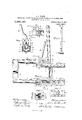
- Figure 1 is a perspective view of the improved pin puller, showing the same mounted upon an anvil.
- Fig. 2 is an enlarged longitudinal vertical sectional view of the same.
- Fig. 3 is a side view of the device illustrating the manner in which it is operated in withdrawing a pin from the shank end ofa drill bit.
- Fig. 4 is a plan view of Fig. 3.
- Fig. 5 is a transverse sectionalview on the line 55 of Fig. 3.
- Fig. 6, is :a detached perspective View of the Specification of Letters Patent.
- Fig. 7 is a plan view of the same.
- Fig. 8 is an edge view ofthe slide-block-operating lever.
- Fig. 9 is a bottom view of a portion of the puller, showing the cruciform shank which is adapted to enter the tool holding aperture in the anvil and thus the said puller upon the anvil.
- Fig. 10 is a perspective View illustrating a portion of a drill bit forming, sharpening and shanking machine having attached thereto a pin puller of slightly different construction.
- the numeral l designates the bed plate of my pin pulling machine.
- This bed plate is arranged and adapted to be removably supported on-an anvil 2 or to any other suitable support, in any suitable manner, and if desired to the drill sharpening machine itself.
- I preferably however illustrate it adapted to be supported on an anvil, and for this purpose provide it with a depending shank 3, which extends loosely into the tool holding aperture 4 of the anvil, the shank acting to support the machine on the anvil, and to prevent the bed plate of the pin pulling ma chinefrom being accidentally pushed off the anvil.
- the shank 3 is preferably cruciform in cross section, as shown by Fig.
- the frame 1 of my-pin pulling machine is an elongated square or blockshaped casting, and its top surface is provided with a T-shaped channel form of recess 6, that extends from its top surface 7, close to its bottom surface.
- This channel is provided with two oppositely extending side slotportions 8, which extend as side continuations of the open channel recess into the opposite side portions of the block-shaped frame, and they are adapted to form a slideway for a block 9, and for the opposite end portions of a movable pin 10, that is formed on the lower end of a hand-gripping pull lever 11, that is positioned in the channel, as will be presently described.
- the lower part 11 of the channel forms a clearance slot be tween two oppositely arranged step portions 12, in which a round form of ratchet toothed rack 13 is formed; the ratchet teeth lslare arranged opposite to each other and are adapted to receive the opposite ends of the pin 10 of the hand gripping pull.
- lever 11 as will be presently described.
- This channeled slot or recess extends from the rear end 15 of the frame to its front end, where an end abutment partition 16 is formed across it, which extends a short distance above the top portion of the frame.
- the upper edge of the partition is provided with a pin receiving slot. 17, that is positioned centrally of its width, and that txtends down close to the top of the frame.
- the slot 17 is arranged and adapted to receive the pin 18, that my machine is de signed to pull from the axial aperture in. the ends of bars of drill steel.
- the pin 18, when it is to be withdrawn, is laid in the slot with the end of the bar of drill steel 19 against the outside surface of the abutment end of the frame, and the pin projects centrally along the block-shaped frame and is adapted to be gripped by a cam 20, that is supported by the sliding block 9, which is slidably mounted in the side slots of the channel of the frame, as will be presently described.
- the sliding block 9 comprises a flat base portion 22, that is of a size to slide in the slide-way recesses of the channel of the block.
- A. raised lug portion 23 is formed. on the center of the block, to one end of which a pair of links 24 is pivo-tally attached by a pin 25, wl'iiclu'extends through them, slots 26 being formed through the base portion 22 to form clearance spaces for the links.
- the top portion of this lug portion adjacent to the ends of the links is provided with a semicircular shaped groove 27, which acts as a centering guide to the pin 18, and adjacent to the centering grooved portion of the lug.
- a recess 28 is formed, in which a steel grip block 29 is placed.
- this grip block is arranged in alinement with the bottom of the slot 17 in the end abutment of the frame, and on opposite sides of the central lug portion of the sliding block there is a pair of lugs 30, which projects above the central lug portion far enough to receive between them directly over the pin gripping block and in position to grip the drill steel pin 18 to release the same by a turning movement, the cam disk 20, which is formed on the end of a gripping handle This handle 32 is bent to one side of the plane of the cam disk far enough to allow it to pass by the pull lever 11, which is pivotally pinned to the opposite ends of the links.
- the peripheral surface of the cam disk is grooved to fit over the pin 18 and the surface of this groove and also the top surface of the grip block which lies directly under the cam disk, are serrated or knurled to form on them a pin gripping surface.
- the links 241- [it loosely in the top of the channel, and the hand pull lever, which is made considerably longer than the cam disk handle, extends down between them, and is pivotally pinned to them by a pin 33, and on thelower end of this pull lever the ratchet tooth engaging pin portion 10 is formed.
- the ratchet toothed is
- portions of the block-shaped frame comprise a plurality of ratchet teeth having semicircular recesses between them that are made large enough to receive the ends of the pin loosely, and the ratchet. teeth are inclined slightly away from the sliding block, and its pin gripping cam, and when the pull lever is given a reciprocal movement, of su'l'licient stroke to cause its pin end to rise from the bottom of the recesses bet-ween the ratchet teeth, the links cause its pin end to move forward step by step in the ratchet teeth and draw the sliding block along in its channel slot from the front pin inserting end portion of the block-shaped frame along its length to its opposite or rear end, or to a sutlicient part of its length to draw the pin out of the drill steel.
- the pins are very quickly withdrawn by the operators and without cutting into the pins, as follows: After a working treatment of the bar in the drill sharpener, the operator, having first mounted the pin puller on the anvil, inserts the pin in the slot 17 of the abutment 16 of the frame of the machine, and pushes it between the lugs 30 of the sliding block 9, underneath the cam disk, and until the end of the drill steel strikes against the end of the frame of the machine.
- Lugs 40 are formed on one side of the bar-shaped frame, that are bolted to the side of the drill sharpener machine adjacent to and slightly below the drill steel clamping vise jaws ll of the drill sharpener.
- the end of the bar frame in which the pin is inserted is of different shape than in the preferred construction, but it contains an abutment partition 42 and pin slot 43.
- the lower end of the pull lever is fixed and the pin is withdrawn by one sweeping movement of the pull lever, which is generally sutiicient, but in case it is not sufficient, the grip of the cam, which is the same as in the anvil type, is released, and the sliding block is moved farther along the pin toward the drill steel, which is again gripped by the cam and again moved by the pull lever.
- a pin puller comprising a supporting frame, having one closed end containing a slot adapted to receive the pin and provided with a channel slot extending from its closed end portion throughout its length, said channel being arranged to form a slideway, a ratchet toothed rack portion in said channel, a block slidably mounted in said slideway, means including a hand gripping cam connected to said block for gripping said pin, and a hand operating lever provided with a pin portion arranged to engage the ratchet teeth of said rack and reciprocally connected by a link connection to said block, whereby said block is caused to grip a pin and to be moved in successive step by step order along said rack as said hand grasping lever is operatively reciprocated.
- the combi nation of the pin supporting frame provided with'a depending lug adapted to lit the tool receiving aperture o1 an anvil, said pin supporting ttranie being provided with an end wall containing a recess through which the pin is adapted to extend, a ratchet toothed rack in said channel, a block slidinglv inoi' nled in said channel, said block being provided with a vertically arranged pair at wars, a hand gri ping cam pivoted between said ears, said block being provided with a recess between said cars, a steel grip block in said recess, provided with a knurled surface, said grip being adapted to receive a pin, and said hand gripping cam being arranged to grip said pin againstsaid grip block.
- the pin supporting :tranie provided with a T-shaped slidewav and with two oppositely arranged ratchet trothed racks in said slideway, an up wardly projecti partition at one end of said frame against which the ends of said drill steel are placed, said partition being provided with a slot througl'i which the pin to be pulled projects, a block slidably mounted in said l-shaped slideway, agrip block in said slideway block, a cam disk pivoted in said block in operative pin gripping relation to said grip block, a hand grip ping handle extending from said cam block, said cam and grip block being arranged to receive a pin between them, a hand grasping lever provided with a pin portion e2;- ttnding transversely across its lower end at right angles to its hand grasping portion, and on opposite sides of it, loosely in said 'l slet, and to mesh in the ratchet
- a pin puller as specified, a stationary support, a pin gripping device slidably mounted in the support, a lever in swing ing connection with the pin gripping device, and a series of abutments in the support adapted to be successively engaged by the lower end of the lever in sliding the pin gripping device.
- a pin puller as specified, a stationary support having notched parallel slideways, a pin gripper mounted on said slideways, a lever the lower end of which is adapted to successively engage the notches in said slideway, and lin ⁇ S connecting the lever wi th the pin gripper.
- a stationary support having an abutment at one end provided with a pin receiving recess, notched parallel slideways extending longitudinally of the support, a pin gripper on the slideways in axial line with the said, pin-receiving recess, a lever the lower end of which extends between the said slideways, and having lateral project-ions adapted to successively engage the said notches, and links connecting the lever and pin gripper.
- a pin puller as specified, the combination with a stationary support having longitudinally disposed notched parallel slideways, and an abutment at one end having a vertical pin-receiving recess, of a pin gripper mounted on said slideways, comprising a slidable block having a grooved pin receiving face, and a gripping cam pivotally mounted on the block in cooperative relation with its grooved :tace, a lever the low r end of which lies between the said notched slideways, and having laterally projecting lugs adapted to successively en gage the said notches, and links connecting the lever with the block portion of the pin gripper.
- a pin puller as specified, the combination with a stationary support having a pin gripper slidably mounted therein, and a series of tulcrum abutments, of a lever connected to said pin gripper and adapted to successively engage said fulcrum abutments.
Landscapes
- Engineering & Computer Science (AREA)
- Mechanical Engineering (AREA)
- Drilling And Boring (AREA)
Description
J. Q. GRANT. PIN PULLING MACHINE FOR USE IN FORGING THE SHANK ENDS 0P DRILL STEEL.
APPLICATION FILED AUG. 30, 1912.
3 SHEETS-SHEET 1.
Patented June 17, 1913.
a. J? 6 awa Wf 'fizea-seSk QQZLwL7 nm COLUMBIA PLANOORAPH c0..wAsI-uNn'roN, D4 c J. Q. GRANT. PIN PULLING MACHINE FOR USE IN FORGING THE SHANK ENDS 0F DRILL STEEL. APPLICATION FILED AUG. 30, 1912.
1,065,125, Patented June 17,1913.
EC? .4. i2
IH-HI'IIII COLUMBIA PLANOGRAPII CO.,WASHINGTDN. 0. c.
J. Q. GRANT. PIN PULLING MACHINE FOR USE IN FORGING THE SHANK ENDS 0F DRILL STEEL. APPLICATION FILED AUG, 30, 1912.
1,065,125. Patented June 17, 1913.
3 SHEETS-SHEET 3.
75276-8618: Q Q .M 1?
CULUIHULA -msuulupn (ID-,VASHINGTON, o.c.
jzoen-or UNITED STATES PATENT OFFIC.
JOHN o. GRANT, or DENVER, COLORADO.
PIN-PULLING MACHINE FOR USE IN FORGING THE SHANK ENDS OF DRILL-STEEL.
To all whom it may concern Be it known that 1, JOHN Q. GRANT, a citizen of the United States of America, residing in the city and county of Denver and State of Colorado, have invented a new and useful Pin-Pulling 'Machine for Use in Forging the Shank Ends of DrillSteel of which the following is a specification.
My :invention relates to a machine for pulling out from the heated ends of hollow drill steel, the pin inserted therein to maintain the size of the axial aperture in the hollow drill steel, from which rock cutting drill bits are made, while forging upon one end of their bars a shank end that is adapted to fit the drill bit holding chucks of rock drilling engines, these rock cutting drill bits being forged in machines entitled Fluid actuated drill-bit forming, sharpening and shanking machines, a description and illustration of which may be found in the pendiing application Serial Number 686,133, filed March 25, 1912, which machine and the shanking dies thereof were especially designed for the forming of the chuck holding shank ends of hollow drill bits; and my :present invention contemplates a machine lower end of the said lever in withdrawing a pin from the shank end of a drill bit. These objects are accomplished by the device illus trated in the accompanying drawings, in which:
Figure 1, is a perspective view of the improved pin puller, showing the same mounted upon an anvil. Fig. 2, is an enlarged longitudinal vertical sectional view of the same. Fig. 3, isa side view of the device illustrating the manner in which it is operated in withdrawing a pin from the shank end ofa drill bit. Fig. 4, is a plan view of Fig. 3. Fig. 5, is a transverse sectionalview on the line 55 of Fig. 3. Fig. 6, is :a detached perspective View of the Specification of Letters Patent.
Application filed August 30,51912.
Patentec'l June 1'7, 1913. Serial No. 717,902.
slide block to which the pin-clamping cam ispivotally attached. Fig. 7, is a plan view of the same. Fig. 8, is an edge view ofthe slide-block-operating lever. Fig. 9, is a bottom view of a portion of the puller, showing the cruciform shank which is adapted to enter the tool holding aperture in the anvil and thus the said puller upon the anvil. And Fig. 10, is a perspective View illustrating a portion of a drill bit forming, sharpening and shanking machine having attached thereto a pin puller of slightly different construction.
Similar letters of reference refer to similar parts throughout the several views.
Referring to the drawings,the numeral ldesignates the bed plate of my pin pulling machine. This bed plate is arranged and adapted to be removably supported on-an anvil 2 or to any other suitable support, in any suitable manner, and if desired to the drill sharpening machine itself. I preferably however illustrate it adapted to be supported on an anvil, and for this purpose provide it with a depending shank 3, which extends loosely into the tool holding aperture 4 of the anvil, the shank acting to support the machine on the anvil, and to prevent the bed plate of the pin pulling ma chinefrom being accidentally pushed off the anvil. The shank 3 is preferably cruciform in cross section, as shown by Fig. 9, which enables it to be more readily and easily filed to fit the tool receiving aperture in the anvil when necessary, than would be the case were the said shank solid or square in cross section. It is not necessar that the bed plate be secured rigidly to the anvil, although it may be if desired, the idea being that with my pin-puller it can be placed quickly on an anvil, while a number of bars of drill steel are having shank end lugs 5 formed on them, in the drill sharpening machine above mentioned, after which the machine may be removed from the anvil and be laid to one side until it is again desired to use it when making up another lot of shank ends on bars of hollow drill steel in the process of making up a lot of rock cutting drill bits.
The frame 1 of my-pin pulling machine is an elongated square or blockshaped casting, and its top surface is provided with a T-shaped channel form of recess 6, that extends from its top surface 7, close to its bottom surface. This channel is provided with two oppositely extending side slotportions 8, which extend as side continuations of the open channel recess into the opposite side portions of the block-shaped frame, and they are adapted to form a slideway for a block 9, and for the opposite end portions of a movable pin 10, that is formed on the lower end of a hand-gripping pull lever 11, that is positioned in the channel, as will be presently described. The lower part 11 of the channel, forms a clearance slot be tween two oppositely arranged step portions 12, in which a round form of ratchet toothed rack 13 is formed; the ratchet teeth lslare arranged opposite to each other and are adapted to receive the opposite ends of the pin 10 of the hand gripping pull. lever 11, as will be presently described. This channeled slot or recess extends from the rear end 15 of the frame to its front end, where an end abutment partition 16 is formed across it, which extends a short distance above the top portion of the frame. The upper edge of the partition is provided with a pin receiving slot. 17, that is positioned centrally of its width, and that txtends down close to the top of the frame. The slot 17 is arranged and adapted to receive the pin 18, that my machine is de signed to pull from the axial aperture in. the ends of bars of drill steel. The pin 18, when it is to be withdrawn, is laid in the slot with the end of the bar of drill steel 19 against the outside surface of the abutment end of the frame, and the pin projects centrally along the block-shaped frame and is adapted to be gripped by a cam 20, that is supported by the sliding block 9, which is slidably mounted in the side slots of the channel of the frame, as will be presently described.
The sliding block 9 comprises a flat base portion 22, that is of a size to slide in the slide-way recesses of the channel of the block. A. raised lug portion 23 is formed. on the center of the block, to one end of which a pair of links 24 is pivo-tally attached by a pin 25, wl'iiclu'extends through them, slots 26 being formed through the base portion 22 to form clearance spaces for the links. The top portion of this lug portion adjacent to the ends of the links, is provided with a semicircular shaped groove 27, which acts as a centering guide to the pin 18, and adjacent to the centering grooved portion of the lug. a recess 28 is formed, in which a steel grip block 29 is placed. The top surface of this grip block is arranged in alinement with the bottom of the slot 17 in the end abutment of the frame, and on opposite sides of the central lug portion of the sliding block there is a pair of lugs 30, which projects above the central lug portion far enough to receive between them directly over the pin gripping block and in position to grip the drill steel pin 18 to release the same by a turning movement, the cam disk 20, which is formed on the end of a gripping handle This handle 32 is bent to one side of the plane of the cam disk far enough to allow it to pass by the pull lever 11, which is pivotally pinned to the opposite ends of the links. The peripheral surface of the cam disk is grooved to fit over the pin 18 and the surface of this groove and also the top surface of the grip block which lies directly under the cam disk, are serrated or knurled to form on them a pin gripping surface. The links 241-, [it loosely in the top of the channel, and the hand pull lever, which is made considerably longer than the cam disk handle, extends down between them, and is pivotally pinned to them by a pin 33, and on thelower end of this pull lever the ratchet tooth engaging pin portion 10 is formed. The ratchet toothed. portions of the block-shaped frame comprise a plurality of ratchet teeth having semicircular recesses between them that are made large enough to receive the ends of the pin loosely, and the ratchet. teeth are inclined slightly away from the sliding block, and its pin gripping cam, and when the pull lever is given a reciprocal movement, of su'l'licient stroke to cause its pin end to rise from the bottom of the recesses bet-ween the ratchet teeth, the links cause its pin end to move forward step by step in the ratchet teeth and draw the sliding block along in its channel slot from the front pin inserting end portion of the block-shaped frame along its length to its opposite or rear end, or to a sutlicient part of its length to draw the pin out of the drill steel.
The operation of my pin puller is as f0llows; but inasmuch as this pin pulling operation is a side treatment in the process of forming the chuck locking lugs on the shank ends of drill steel when making drill bits, a description of the forging treatment is necessary to clearly understand when and where and how the pin puller is used. In the above mentioned pending application, Serial No. 686,133, a drill sharpener that is adapted to form the locking lugs 5 on bars of drill steel 19 and to size the shank ends of bars.
of hollow drill steel which are to be formed into drill bits, is shown. In the operation of that mechanism and in this operation, the bars are first heated to a forging heat, which it is necessary to renew several times during the process, as it requires several intermittent and successive forging treatments in the drill sharpener to form and finish the locking lugs and size the shank end of the drill steel, and between each treatment each bar is reheated, as the bars cool rapidly during each working in the machine, and as, it is necessary that the axial aperture through the ends of the hollow drill steel be kept open, a cold steel pin 18, is driven into the shank end of the heated end of each bar of drill steel just before it is subjected to working treatment in the machine, and these pins are made long enough to project several inches beyond the end of the drill steel after being driven into it beyond the point where the locking lugs 5 are formed, and it is necessary to pull this cold pin out .after each working treatment and reheat the drill steel, and after reheating each bar to drive a cold steel pin back into its end, and as this opera tion has to be repeated several times, the pulling out of this pin is an important feature of the operation.
Prior to the invention of my pin pulling machine, it was necessary to drive this pin out by hand, which was done by one man holding the bar of drill steel by one hand with tongs and laying the pin on the anvil and holding a chisel against it with the other hand, at a slanting angle to move the pin out, and another operator striking the chisel with sledge hammer, which operation was slow and tedious and resulted in cutting and destroying the pins after re peated use, as the hot bars shrank on them during the slow action of driving them out sutliciently to make it difficult to dislodge them. \Vith my machine the pins are very quickly withdrawn by the operators and without cutting into the pins, as follows: After a working treatment of the bar in the drill sharpener, the operator, having first mounted the pin puller on the anvil, inserts the pin in the slot 17 of the abutment 16 of the frame of the machine, and pushes it between the lugs 30 of the sliding block 9, underneath the cam disk, and until the end of the drill steel strikes against the end of the frame of the machine. He then grasps the handleof the cam disk and throws it over 'toward the pull lever, which causes the cam to force the pin against the grip block and to grip and hold it down hard against the grip block, and pressure is applied continuously to the handle while the operator grasps thepull lever and moves it toward the sliding block far enough to lift its pin end out of the recess of the ratchet teeth it is in, and moves it away from the sliding block over the adjacent oppositely arranged ratchet teeth into the next recess, and then moves the handle end of the pull lever away from the sliding block, which action moves the-sliding block through the medium of the links along its slide-way and draws the pin with it a distance equal to pitch of the ratchet teeth and the relative stroke movement of the pull lever, and the operator repeats this reciprocal movement of the pull lever and feeds its pin end along the ratchet toothed rack step by step and draws the pin step by step out of the end of the drill steel, and as this pull lever can be reciprocated quickly, the pin is very quickly withdrawn from the drill steel. The opposite ends of long bars of drill steel are supported by any floor rest, such as the rest 37.
While I have illustrated my improved pin puller adapted to rest on an anvil, it can be if desired secured directly to the clamping vise side of the drill sharpening machine, by modifying its shape to fit the machine, and in Fig. 1.0 I have illustrated a modification of the puller that will fit the machine. In this modification, a bar shaped frame 38 is substituted for the frame, and a sliding .block 39 of different shape is reciprocally mount-ed on the bar, while the pin portion of the pull lever is dispensed with and the end of the pull lever is pivotally attached to one end of the barshaped frame. The ratchet toothed racks are also dispensed with upon the side. Lugs 40 are formed on one side of the bar-shaped frame, that are bolted to the side of the drill sharpener machine adjacent to and slightly below the drill steel clamping vise jaws ll of the drill sharpener. The end of the bar frame in which the pin is inserted, is of different shape than in the preferred construction, but it contains an abutment partition 42 and pin slot 43. In this modification the lower end of the pull lever is fixed and the pin is withdrawn by one sweeping movement of the pull lever, which is generally sutiicient, but in case it is not sufficient, the grip of the cam, which is the same as in the anvil type, is released, and the sliding block is moved farther along the pin toward the drill steel, which is again gripped by the cam and again moved by the pull lever.
My invention makes a simple and practical pin puller, and while I have illustrated and described the preferred construction of the same, I do not wish to be limited to the construction and arrangement shown, as many changes might be made without departing from the scope of the claims.
Having described my invention, what I claim as new and desire to secure by Letters Patent, is:
i. A pin puller comprising a supporting frame, having one closed end containing a slot adapted to receive the pin and provided with a channel slot extending from its closed end portion throughout its length, said channel being arranged to form a slideway, a ratchet toothed rack portion in said channel, a block slidably mounted in said slideway, means including a hand gripping cam connected to said block for gripping said pin, and a hand operating lever provided with a pin portion arranged to engage the ratchet teeth of said rack and reciprocally connected by a link connection to said block, whereby said block is caused to grip a pin and to be moved in successive step by step order along said rack as said hand grasping lever is operatively reciprocated.
In a pin puller as specified, the combi nation of the pin supporting frame provided with'a depending lug adapted to lit the tool receiving aperture o1 an anvil, said pin supporting ttranie being provided with an end wall containing a recess through which the pin is adapted to extend, a ratchet toothed rack in said channel, a block slidinglv inoi' nled in said channel, said block being provided with a vertically arranged pair at wars, a hand gri ping cam pivoted between said ears, said block being provided with a recess between said cars, a steel grip block in said recess, provided with a knurled surface, said grip being adapted to receive a pin, and said hand gripping cam being arranged to grip said pin againstsaid grip block.
lin a pin puller as specified, the coi'nbination ol the frame provided with the slideway, the sliding block reciprocally mounted in the slideway of said frame, the hand gripping can] mounted on said block, and the pin gripping block in. said sliding block below said am, said gripping block and cam being arranged to receive and grip a pin between them, with a pair of links secured at one end to said sliding block, a hand pull lever -tecured intermediate of its ends to the opposite ends of .raid links, and an abutment tor the hand pull lever on said frame, wheriby when said pull lever is reciprocated said sliding block is moved on the slideway of said frame.
4. in a pin pulling machine for pulling the pins from hollow drill steel as specified, the combination of the pin supporting :tranie provided with a T-shaped slidewav and with two oppositely arranged ratchet trothed racks in said slideway, an up wardly projecti partition at one end of said frame against which the ends of said drill steel are placed, said partition being provided with a slot througl'i which the pin to be pulled projects, a block slidably mounted in said l-shaped slideway, agrip block in said slideway block, a cam disk pivoted in said block in operative pin gripping relation to said grip block, a hand grip ping handle extending from said cam block, said cam and grip block being arranged to receive a pin between them, a hand grasping lever provided with a pin portion e2;- ttnding transversely across its lower end at right angles to its hand grasping portion, and on opposite sides of it, loosely in said 'l slet, and to mesh in the ratchet teeth of said ratchet toothed racks, and a pair of links pivctally secured to the opposite sides or said hanu grasping lever at one ot' their ends and pivctally secured at their opposite ends to said sliding block, said links being arranged and adapt-d to permit said hand grasping lever to be reciprocated and its lower end to be raised out of engagement with one ratchet tooth and moved forward into engagement with the next ratchet teeth, as it; is lClP1'OC2ttQl, and to thus move said sliding block step by step in the slideway of said .t'ran e.
lin a pin puller as specified, a stationary support, a pin gripping device slidably mounted in the support, a lever in swing ing connection with the pin gripping device, and a series of abutments in the support adapted to be successively engaged by the lower end of the lever in sliding the pin gripping device.
(3. In a pin puller as specified, a stationary support having notched parallel slideways, a pin gripper mounted on said slideways, a lever the lower end of which is adapted to successively engage the notches in said slideway, and lin {S connecting the lever wi th the pin gripper.
t. In a pin puller specified, a stationary support having an abutment at one end provided with a pin receiving recess, notched parallel slideways extending longitudinally of the support, a pin gripper on the slideways in axial line with the said, pin-receiving recess, a lever the lower end of which extends between the said slideways, and having lateral project-ions adapted to successively engage the said notches, and links connecting the lever and pin gripper.
8. In a pin puller as specified, the combination with a stationary support having longitudinally disposed notched parallel slideways, and an abutment at one end having a vertical pin-receiving recess, of a pin gripper mounted on said slideways, comprising a slidable block having a grooved pin receiving face, and a gripping cam pivotally mounted on the block in cooperative relation with its grooved :tace, a lever the low r end of which lies between the said notched slideways, and having laterally projecting lugs adapted to successively en gage the said notches, and links connecting the lever with the block portion of the pin gripper.
f). In a pin puller as specified, the combination with a stationary support having a pin gripper slidably mounted therein, and a series of tulcrum abutments, of a lever connected to said pin gripper and adapted to successively engage said fulcrum abutments.
In testimony whereof I atlix my signature in presence of two witnesses.
JOHN Q. GRANT.
Witnesses Jenn Gnonon Lnrnn, Fnnnnmon il Knownenno.
Copies of this patent may be obtained. for five cents each, by addressing the Commissioner of Patents, Washington, D. C.
Priority Applications (1)
| Application Number | Priority Date | Filing Date | Title |
|---|---|---|---|
| US71790212A US1065125A (en) | 1912-08-30 | 1912-08-30 | Pin-pulling machine for use in forging the shank ends of drill-steel. |
Applications Claiming Priority (1)
| Application Number | Priority Date | Filing Date | Title |
|---|---|---|---|
| US71790212A US1065125A (en) | 1912-08-30 | 1912-08-30 | Pin-pulling machine for use in forging the shank ends of drill-steel. |
Publications (1)
| Publication Number | Publication Date |
|---|---|
| US1065125A true US1065125A (en) | 1913-06-17 |
Family
ID=3133368
Family Applications (1)
| Application Number | Title | Priority Date | Filing Date |
|---|---|---|---|
| US71790212A Expired - Lifetime US1065125A (en) | 1912-08-30 | 1912-08-30 | Pin-pulling machine for use in forging the shank ends of drill-steel. |
Country Status (1)
| Country | Link |
|---|---|
| US (1) | US1065125A (en) |
-
1912
- 1912-08-30 US US71790212A patent/US1065125A/en not_active Expired - Lifetime
Similar Documents
| Publication | Publication Date | Title |
|---|---|---|
| US960300A (en) | Wire-stitching instrument. | |
| US2511843A (en) | Screw-actuated vise jaw quickly | |
| US3336655A (en) | Die structure | |
| US2564585A (en) | Pliers or wrench with automatic adjusting and locking means | |
| US669605A (en) | Cam-and-ratchet vise. | |
| US1596464A (en) | Tube-extracting jack | |
| US661798A (en) | Apparatus for making and sharpening rock-drills. | |
| US1565776A (en) | Press | |
| US433794A (en) | Wrench | |
| US1395702A (en) | Shank and bit punch | |
| US363041A (en) | shevlw | |
| USRE12614E (en) | Reissued mar | |
| US168135A (en) | Improvement in machines for forging wrench-bar heads | |
| US823155A (en) | Wrench. | |
| US380734A (en) | William l | |
| US1249587A (en) | Adjustable wrench. | |
| US1191176A (en) | Tie-cutter. | |
| US927181A (en) | Rock-drill making and sharpening machine. | |
| US1098474A (en) | Machine for making and sharpening rock-drills and for general forging. | |
| US348037A (en) | Machine for splitting the tangs and forming the sockets of shovel-blanks | |
| US952634A (en) | Monkey-wrench. | |
| US753386A (en) | Spike-puller | |
| US1347360A (en) | Portable clamp | |
| US929466A (en) | Tool holder or chuck. | |
| US1201010A (en) | Combined tool holder and plunger. |