US10648437B2 - Fuel pump - Google Patents
Fuel pump Download PDFInfo
- Publication number
- US10648437B2 US10648437B2 US16/300,343 US201716300343A US10648437B2 US 10648437 B2 US10648437 B2 US 10648437B2 US 201716300343 A US201716300343 A US 201716300343A US 10648437 B2 US10648437 B2 US 10648437B2
- Authority
- US
- United States
- Prior art keywords
- inlet
- fluid communication
- pressure
- high pressure
- fuel
- Prior art date
- Legal status (The legal status is an assumption and is not a legal conclusion. Google has not performed a legal analysis and makes no representation as to the accuracy of the status listed.)
- Active
Links
Images


Classifications
-
- F—MECHANICAL ENGINEERING; LIGHTING; HEATING; WEAPONS; BLASTING
- F02—COMBUSTION ENGINES; HOT-GAS OR COMBUSTION-PRODUCT ENGINE PLANTS
- F02M—SUPPLYING COMBUSTION ENGINES IN GENERAL WITH COMBUSTIBLE MIXTURES OR CONSTITUENTS THEREOF
- F02M59/00—Pumps specially adapted for fuel-injection and not provided for in groups F02M39/00 -F02M57/00, e.g. rotary cylinder-block type of pumps
- F02M59/02—Pumps specially adapted for fuel-injection and not provided for in groups F02M39/00 -F02M57/00, e.g. rotary cylinder-block type of pumps of reciprocating-piston or reciprocating-cylinder type
- F02M59/022—Pumps specially adapted for fuel-injection and not provided for in groups F02M39/00 -F02M57/00, e.g. rotary cylinder-block type of pumps of reciprocating-piston or reciprocating-cylinder type having an accumulator storing pressurised fuel during pumping stroke of the piston for subsequent delivery to the injector
-
- F—MECHANICAL ENGINEERING; LIGHTING; HEATING; WEAPONS; BLASTING
- F02—COMBUSTION ENGINES; HOT-GAS OR COMBUSTION-PRODUCT ENGINE PLANTS
- F02M—SUPPLYING COMBUSTION ENGINES IN GENERAL WITH COMBUSTIBLE MIXTURES OR CONSTITUENTS THEREOF
- F02M59/00—Pumps specially adapted for fuel-injection and not provided for in groups F02M39/00 -F02M57/00, e.g. rotary cylinder-block type of pumps
- F02M59/44—Details, components parts, or accessories not provided for in, or of interest apart from, the apparatus of groups F02M59/02 - F02M59/42; Pumps having transducers, e.g. to measure displacement of pump rack or piston
- F02M59/46—Valves
- F02M59/464—Inlet valves of the check valve type
-
- F—MECHANICAL ENGINEERING; LIGHTING; HEATING; WEAPONS; BLASTING
- F02—COMBUSTION ENGINES; HOT-GAS OR COMBUSTION-PRODUCT ENGINE PLANTS
- F02M—SUPPLYING COMBUSTION ENGINES IN GENERAL WITH COMBUSTIBLE MIXTURES OR CONSTITUENTS THEREOF
- F02M37/00—Apparatus or systems for feeding liquid fuel from storage containers to carburettors or fuel-injection apparatus; Arrangements for purifying liquid fuel specially adapted for, or arranged on, internal-combustion engines
- F02M37/0011—Constructional details; Manufacturing or assembly of elements of fuel systems; Materials therefor
- F02M37/0023—Valves in the fuel supply and return system
-
- F—MECHANICAL ENGINEERING; LIGHTING; HEATING; WEAPONS; BLASTING
- F02—COMBUSTION ENGINES; HOT-GAS OR COMBUSTION-PRODUCT ENGINE PLANTS
- F02M—SUPPLYING COMBUSTION ENGINES IN GENERAL WITH COMBUSTIBLE MIXTURES OR CONSTITUENTS THEREOF
- F02M59/00—Pumps specially adapted for fuel-injection and not provided for in groups F02M39/00 -F02M57/00, e.g. rotary cylinder-block type of pumps
- F02M59/20—Varying fuel delivery in quantity or timing
- F02M59/205—Quantity of fuel admitted to pumping elements being metered by an auxiliary metering device
-
- F—MECHANICAL ENGINEERING; LIGHTING; HEATING; WEAPONS; BLASTING
- F02—COMBUSTION ENGINES; HOT-GAS OR COMBUSTION-PRODUCT ENGINE PLANTS
- F02M—SUPPLYING COMBUSTION ENGINES IN GENERAL WITH COMBUSTIBLE MIXTURES OR CONSTITUENTS THEREOF
- F02M59/00—Pumps specially adapted for fuel-injection and not provided for in groups F02M39/00 -F02M57/00, e.g. rotary cylinder-block type of pumps
- F02M59/20—Varying fuel delivery in quantity or timing
- F02M59/34—Varying fuel delivery in quantity or timing by throttling of passages to pumping elements or of overflow passages, e.g. throttling by means of a pressure-controlled sliding valve having liquid stop or abutment
-
- F—MECHANICAL ENGINEERING; LIGHTING; HEATING; WEAPONS; BLASTING
- F02—COMBUSTION ENGINES; HOT-GAS OR COMBUSTION-PRODUCT ENGINE PLANTS
- F02M—SUPPLYING COMBUSTION ENGINES IN GENERAL WITH COMBUSTIBLE MIXTURES OR CONSTITUENTS THEREOF
- F02M59/00—Pumps specially adapted for fuel-injection and not provided for in groups F02M39/00 -F02M57/00, e.g. rotary cylinder-block type of pumps
- F02M59/44—Details, components parts, or accessories not provided for in, or of interest apart from, the apparatus of groups F02M59/02 - F02M59/42; Pumps having transducers, e.g. to measure displacement of pump rack or piston
- F02M59/46—Valves
-
- F—MECHANICAL ENGINEERING; LIGHTING; HEATING; WEAPONS; BLASTING
- F02—COMBUSTION ENGINES; HOT-GAS OR COMBUSTION-PRODUCT ENGINE PLANTS
- F02M—SUPPLYING COMBUSTION ENGINES IN GENERAL WITH COMBUSTIBLE MIXTURES OR CONSTITUENTS THEREOF
- F02M63/00—Other fuel-injection apparatus having pertinent characteristics not provided for in groups F02M39/00 - F02M57/00 or F02M67/00; Details, component parts, or accessories of fuel-injection apparatus, not provided for in, or of interest apart from, the apparatus of groups F02M39/00 - F02M61/00 or F02M67/00; Combination of fuel pump with other devices, e.g. lubricating oil pump
- F02M63/0012—Valves
- F02M63/0031—Valves characterized by the type of valves, e.g. special valve member details, valve seat details, valve housing details
- F02M63/004—Sliding valves, e.g. spool valves, i.e. whereby the closing member has a sliding movement along a seat for opening and closing
- F02M63/0042—Sliding valves, e.g. spool valves, i.e. whereby the closing member has a sliding movement along a seat for opening and closing combined with valve seats of the lift valve type
-
- F—MECHANICAL ENGINEERING; LIGHTING; HEATING; WEAPONS; BLASTING
- F02—COMBUSTION ENGINES; HOT-GAS OR COMBUSTION-PRODUCT ENGINE PLANTS
- F02M—SUPPLYING COMBUSTION ENGINES IN GENERAL WITH COMBUSTIBLE MIXTURES OR CONSTITUENTS THEREOF
- F02M63/00—Other fuel-injection apparatus having pertinent characteristics not provided for in groups F02M39/00 - F02M57/00 or F02M67/00; Details, component parts, or accessories of fuel-injection apparatus, not provided for in, or of interest apart from, the apparatus of groups F02M39/00 - F02M61/00 or F02M67/00; Combination of fuel pump with other devices, e.g. lubricating oil pump
- F02M63/0012—Valves
- F02M63/0031—Valves characterized by the type of valves, e.g. special valve member details, valve seat details, valve housing details
- F02M63/005—Pressure relief valves
-
- F—MECHANICAL ENGINEERING; LIGHTING; HEATING; WEAPONS; BLASTING
- F04—POSITIVE - DISPLACEMENT MACHINES FOR LIQUIDS; PUMPS FOR LIQUIDS OR ELASTIC FLUIDS
- F04B—POSITIVE-DISPLACEMENT MACHINES FOR LIQUIDS; PUMPS
- F04B1/00—Multi-cylinder machines or pumps characterised by number or arrangement of cylinders
- F04B1/04—Multi-cylinder machines or pumps characterised by number or arrangement of cylinders having cylinders in star- or fan-arrangement
- F04B1/053—Multi-cylinder machines or pumps characterised by number or arrangement of cylinders having cylinders in star- or fan-arrangement with actuating or actuated elements at the inner ends of the cylinders
-
- F—MECHANICAL ENGINEERING; LIGHTING; HEATING; WEAPONS; BLASTING
- F04—POSITIVE - DISPLACEMENT MACHINES FOR LIQUIDS; PUMPS FOR LIQUIDS OR ELASTIC FLUIDS
- F04B—POSITIVE-DISPLACEMENT MACHINES FOR LIQUIDS; PUMPS
- F04B1/00—Multi-cylinder machines or pumps characterised by number or arrangement of cylinders
- F04B1/04—Multi-cylinder machines or pumps characterised by number or arrangement of cylinders having cylinders in star- or fan-arrangement
- F04B1/06—Control
- F04B1/08—Control regulated by delivery pressure
-
- F—MECHANICAL ENGINEERING; LIGHTING; HEATING; WEAPONS; BLASTING
- F04—POSITIVE - DISPLACEMENT MACHINES FOR LIQUIDS; PUMPS FOR LIQUIDS OR ELASTIC FLUIDS
- F04B—POSITIVE-DISPLACEMENT MACHINES FOR LIQUIDS; PUMPS
- F04B49/00—Control, e.g. of pump delivery, or pump pressure of, or safety measures for, machines, pumps, or pumping installations, not otherwise provided for, or of interest apart from, groups F04B1/00 - F04B47/00
- F04B49/08—Regulating by delivery pressure
-
- F—MECHANICAL ENGINEERING; LIGHTING; HEATING; WEAPONS; BLASTING
- F04—POSITIVE - DISPLACEMENT MACHINES FOR LIQUIDS; PUMPS FOR LIQUIDS OR ELASTIC FLUIDS
- F04B—POSITIVE-DISPLACEMENT MACHINES FOR LIQUIDS; PUMPS
- F04B49/00—Control, e.g. of pump delivery, or pump pressure of, or safety measures for, machines, pumps, or pumping installations, not otherwise provided for, or of interest apart from, groups F04B1/00 - F04B47/00
- F04B49/22—Control, e.g. of pump delivery, or pump pressure of, or safety measures for, machines, pumps, or pumping installations, not otherwise provided for, or of interest apart from, groups F04B1/00 - F04B47/00 by means of valves
-
- F—MECHANICAL ENGINEERING; LIGHTING; HEATING; WEAPONS; BLASTING
- F04—POSITIVE - DISPLACEMENT MACHINES FOR LIQUIDS; PUMPS FOR LIQUIDS OR ELASTIC FLUIDS
- F04B—POSITIVE-DISPLACEMENT MACHINES FOR LIQUIDS; PUMPS
- F04B53/00—Component parts, details or accessories not provided for in, or of interest apart from, groups F04B1/00 - F04B23/00 or F04B39/00 - F04B47/00
- F04B53/16—Casings; Cylinders; Cylinder liners or heads; Fluid connections
-
- F—MECHANICAL ENGINEERING; LIGHTING; HEATING; WEAPONS; BLASTING
- F04—POSITIVE - DISPLACEMENT MACHINES FOR LIQUIDS; PUMPS FOR LIQUIDS OR ELASTIC FLUIDS
- F04B—POSITIVE-DISPLACEMENT MACHINES FOR LIQUIDS; PUMPS
- F04B7/00—Piston machines or pumps characterised by having positively-driven valving
- F04B7/02—Piston machines or pumps characterised by having positively-driven valving the valving being fluid-actuated
-
- F—MECHANICAL ENGINEERING; LIGHTING; HEATING; WEAPONS; BLASTING
- F04—POSITIVE - DISPLACEMENT MACHINES FOR LIQUIDS; PUMPS FOR LIQUIDS OR ELASTIC FLUIDS
- F04B—POSITIVE-DISPLACEMENT MACHINES FOR LIQUIDS; PUMPS
- F04B9/00—Piston machines or pumps characterised by the driving or driven means to or from their working members
- F04B9/02—Piston machines or pumps characterised by the driving or driven means to or from their working members the means being mechanical
- F04B9/04—Piston machines or pumps characterised by the driving or driven means to or from their working members the means being mechanical the means being cams, eccentrics or pin-and-slot mechanisms
- F04B9/042—Piston machines or pumps characterised by the driving or driven means to or from their working members the means being mechanical the means being cams, eccentrics or pin-and-slot mechanisms the means being cams
-
- F—MECHANICAL ENGINEERING; LIGHTING; HEATING; WEAPONS; BLASTING
- F02—COMBUSTION ENGINES; HOT-GAS OR COMBUSTION-PRODUCT ENGINE PLANTS
- F02D—CONTROLLING COMBUSTION ENGINES
- F02D1/00—Controlling fuel-injection pumps, e.g. of high pressure injection type
- F02D2001/0085—Arrangements using fuel pressure for controlling fuel delivery in quantity or timing
-
- F—MECHANICAL ENGINEERING; LIGHTING; HEATING; WEAPONS; BLASTING
- F02—COMBUSTION ENGINES; HOT-GAS OR COMBUSTION-PRODUCT ENGINE PLANTS
- F02M—SUPPLYING COMBUSTION ENGINES IN GENERAL WITH COMBUSTIBLE MIXTURES OR CONSTITUENTS THEREOF
- F02M39/00—Arrangements of fuel-injection apparatus with respect to engines; Pump drives adapted to such arrangements
- F02M39/005—Arrangements of fuel feed-pumps with respect to fuel injection apparatus
-
- F—MECHANICAL ENGINEERING; LIGHTING; HEATING; WEAPONS; BLASTING
- F02—COMBUSTION ENGINES; HOT-GAS OR COMBUSTION-PRODUCT ENGINE PLANTS
- F02M—SUPPLYING COMBUSTION ENGINES IN GENERAL WITH COMBUSTIBLE MIXTURES OR CONSTITUENTS THEREOF
- F02M55/00—Fuel-injection apparatus characterised by their fuel conduits or their venting means; Arrangements of conduits between fuel tank and pump F02M37/00
- F02M55/02—Conduits between injection pumps and injectors, e.g. conduits between pump and common-rail or conduits between common-rail and injectors
- F02M55/025—Common rails
-
- F—MECHANICAL ENGINEERING; LIGHTING; HEATING; WEAPONS; BLASTING
- F04—POSITIVE - DISPLACEMENT MACHINES FOR LIQUIDS; PUMPS FOR LIQUIDS OR ELASTIC FLUIDS
- F04B—POSITIVE-DISPLACEMENT MACHINES FOR LIQUIDS; PUMPS
- F04B17/00—Pumps characterised by combination with, or adaptation to, specific driving engines or motors
- F04B17/05—Pumps characterised by combination with, or adaptation to, specific driving engines or motors driven by internal-combustion engines
-
- F—MECHANICAL ENGINEERING; LIGHTING; HEATING; WEAPONS; BLASTING
- F04—POSITIVE - DISPLACEMENT MACHINES FOR LIQUIDS; PUMPS FOR LIQUIDS OR ELASTIC FLUIDS
- F04B—POSITIVE-DISPLACEMENT MACHINES FOR LIQUIDS; PUMPS
- F04B2203/00—Motor parameters
- F04B2203/06—Motor parameters of internal combustion engines
- F04B2203/0604—Power
-
- F—MECHANICAL ENGINEERING; LIGHTING; HEATING; WEAPONS; BLASTING
- F04—POSITIVE - DISPLACEMENT MACHINES FOR LIQUIDS; PUMPS FOR LIQUIDS OR ELASTIC FLUIDS
- F04B—POSITIVE-DISPLACEMENT MACHINES FOR LIQUIDS; PUMPS
- F04B2205/00—Fluid parameters
- F04B2205/03—Pressure in the compression chamber
-
- F—MECHANICAL ENGINEERING; LIGHTING; HEATING; WEAPONS; BLASTING
- F04—POSITIVE - DISPLACEMENT MACHINES FOR LIQUIDS; PUMPS FOR LIQUIDS OR ELASTIC FLUIDS
- F04B—POSITIVE-DISPLACEMENT MACHINES FOR LIQUIDS; PUMPS
- F04B23/00—Pumping installations or systems
- F04B23/02—Pumping installations or systems having reservoirs
- F04B23/025—Pumping installations or systems having reservoirs the pump being located directly adjacent the reservoir
Definitions
- the present invention relates to a self-regulated fuel pump.
- Fuel injection equipment of internal combustion engine comprise high pressure pump fluidly connected between a low pressure fuel system such as a transfer pump immersed in a fuel tank, and a high pressure system comprising a reservoir, such as a well-known common-rail, in which is stored pressurized fuel prior to be delivered and sprayed by fuel injectors into compression chambers of the engine.
- a low pressure fuel system such as a transfer pump immersed in a fuel tank
- a high pressure system comprising a reservoir, such as a well-known common-rail, in which is stored pressurized fuel prior to be delivered and sprayed by fuel injectors into compression chambers of the engine.
- a command unit receiving a plurality of information signals from the engine and the vehicle generates command signals for adjusting operational parameters of the injection equipment to the engine demand.
- the quantity and pressure of fuel to be sprayed is computed by the command unit which in turn generates orders commanding each component of the injection equipment, transfer pump, high pressure pump, injectors, an operational behavior adapted to said engine demand.
- said quantity and volume of pressurized fuel is regulated by the command unit via electrical means such as an electrical pump or an electrical spill valve.
- electrical means such as an electrical pump or an electrical spill valve.
- a self-regulated fuel pump assembly of a fuel injection system of an internal combustion engine the pump assembly being adapted to be arranged between a low pressure tank and a high pressure reservoir
- the pump comprising a pump body defining and inlet fluid communication controlled by an inlet valve for enabling in use, an inlet fuel quantity to enter a compression chamber, wherein said fuel is pressurized by a piston varying the volume of said compression chamber and, wherefrom pressurized fuel is expelled and delivered into a high pressure space, comprising the high pressure reservoir, via an outlet fluid communication controlled by an outlet valve.
- the fuel pump further comprises a mechanical regulating valve arranged in the pump body and adapted to modulate, in use, the pressure in a high pressure space so that, said pressure matches the engine demand, said modulation requiring adjustment of the inlet fuel quantity, adjustment of the volume of the high pressure space wherein is stored the pressurized fuel and, control of a return fluid communication enabling fuel to exit the high pressure reservoir.
- a mechanical regulating valve arranged in the pump body and adapted to modulate, in use, the pressure in a high pressure space so that, said pressure matches the engine demand, said modulation requiring adjustment of the inlet fuel quantity, adjustment of the volume of the high pressure space wherein is stored the pressurized fuel and, control of a return fluid communication enabling fuel to exit the high pressure reservoir.
- the mechanical regulating valve is active within an operational pressure range extending between a first pressure threshold below which the inlet fluid communication is fully open and, a second pressure threshold above which opens the return fluid communication.
- the pressure in the high pressure reservoir is adjusted to match the engine demand by adjusting the volume of the high pressure space as a function of the pressure in said high pressure space.
- the pressure in the high pressure reservoir is further adjusted to the engine demand by restricting the inlet fluid communication thus decreasing the inlet quantity of fuel entering in the compression chamber.
- the inlet fluid communication is continuously varied within said lower sub-range.
- the pressure in the high pressure reservoir is further adjusted to match the engine demand by closing the inlet fluid communication thus preventing fuel entry in the compression chamber.
- the lower sub-range extends from the first pressure threshold to an intermediate pressure threshold and, the higher sub-range extends from said intermediate pressure threshold to the second pressure threshold.
- the mechanical regulating valve comprises a spool valve member slidably arranged in a valve bore provided in the pump body, said arrangement controlling the inlet fluid communication, the volume of the high pressure space and, the return fluid communication.
- the mechanical regulating valve further comprises a valve spring biasing the spool valve member toward a first extreme position where the inlet fluid communication is fully open and the return fluid communication is closed, and wherein in use, the pressure in the high pressure space bias the spool valve member toward a second extreme position where the inlet fluid communication is closed and the return fluid communication is open, the biasing force of the spring being opposed to the biasing force of the outlet pressure.
- the spool valve member has a cylindrical lateral face extending from a front end, or outlet end, to a back end, or inlet end, said front end being provided with a closing member adapted to sealingly seat against a seating face of the pump body, said seating face surrounding a relief opening of the return fluid communication and wherein, when the spool valve member is in the first extreme position the closing member sealingly seats on the seating face closing said relief opening.
- the return fluid communication is further provided with a rear opening defined at an end of a spill channel arranged in the spool valve member the opening entry of said spill channel being in the front end of the spool valve member, in the close vicinity to the closing member and wherein, said rear opening only opens when the spool valve member is in the second extreme position enabling fuel to return from the relief chamber to the low pressure inlet.
- the end of said spill channel opens in the lateral face of the spool valve member, the opening of said end being closed by the face of the valve bore against which complementary slides the lateral face of the spool valve member and wherein, the rear opening of the return fluid communication only opens when the spool valve member is in the second extreme position, the rear end of the spill channel facing the opening of the return conduit.
- the spool valve member further comprises an inner inlet channel extending inside the spool valve member from the back end toward an opening in the lateral face of the spool valve member and wherein, the controlled inlet channel wherein is arranged the inlet valve opens at one end in the compression chamber and, at the opposite end in the valve bore face via an inlet aperture, the inlet fluid communication being open when said opening of the inner inlet channel faces said inlet aperture.
- said opening of the inner inlet channel is defined in an annular inlet groove provided in the lateral face of the spool member and wherein, when being in the first extreme position of the spool valve member, the inlet aperture faces said inlet groove.
- the spool valve member slides in the valve bore, the cylindrical lateral face of the spool member partially covering the inlet aperture of the controlled inlet channel, restricting the inlet fluid communication.
- the spool valve member slides in the valve bore the cylindrical lateral face totally covering the inlet aperture of the controlled inlet channel thus closing the inlet fluid communication.
- the volume of the high pressure space increases by the additional space of a relief chamber comprised between the front end of the spool valve member and the seating face of the pump body.
- the inlet valve is a one-way check valve forbidding to fuel pressurized in the compression chamber to flow back toward the inlet and wherein, the outlet valve is another one-way check valve forbidding high pressure fuel contained in the high pressure space to flow back to the compression chamber.
- FIG. 1 is a schematic hydraulic of a fuel injection system as per the invention.
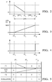
- FIG. 2 is a plot of evolution of an inlet fluid communication of the equipment of FIG. 1 as a function of pressure.
- FIG. 3 is a plot of evolution of the volume of a high pressure space of the equipment of FIG. 1 as a function of pressure.
- FIG. 4 is a plot of evolution of a return fluid communication of the equipment of FIG. 1 as a function of pressure.
- FIG. 5 is a table summarizing the domain in which regulation of the pressure in the high pressure space occurs for the equipment of FIG. 1 .
- FIGS. 6 and 7 are axial sections of a pump as per a preferred embodiment of the invention, FIG. 6 representing the pump in BDT and FIG. 7 in TDC.
- FIGS. 8 to 11 are magnified area of the pump of FIGS. 6 and 7 , the figures illustrating different phase of operation of a regulation unit of the pump.
- FIG. 12 to 15 are further details of a spool valve member of the regulation unit of the pump of FIGS. 6 to 11 .
- a self-regulated high pressure pump assembly 10 adapted to be arranged in fluid communication in an injection fuel equipment, not represented.
- a low pressure system comprising a low pressure fuel tank 12 and a transfer pump
- a high pressure system for storing and delivering the pressurized fuel, said system typically comprising a high pressure reservoir, often referred as a “common rail” to which are fluidly connected a plurality of fuel injectors.
- FIG. 1 The general hydraulic diagram of FIG. 1 enables to schematically identify the functions fulfilled by the self-regulated pump 10 and its components.
- the pump 10 has a pump body 14 provided with a pump inlet 16 and a pump outlet 18 and, between said inlet and outlet, are arranged a regulation unit 20 and a pressurizing unit 22 .
- the pressurizing unit 22 comprises a bore 24 in which a plunger 26 , forming piston, is adapted to reciprocal translations along a pumping axis X performing therein a pumping cycle between a bottom dead centre (BDC) position and a top dead centre (TDC) position.
- a compression chamber 28 which inner volume is varied during said pumping cycle, is defined between an end of the bore 24 and the piston 26 .
- Said controlled channel 34 opens in a final outlet channel 38 extending toward the pump outlet 18 adapted to be connected to a pipe, not represented, connecting to the high pressure reservoir.
- Said final outlet channel 38 is part of a high pressure space HPS comprising the high pressure reservoir, the connecting pipe and this final outlet channel 38 integral to the pump body 14 .
- Both inlet and outlet valves 32 , 36 are non-return check valves wherein a ball, or alternatively other known type of valve member, biased by a coil spring in abutment against a seating face close an orifice.
- the coil spring have low stiffness limited to maintaining the ball in closed position against their seating face when the ball is not subject to any counter force.
- the two check-valves 32 , 36 are arranged to allow fuel flow in a one-way direction globally from the inlet 16 to the outlet 18 and, to forbid counter flow. Between the lateral face of the piston 26 and the bore 24 is kept a functional clearance through which, in use, fuel leaks from the compression chamber 28 , said leaks being collected into a return leak channel 40 flowing back toward the pump inlet 16 .
- the regulation unit 20 is arranged in the pump body 14 in fluid communication between the pump inlet 16 and controlled inlet channel 30 . It aims at regulating the pressure in the high pressure space HPS by fulfilling functions further detailed afterward.
- Said regulation unit 20 takes the form of a mechanically regulated valve 42 , represented on the FIGS. 6 to 11 , having a spool valve member 44 slidably adjusted in a valve bore 46 and therein adapted to translate between a first extreme position P 1 and, a second extreme position P 2 .
- the spool valve member 44 is urged toward the first extreme position P 1 by a valve spring 48 pushing on an inlet end 50 of the spool member, FIG. 8 , and, in the opposite direction the spool 44 is urged toward the second extreme position P 2 , FIG. 11 , by the pressure in the final outlet channel 38 , some pressurized fuel being deviated from said final channel 38 to push onto an outlet end 52 of the spool member.
- the first PT 1 and second PT 2 pressure thresholds define an operational pressure range OPR of the regulation unit 20 . Conclusive tests have been conducted where said range OPR extended between 50 and 100 bars.
- the regulation unit 20 controls the pressure in the high pressure space HPS by controlling an inlet fluid communication F 1 enabling access of inlet fuel to the compression chamber 28 .
- an inlet aperture 54 is defined as the opening controlled inlet channel 30 into the valve bore 46 .
- the movements of the spool member 44 restrict said inlet fluid communication F 1 by partially closing said inlet aperture 54 from a non-restricted state or, fully open state, when the spool member 44 is in the first extreme position P 1 to, a closed state forbidding any entry of fuel into the compression chamber 28 when the spool member 44 reaches an intermediate position Pi, the pressure in the high pressure space HPS being at an intermediate pressure threshold PTi inferior to the second threshold PT 2 . Above said intermediate position Pi the inlet fluid communication F 1 remains closed.
- FIG. 1 the spool member 44 is divided in four cells referenced from right to left C 1 to C 4 .
- This first function is sketched in FIG. 1 by the four cells where in cell C 1 the inlet is fully open, in the second cell C 2 the inlet is limited, while it is fully closed in the third cell C 3 and remains closed to the final cell C 4 .
- FIG. 2 illustrates this first function. It is an X-Y graph plotting the evolution of the inlet fluid communication F 1 controlling the inlet quantity of fuel admitted in the compression chamber as a function of the pressure in the high pressure space HPS.
- the inlet fluid communication F 1 fully closes and no more fuel is admitted the compression chamber, this state being symbolized on the Y axis by number “0”. Considering the embodiment detailed below, said closure of the first fluid communication F 1 is indeed limited to some fuel leakages.
- the regulation unit 20 further controls the pressure in the high pressure space HPS by increasing the volume of said high pressure space HPS in opening a second fluid communication F 2 to a relief chamber 56 which inner volume adds up to the volume of the high pressure space HPS.
- the regulation unit 20 further controls the pressure in the high pressure space HPS since, the volume of said relief chamber 56 permanently self-adapts to the pressure in the final outlet channel 38 , the volume of the relief chamber ranging from null when the second fluid communication F 2 is closed, the spool member 44 being in the first extreme position P 1 to, a maximum volume when the spool 44 is in the second extreme position P 2 .
- This auto-regulation, or self-adaptation, of the volume of the high pressure space HPS to the pressure of the high pressure space HPS acts as a damper enabling to amortize pressure waves propagating in the pressurized fuel contained in the high pressure space HPS.
- FIG. 3 illustrates the second and third functions in another X-Y graph plot of the evolution of the volume of the high pressure space HPS as a function of the pressure in the high pressure space HPS.
- the second fluid communication F 2 is closed, this being symbolized by number “0” on the Y axis and, the volume of the high pressure space HPS is minimal.
- the second fluid communication F 2 is open and the volume of the relief chamber 56 regularly increases up to a maximum, “MAX” on the Y axis, when pressure in the high pressure space HPS rises to the second pressure threshold PT 2 , the spool member 44 reaching the second extreme position P 2 .
- the regulation unit 20 finally controls the pressure in the high pressure space HPS by opening a return fluid communication F 3 when the spool member 44 reaches the second extreme position P 2 .
- the regulation unit 20 further defines a spill channel 58 enabling exit of excess fuel contained in the relief chamber 56 and therefore in the high pressure space HPS. In the second extreme position P 2 said spill channel 58 is open, otherwise it is closed.
- the second, third and fourth functions are depicted on FIG. 1 throughout the cells C 1 -C 4 of the spool, the return fluid communication F 3 only opening in the final cell C 4 and, between the first C 1 and fourth C 4 cells the second fluid communication F 2 opens the high pressure space HPS to the relief chamber 56 which volumes varies and damps the pressure pulsations propagating within the pressurized fuel.
- FIG. 4 illustrates the fourth function in yet another X-Y graph plotting the evolution of the return fluid communication F 3 as a function of the pressure in the high pressure space HPS.
- the return fluid communication F 3 is closed, “0” on the Y axis and, when the pressure in the high pressure space HPS reaches the second pressure threshold PT 2 said return fluid communications F 3 opens, symbolized by number “1” on the Y axis.
- the inlet fluid communication F 1 is permanently fully open, the second fluid communication F 2 is permanently closed and the return fluid communication is also permanently closed.
- the inlet fluid communication F 1 is permanently closed, the second fluid communication F 2 is open and the volume of the relief chamber 56 is maximum and, the return fluid communication F 3 is open.
- the pressure in the high pressure space HPS is regulated by adjusting the inlet fluid communication F 1 thus adjusting the inlet flow as a function of the pressure in the high pressure space HPS, and also by increasing the volume of the relief chamber 56 also as a function of the pressure in the high pressure space HPS.
- the pressure in the high pressure space HPS When the pressure in the high pressure space HPS increases into a higher sub-range OPR 2 of the operational pressure range OPR, between the intermediate pressure threshold PTi and the second pressure threshold PT 2 , the pressure in the high pressure space HPS is regulated by closing the inlet fluid communication F 1 and jointly increasing the volume of relief chamber 56 still as a function of the pressure in the high pressure space HPS. This continuous increase in relief chamber volume pursues the pressure regulation by tending lowering said pressure when indeed said pressure continues to rise.
- the pump assembly 10 is represented in BDC in FIG. 6 and in TDC in FIG. 7 , the pressurizing unit 22 being on the bottom part of the figures while the regulation unit 20 is fixed on the top of it.
- the pressurizing unit 22 comprises a cylindrical body 60 having a large top portion and a downwardly extending narrower turret.
- the bore 24 provided in said pressurizing body 22 , extends along the pumping axis X both through the large portion and through the turret, the bore 24 opening in the upper face 62 of the pressurizing body as well as at the lower end of the turret. In the upper face 62 , the bore opens in a shallow recess forming a gallery 64 enlarging said opening of the bore.
- the top part of the plunger 26 is slidably arranged in the bore 24 while the bottom end downwardly protrudes out of the pressurizing body 60 toward an end provided with a cam follower 66 , or slider, adapted to follow the profile of a cam, not represented.
- a cam follower 66 or slider, adapted to follow the profile of a cam, not represented.
- a lip seal 68 preventing fuel leaks to exit and flow out of the pump where oil lubricates the cam area. Said leaks, as mentioned previously, downwardly flow between the plunger 26 and the bore 24 and are collected in the leak return channel 40 provided in the pressurizing body 60 that redirect in the upward direction said fuel leaks toward the pump inlet 16 .
- the leak return channel 40 comprises a lower portion in the pressurizing body 60 and an upper portion above.
- the regulation unit 20 also comprises a body 72 provided on its part with a recess defining a cylindrical lateral wall 74 and a bottom face 76 , said recess being complementary adjusted to receive the pressurizing body 60 which is engaged and fixed in said recess.
- the upper face 62 of the pressurizing body is sealingly compressed against the bottom face 76 of the recess and, the lateral male cylindrical face of the pressurizing body lies against the lateral female inner face of the wall 74 .
- Fixation of the bodies 60 , 72 can be done by welding or screwing, provided that complementary threads are provided on the male and female cylindrical faces of the bodies.
- the pump body 14 is the integral assembly of the pressurizing body 60 and of the regulation body 72 .
- the central area of the bottom face 76 of the recess, area that is right above the top opening of the bore 24 and above the gallery 64 forms a ceiling 78 for the compression chamber 28 .
- the peripheral area surrounding said ceiling 78 is compressed in surface contact against the complementary peripheral area of the upper face 62 of the pressurizing body ensuring sealing of the area.
- the regulation body 72 is further provided, in its upper region, with the valve bore 46 and with the final outlet channel 38 that are horizontally aligned, the valve bore 46 opening on the lateral outer face of the body 72 , right of the figure, and the final outlet channel 38 opening at the opposite, left of the figure.
- the second fluid communication F 2 takes the form of an opening 80 joining the right end of the final outlet channel 38 to left end of the valve bore 46 .
- said opening, or relief opening 80 is surrounded by a seating face 82 that can be rounded or conical and which is provided on the side of the valve bore 46 .
- the regulating body 72 is further provided with the controlled inlet channel 30 , right of the figure, and with the controlled outlet channel 34 , left of the figure, that are both vertically upwardly extend from the ceiling 78 of the compression chamber.
- the controlled inlet channel 30 opens in the valve bore 46 through the inlet aperture 54 that joins the top end of the controlled inlet channel 30 to the horizontal lateral face of the valve bore 46 .
- the inlet aperture 54 is surrounded by the seating face previously mentioned when describing the non-return inlet check valve 32 .
- said inlet valve 32 which ball is upwardly biased by the inlet valve coil spring against said seating face, thus closing the inlet aperture 54 .
- An annular member, press-fitted in the lower region of the controlled inlet channel 30 forms an annular shoulder face against which the bottom end of the spring can bear and be compressed.
- the controlled outlet channel 34 opens in the final outlet channel 38 , via an aperture 84 that vertically joins the top end of the controlled outlet channel 34 to the horizontal lateral face of the final outlet channel 38 .
- said outlet valve 36 which ball is downwardly biased by the outlet valve coil spring against a seating face provided with another annular member press-fitted in the lower region of the controlled outlet channel 34 .
- the upper end outlet valve coil spring bears against a washer member forming another annular shoulder face against which said spring is compressed.
- the arrangement of the inlet 32 and outlet 36 check valves is done to only enable fuel flow from the inlet toward the compression chamber and, from said compression chamber toward the outlet. The reverse flow is prevented by the check valves.
- the two coil springs have low stiffness just enabling to maintain the ball in place against their seating face but, as soon as fuel pushes the ball in the opening direction, said pushing force overcomes the spring force that further compresses, opening said fuel passage.
- valve bore 46 is slidably arranged the spool valve member 44 provided on its outlet end 52 , left end on the figure, with a ball 86 forming a closing member adapted to sealingly bear against the seating face 82 , thus closing the second fluid communication F 2 .
- the valve spring 48 pushes the spool member 44 in said closing position of the second fluid communication F 2 .
- the valve spring 48 is compressed between said inlet end 50 of the spool member 44 and an annular member 88 press-fitted in an inlet pipe 90 connected to the pump inlet 16 .
- the upper portion of the leak return channel 40 extends in the regulation body 72 from a connection in the lower portion to an outer opening arranged of the pump inlet opening within this inlet pipe 90 . Therefore, fuel leakage during operation flows from the compression chamber around the plunger 26 , then it reaches the return leak channel 40 prior to exit in the inlet pipe 90 where said leaks merges with the low pressure fuel inlet entering the pump.
- the regulation body 72 is further provided with a tubular outlet connection member 92 fixed around the pump outlet 18 at the opening end, left end of the figure, of the final outlet channel 38 .
- the connection member 92 is threaded to enable tightening of the connecting pipe, not represented that, along with the high pressure reservoir is part of the high pressure space HPS.
- the regulating valve 42 and the spool member 44 are now further described in reference to the FIGS. 8 to 11 .
- the spool member 44 is a cylindrical member horizontally adjusted to slide within the valve bore 46 .
- the opening end of the bore 46 in the peripheral face of the regulation body 72 is slightly enlarged, the leak return channel 40 opening in said enlarged entry 94 , further motivation for having said enlarged entry 94 of the bore being explained afterward.
- the spool member 44 extends from its inlet end 50 , right end of the figure, to its outlet end 52 , left end, wherein is crimped the ball 86 forming the closing member of the second fluid communication F 2 .
- the spool member 44 is further provided with a surrounding annular inlet groove 96 opening in the outer cylindrical face of the spool.
- the spool member 44 is further provided with an inner inlet channel 98 extending from the inlet end 50 of the spool member to an opening provided in a side face of the inlet groove 96 .
- the spill channel 58 is arranged within the spool member 44 , opening in the outlet end 52 , beside the ball 86 , and extending to a rear end opening 100 that is arranged in the cylindrical peripheral face of the spool member, in the close vicinity to the inlet end 50 .
- said spill channel 58 comprises a front portion that surrounds the ball 86 , then a straight axial portion and finally a radial portion leading to said rear end opening 100 .
- the inner inlet channel 98 could only comprise one straight portion drilled angularly from the rear end opening 100 to the outlet end 52 of the spool member.
- FIG. 8 illustrates the first function of the regulation unit 20 , where the pressure in the high pressure space HPS is below the first pressure threshold PT 1 , the spool member 44 being in the first extreme position P 1 , the inlet fluid communication F 1 is fully open, the second fluid communication F 2 and the outlet fluid communication F 3 are closed.
- the inlet aperture 54 opens in the inlet groove 96 and the fuel flowing from the inlet pipe 90 to the compression chamber 28 has a non-restricted path, this is represented on the figure by the large arrow A 1 .
- Said fuel easily flows in the inner inlet channel 98 then, in the inlet groove 96 , it passes the inlet aperture 54 easily pushing the ball of the inlet valve 32 to flow in the controlled inlet channel 30 prior to entering the compression chamber 28 .
- An advantage for having the inlet groove 96 over a simple radial opening is that whatever is the angular position of the spool member 44 in the valve bore, the inlet aperture 54 always opens in said inlet groove. Consequently angular positioning of the spool member relative to the valve bore is not required.
- the pressure in the high pressure space HPS is not regulated, all parameters being constant.
- FIG. 9 illustrates the second function of the regulation unit 20 , where the pressure in the high pressure space HPS is superior to the first pressure threshold PT 1 , within the lower sub-range OPR 1 , the inlet fluid communication F 1 is restricted, the second fluid communication F 2 is open and the outlet fluid communication F 3 is closed.
- the pressure in the high pressure space HPS is regulated by the addition of the volume of the relief chamber to the high pressure space HPS and also by, the restriction of the inlet flow. Both said addition and said restriction are continuous function dependent upon the pressure in the high pressure space HPS.
- FIG. 10 illustrates the third function of the regulation unit 20 , where the pressure in the high pressure space HPS has reached the intermediate pressure threshold PTi, the inlet fluid communication F 1 is closed, the second fluid communication F 2 is open and the outlet fluid communication F 3 is closed.
- the pressure in the high pressure space HPS is regulated by the further continuous addition of the volume of the relief chamber to the high pressure space HPS and, by closing the inlet flow.
- FIG. 11 illustrates the fourth function of the regulation unit 20 , where the pressure in the high pressure space HPS has reached the second pressure threshold PT 2 , the inlet fluid communication F 1 remains closed, the second fluid communication F 2 is open and the outlet fluid communication F 3 is now open.
- the spool member 44 of the described embodiment is further presented in the FIGS. 12 to 15 enabling to visualize the inner inlet channel 98 , the spill channel 56 , the ball 86 , the outer cylindrical face and the inlet groove 96 .
- the rear opening 100 of the spill channel indeed opens in a spill groove 102 provided in the spool member
- said inlet end 50 is provided with a protrusion 104 around which the last turns of the valve spring 48 engage.
Landscapes
- Engineering & Computer Science (AREA)
- Mechanical Engineering (AREA)
- General Engineering & Computer Science (AREA)
- Chemical & Material Sciences (AREA)
- Combustion & Propulsion (AREA)
- Fuel-Injection Apparatus (AREA)
- Safety Valves (AREA)
Abstract
Description
-
- the first line is the pressure in the high pressure space HPS as it is scaled in X axis of the plots of
FIGS. 2, 3 and 4 ; - The second line is the state of the inlet fluid communication F1 as plotted in
FIG. 2 ; - the third line is the state of the second fluid communication and the volume of the
relief chamber 56 as plotted inFIG. 3 ; - the fourth line is the state of the return fluid communication F3 as plotted in
FIG. 4 and, - the bottom line is the state of regulation of the pressure in the high pressure space HPS where, outside the operational pressure range OPR there is no regulation provided since none of the parameters varies but, when return fluid communication F3 opens the actual pressure in the high pressure space HPS cannot increase any more.
- the first line is the pressure in the high pressure space HPS as it is scaled in X axis of the plots of
-
- X pumping axis
- BDC bottom dead centre
- TDC top dead centre
- P1 first extreme position
- P2 second extreme position
- Pi intermediate position
- HPS high pressure space
- PT1 first pressure threshold
- PT2 second pressure threshold
- PTi intermediate pressure threshold
- OPR operational pressure range
- OPR1 lower sub-range
- OPR2 higher sub-range
- F1 inlet fluid communication
- F2 second fluid communication
- F3 return fluid communication
- 10 pump assembly
- 12 low pressure fuel tank
- 14 pump body
- 16 pump inlet
- 18 pump outlet
- 20 regulation unit
- 22 pressurizing unit
- 24 bore
- 26 plunger—piston
- 28 compression chamber
- 30 controlled inlet channel
- 32 inlet valve
- 34 controlled outlet channel
- 36 outlet valve
- 38 final outlet channel
- 40 leak return channel
- 42 mechanically regulated valve
- 44 spool valve member
- 46 valve bore
- 48 valve spring
- 50 inlet end of the spool member
- 52 outlet end of the spool member
- 54 inlet aperture
- 56 relief chamber
- 58 spill channel
- 60 pressurizing body
- 62 upper face of the pressurizing body
- 64 gallery
- 66 cam follower
- 68 lip seal
- 70 main valve spring
- 72 regulation body
- 74 cylindrical lateral wall
- 76 bottom face
- 78 ceiling of the compression chamber
- 80 opening—relief opening
- 82 seating face
- 84 aperture of the controlled outel channel
- 86 ball—closing member of the spool
- 88 annular member
- 90 inlet pipe
- 92 outlet connection member
- 94 enlarged entry of the bore
- 96 inlet groove
- 98 inner inlet channel
- 100 rear opening of the spill channel
- 102 spill groove
- 104 protrusion
Claims (16)
Applications Claiming Priority (3)
| Application Number | Priority Date | Filing Date | Title |
|---|---|---|---|
| GB1608141.6A GB2550144A (en) | 2016-05-10 | 2016-05-10 | Fuel pump |
| GB1608141.6 | 2016-05-10 | ||
| PCT/EP2017/060723 WO2017194389A1 (en) | 2016-05-10 | 2017-05-04 | Fuel pump |
Publications (2)
| Publication Number | Publication Date |
|---|---|
| US20190145365A1 US20190145365A1 (en) | 2019-05-16 |
| US10648437B2 true US10648437B2 (en) | 2020-05-12 |
Family
ID=56297422
Family Applications (1)
| Application Number | Title | Priority Date | Filing Date |
|---|---|---|---|
| US16/300,343 Active US10648437B2 (en) | 2016-05-10 | 2017-05-04 | Fuel pump |
Country Status (5)
| Country | Link |
|---|---|
| US (1) | US10648437B2 (en) |
| EP (1) | EP3455486B1 (en) |
| CN (1) | CN109416010B (en) |
| GB (1) | GB2550144A (en) |
| WO (1) | WO2017194389A1 (en) |
Families Citing this family (6)
| Publication number | Priority date | Publication date | Assignee | Title |
|---|---|---|---|---|
| DE102015215186B3 (en) | 2015-08-10 | 2016-12-15 | Continental Automotive Gmbh | High-pressure fuel pump |
| US10871136B2 (en) * | 2018-07-05 | 2020-12-22 | Delphi Technologies Ip Limited | Fuel pump and inlet valve assembly thereof |
| CN113464397A (en) * | 2020-03-30 | 2021-10-01 | 福爱电子(贵州)有限公司 | Double-pulse pump liquid injection device |
| US11660626B2 (en) * | 2020-10-06 | 2023-05-30 | Bell Sports, Inc. | Reciprocal pumps |
| CN116591924B (en) * | 2023-05-11 | 2025-12-16 | 浙江大学 | Active pressure compensator for deep sea sampling and pressure compensation method thereof |
| GB2640114A (en) * | 2023-12-21 | 2025-10-15 | Combined Pumps Corp Ltd | Check valve arrangement for a transfer pump and a method of using the same |
Citations (11)
| Publication number | Priority date | Publication date | Assignee | Title |
|---|---|---|---|---|
| US6176225B1 (en) * | 1998-06-05 | 2001-01-23 | Avl List Gmbh | Injection system |
| DE102007022219A1 (en) | 2007-05-11 | 2008-11-13 | Robert Bosch Gmbh | Fuel system comprises fuel pump linked to fuel source that includes adjustment system |
| US20090097997A1 (en) | 2007-10-12 | 2009-04-16 | Nippon Soken, Inc. | Fuel pump |
| JP2010163888A (en) | 2009-01-13 | 2010-07-29 | Toyota Motor Corp | Fuel supply device for internal combustion engine |
| US20110000182A1 (en) * | 2002-11-01 | 2011-01-06 | George Lasker | Uncoupled, thermal-compressor, gas-turbine engine |
| US20110114064A1 (en) | 2007-11-16 | 2011-05-19 | Toyota Jidosha Kabushiki Kaisha | High-pressure fuel supply apparatus for internal combustion engine |
| US20110125387A1 (en) | 2009-11-26 | 2011-05-26 | Denso Corporation | Fuel supply system having pressure control valve |
| US20120118053A1 (en) * | 2010-11-10 | 2012-05-17 | Gabriele Serra | Method for determining the injection law of a fuel injector |
| US20120123703A1 (en) * | 2010-11-10 | 2012-05-17 | Gabriele Serra | Method for determining the injection law of a fuel injector using a roller-test bench |
| WO2012089511A1 (en) | 2010-12-27 | 2012-07-05 | Robert Bosch Gmbh | Pressure control arrangement of a fuel injection system having a valve which is arranged on the pressure side of a pump |
| US10385795B2 (en) * | 2016-05-31 | 2019-08-20 | Ford Global Technologies, Llc | Fuel tank pressure sensor rationality testing using V2X technology |
-
2016
- 2016-05-10 GB GB1608141.6A patent/GB2550144A/en not_active Withdrawn
-
2017
- 2017-05-04 EP EP17723964.7A patent/EP3455486B1/en active Active
- 2017-05-04 CN CN201780037877.XA patent/CN109416010B/en not_active Expired - Fee Related
- 2017-05-04 WO PCT/EP2017/060723 patent/WO2017194389A1/en not_active Ceased
- 2017-05-04 US US16/300,343 patent/US10648437B2/en active Active
Patent Citations (11)
| Publication number | Priority date | Publication date | Assignee | Title |
|---|---|---|---|---|
| US6176225B1 (en) * | 1998-06-05 | 2001-01-23 | Avl List Gmbh | Injection system |
| US20110000182A1 (en) * | 2002-11-01 | 2011-01-06 | George Lasker | Uncoupled, thermal-compressor, gas-turbine engine |
| DE102007022219A1 (en) | 2007-05-11 | 2008-11-13 | Robert Bosch Gmbh | Fuel system comprises fuel pump linked to fuel source that includes adjustment system |
| US20090097997A1 (en) | 2007-10-12 | 2009-04-16 | Nippon Soken, Inc. | Fuel pump |
| US20110114064A1 (en) | 2007-11-16 | 2011-05-19 | Toyota Jidosha Kabushiki Kaisha | High-pressure fuel supply apparatus for internal combustion engine |
| JP2010163888A (en) | 2009-01-13 | 2010-07-29 | Toyota Motor Corp | Fuel supply device for internal combustion engine |
| US20110125387A1 (en) | 2009-11-26 | 2011-05-26 | Denso Corporation | Fuel supply system having pressure control valve |
| US20120118053A1 (en) * | 2010-11-10 | 2012-05-17 | Gabriele Serra | Method for determining the injection law of a fuel injector |
| US20120123703A1 (en) * | 2010-11-10 | 2012-05-17 | Gabriele Serra | Method for determining the injection law of a fuel injector using a roller-test bench |
| WO2012089511A1 (en) | 2010-12-27 | 2012-07-05 | Robert Bosch Gmbh | Pressure control arrangement of a fuel injection system having a valve which is arranged on the pressure side of a pump |
| US10385795B2 (en) * | 2016-05-31 | 2019-08-20 | Ford Global Technologies, Llc | Fuel tank pressure sensor rationality testing using V2X technology |
Also Published As
| Publication number | Publication date |
|---|---|
| GB201608141D0 (en) | 2016-06-22 |
| GB2550144A (en) | 2017-11-15 |
| CN109416010B (en) | 2021-03-19 |
| EP3455486B1 (en) | 2020-04-08 |
| US20190145365A1 (en) | 2019-05-16 |
| CN109416010A (en) | 2019-03-01 |
| WO2017194389A1 (en) | 2017-11-16 |
| EP3455486A1 (en) | 2019-03-20 |
| GB2550144A8 (en) | 2018-01-24 |
Similar Documents
| Publication | Publication Date | Title |
|---|---|---|
| US10648437B2 (en) | Fuel pump | |
| US10941741B2 (en) | High-pressure fuel supply pump | |
| US7690588B2 (en) | Fuel injector nozzle with flow restricting device | |
| US20080056914A1 (en) | High-Pressure Fuel Supply Pump | |
| JP4940329B2 (en) | High pressure fuel supply pump | |
| US10865718B2 (en) | Pressure regulating modules with controlled leak paths | |
| EP3135900B1 (en) | High-pressure fuel supply pump | |
| US20160153366A1 (en) | Pump Arrangement And System For A Motor Vehicle | |
| US11002236B2 (en) | High-pressure fuel supply pump | |
| KR20140147101A (en) | Flow restrictor with ball and throttle | |
| JP6934519B2 (en) | High pressure fuel pump | |
| US12006901B2 (en) | Fuel pump | |
| JP2010071266A (en) | High-pressure fuel supply system | |
| JP2005140071A (en) | Piezoelectric element driven three-way selector valve and fuel injection valve using the same | |
| US20200284229A1 (en) | High-pressure fuel supply pump | |
| JP2020133490A (en) | High-pressure fuel supply pump and relief valve mechanism | |
| JP2019090365A (en) | Fuel supply pump | |
| JP6817117B2 (en) | Relief valve mechanism and fuel supply pump equipped with it | |
| JP7089399B2 (en) | Manufacturing method of fuel supply pump and fuel supply pump | |
| US20240151198A1 (en) | Fuel Pump | |
| WO2015124340A1 (en) | Fuel injector | |
| GB2544974A (en) | An accumulator for use in a fuel line to attenuate pressure peaks |
Legal Events
| Date | Code | Title | Description |
|---|---|---|---|
| FEPP | Fee payment procedure |
Free format text: ENTITY STATUS SET TO UNDISCOUNTED (ORIGINAL EVENT CODE: BIG.); ENTITY STATUS OF PATENT OWNER: LARGE ENTITY |
|
| AS | Assignment |
Owner name: DELPHI AUTOMOTIVE SYSTEMS LUXEMBOURG SA, LUXEMBOUR Free format text: NUNC PRO TUNC ASSIGNMENT;ASSIGNORS:LEBLAY, ARNAUD;BOSSI, ADRIEN;HOFFMANN, GUY;REEL/FRAME:049035/0353 Effective date: 20181115 Owner name: DELPHI AUTOMOTIVE SYSTEMS LUXEMBOURG SA, LUXEMBOURG Free format text: NUNC PRO TUNC ASSIGNMENT;ASSIGNORS:LEBLAY, ARNAUD;BOSSI, ADRIEN;HOFFMANN, GUY;REEL/FRAME:049035/0353 Effective date: 20181115 |
|
| STPP | Information on status: patent application and granting procedure in general |
Free format text: DOCKETED NEW CASE - READY FOR EXAMINATION |
|
| STPP | Information on status: patent application and granting procedure in general |
Free format text: NON FINAL ACTION MAILED |
|
| STPP | Information on status: patent application and granting procedure in general |
Free format text: RESPONSE TO NON-FINAL OFFICE ACTION ENTERED AND FORWARDED TO EXAMINER |
|
| STPP | Information on status: patent application and granting procedure in general |
Free format text: NOTICE OF ALLOWANCE MAILED -- APPLICATION RECEIVED IN OFFICE OF PUBLICATIONS |
|
| STCF | Information on status: patent grant |
Free format text: PATENTED CASE |
|
| AS | Assignment |
Owner name: BORGWARNER LUXEMBOURG OPERATIONS SARL, LUXEMBOURG Free format text: ASSIGNMENT OF ASSIGNORS INTEREST;ASSIGNOR:BORGWARNER LUXEMBOURG AUTOMOTIVE SYSTEMS S.A.;REEL/FRAME:064582/0015 Effective date: 20230814 Owner name: BORGWARNER LUXEMBOURG AUTOMOTIVE SYSTEMS S.A., LUXEMBOURG Free format text: CHANGE OF NAME;ASSIGNOR:DELPHI AUTOMOTIVE SYSTEMS LUXEMBOURG SA;REEL/FRAME:064586/0585 Effective date: 20230814 |
|
| MAFP | Maintenance fee payment |
Free format text: PAYMENT OF MAINTENANCE FEE, 4TH YEAR, LARGE ENTITY (ORIGINAL EVENT CODE: M1551); ENTITY STATUS OF PATENT OWNER: LARGE ENTITY Year of fee payment: 4 |
|
| AS | Assignment |
Owner name: PHINIA DELPHI LUXEMBOURG SARL, LUXEMBOURG Free format text: CHANGE OF NAME;ASSIGNOR:BORGWARNER LUXEMBOURG OPERATIONS SARL;REEL/FRAME:066550/0911 Effective date: 20230929 |
|
| AS | Assignment |
Owner name: BORGWARNER LUXEMBOURG OPERATIONS SARL, LUXEMBOURG Free format text: CORRECTIVE ASSIGNMENT TO CORRECT THE CORRECTIVE ASSIGNMENT TO CORRECT THE EXECUTION DATE ON PAGE 1 PREVIOUSLY RECORDED ON REEL 64582 FRAME 15. ASSIGNOR(S) HEREBY CONFIRMS THE ASSIGNMENT OF RIGHTS. PREVIOUSLY RECORDED ON REEL 64582 FRAME 15. ASSIGNOR(S) HEREBY CONFIRMS THE ASSIGNMENT OF RIGHTS;ASSIGNOR:BORGWARNER LUXEMBOURG AUTOMOTIVE SYSTEMS S.A.;REEL/FRAME:066945/0922 Effective date: 20230601 Owner name: BORGWARNER LUXEMBOURG AUTOMOTIVE SYSTEMS S.A., LUXEMBOURG Free format text: CORRECTIVE ASSIGNMENT TO CORRECT THE EXECUTION DATE ON PAGE 1 PREVIOUSLY RECORDED ON REEL 64586 FRAME 585. ASSIGNOR(S) HEREBY CONFIRMS THE CHANGE OF NAME;ASSIGNOR:DELPHI AUTOMOTIVE SYSTEMS LUXEMBOURG SA;REEL/FRAME:066554/0814 Effective date: 20210427 |
|
| AS | Assignment |
Owner name: PHINIA HOLDINGS JERSEY LTD, JERSEY Free format text: ASSIGNMENT OF ASSIGNORS INTEREST;ASSIGNOR:PHINIA DELPHI LUXEMBOURG SARL;REEL/FRAME:067592/0801 Effective date: 20231231 Owner name: PHINIA JERSEY HOLDINGS LLC, DELAWARE Free format text: ASSIGNMENT OF ASSIGNORS INTEREST;ASSIGNOR:PHINIA HOLDINGS JERSEY LTD;REEL/FRAME:067592/0662 Effective date: 20231231 Owner name: PHINIA JERSEY HOLDINGS LLC, DELAWARE Free format text: ASSIGNMENT OF ASSIGNOR'S INTEREST;ASSIGNOR:PHINIA HOLDINGS JERSEY LTD;REEL/FRAME:067592/0662 Effective date: 20231231 Owner name: PHINIA HOLDINGS JERSEY LTD, JERSEY Free format text: ASSIGNMENT OF ASSIGNOR'S INTEREST;ASSIGNOR:PHINIA DELPHI LUXEMBOURG SARL;REEL/FRAME:067592/0801 Effective date: 20231231 |
|
| AS | Assignment |
Owner name: U.S. BANK TRUST COMPANY, NATIONAL ASSOCIATION, MICHIGAN Free format text: SECURITY INTEREST;ASSIGNOR:PHINIA JERSEY HOLDINGS LLC;REEL/FRAME:068324/0658 Effective date: 20240801 Owner name: BANK OF AMERICA, N.A., NORTH CAROLINA Free format text: SECURITY INTEREST;ASSIGNOR:PHINIA JERSEY HOLDINGS LLC;REEL/FRAME:068324/0623 Effective date: 20240801 |