US10645002B2 - System, apparatus and method for managing redundancy elimination in packet storage during observation of data movement - Google Patents
System, apparatus and method for managing redundancy elimination in packet storage during observation of data movement Download PDFInfo
- Publication number
- US10645002B2 US10645002B2 US14/743,902 US201514743902A US10645002B2 US 10645002 B2 US10645002 B2 US 10645002B2 US 201514743902 A US201514743902 A US 201514743902A US 10645002 B2 US10645002 B2 US 10645002B2
- Authority
- US
- United States
- Prior art keywords
- packet
- data
- logical storage
- continuous logical
- content
- Prior art date
- Legal status (The legal status is an assumption and is not a legal conclusion. Google has not performed a legal analysis and makes no representation as to the accuracy of the status listed.)
- Active
Links
Images


Classifications
-
- H—ELECTRICITY
- H04—ELECTRIC COMMUNICATION TECHNIQUE
- H04L—TRANSMISSION OF DIGITAL INFORMATION, e.g. TELEGRAPHIC COMMUNICATION
- H04L45/00—Routing or path finding of packets in data switching networks
- H04L45/74—Address processing for routing
-
- H—ELECTRICITY
- H04—ELECTRIC COMMUNICATION TECHNIQUE
- H04L—TRANSMISSION OF DIGITAL INFORMATION, e.g. TELEGRAPHIC COMMUNICATION
- H04L45/00—Routing or path finding of packets in data switching networks
- H04L45/74—Address processing for routing
- H04L45/742—Route cache; Operation thereof
-
- H—ELECTRICITY
- H04—ELECTRIC COMMUNICATION TECHNIQUE
- H04L—TRANSMISSION OF DIGITAL INFORMATION, e.g. TELEGRAPHIC COMMUNICATION
- H04L45/00—Routing or path finding of packets in data switching networks
- H04L45/74—Address processing for routing
- H04L45/745—Address table lookup; Address filtering
- H04L45/7453—Address table lookup; Address filtering using hashing
Definitions
- Embodiments of the disclosure relate to the field of data storage for network and cyber security systems. More specifically, one embodiment of the disclosure relates to a system, apparatus and method for managing redundancy elimination through configuration of a layered storage architecture that supports bounded deduplication references and controlled management of the data cache.
- malware malicious software
- Malware has many forms including exploits, namely information that attempts to take advantage of a vulnerability in software that is loaded onto an electronic device in order to adversely influence or attack operations of that electronic device.
- exploits namely information that attempts to take advantage of a vulnerability in software that is loaded onto an electronic device in order to adversely influence or attack operations of that electronic device.
- malware continues to evade and infect electronic devices worldwide.
- packet storage is limited, and thus, as storage reaches capacity, old data would need to be removed (purged) and new data would need to be written into storage.
- the stored reference for new data may refer to some purged data. This will render the newly written data useless since portions of the new data will be missing.
- a chain of references may cause significant delays in packet retrieval. For instance, when a specific packet is retrieved from the packet store, cascaded references of packets could lead to reconstruction of one or more packets resulting in retrieval of the whole cascaded chain.
- a reference in packet B may refer to the same data within packet A and another reference in packet C may refer to the reference in packet B.
- the retrieval of packet C will implicitly result in retrieval of packet B and as well packet A, where these ancillary retrievals may unnecessary increase load on packet processing capabilities and increase the delay in retrieving packet C.
- FIG. 1 is an exemplary block diagram of a logical storage architecture that is configured in the management of redundancy elimination and data (dedup) cache storage.
- FIG. 2 is an exemplary block diagram of a communication system deploying a multi-tier security framework.
- FIG. 3A is an exemplary block diagram of the security framework of FIG. 2 .
- FIG. 3B is a general block diagram of the interoperability of a management system and the security framework of FIG. 2 .
- FIG. 4A is an exemplary embodiment of a logical representative of the network sensor engine of FIGS. 3A-3B .
- FIG. 4B is another exemplary embodiment of the network sensor engine of FIGS. 3A-3B .
- FIG. 5 is an exemplary embodiment of storage allocation conducted by the cache management logic implemented within the network sensor engine of FIG. 4 for generation of “bounded” deduplication references.
- FIG. 6 is an exemplary block diagram of a logical storage layout for a StorBlock.
- FIG. 7 is an exemplary embodiment of a flowchart directed to redundancy elimination operations conducted by the storage management logic of FIG. 4A .
- FIG. 8 is an illustrative example of redundancy elimination operations, in particular deduplication operations, as described in FIG. 7 .
- FIGS. 9A and 9B are logical representations of data (dedup) cache management.
- FIG. 10 is an exemplary block diagram of an “aged” bloom filter scheme conducted during data cache management by the cache management logic of FIG. 4A .
- FIG. 11 is an exemplary block diagram of an “aged” bloom filter scheme with enhanced redundancy that is conducted during data cache management by the cache management logic of FIG. 4A .
- Various embodiments of the disclosure relate to a network sensor engine that manages deduplication through configuration of a layered storage architecture that supports “bounded” deduplication references and manages data (dedup) cache storage. Such management is adapted to increase storage efficiency at the data cache while keeping the size of the cache manageable and mitigating retrieval latency and potential data loss.
- redundancy elimination may be achieved through management of deduplication in packet storage by constraining the deduplication references so that a “bounded” deduplication reference may refer only to stored content within the same contiguous, logical storage area.
- This contiguous, logical storage area referred to herein as a “StorBlock,” is a hardware abstract for mapping content into non-transitory storage medium.
- Redundancy elimination may be further achieved through management of the data (dedup) cache, where “active” content-based hash values (e.g., rolling hash values associated with detected duplicated content) populate the data cache under control of a first level content analysis device while representative data for “inactive” content-based hash values is maintained within a data store.
- active content-based hash values e.g., rolling hash values associated with detected duplicated content
- one or more contiguous, logical storage areas operate as a hardware abstraction for storage logic, which represents logical storage (e.g., a volume or logical drive) and/or physical storage.
- the storage logic may correspond to one or more hard disk drives and each StorBlock may correspond to a prescribed region or regions of the hard disk drive(s), a Redundant Array of Independent Disks (RAID) type storage, or storage over a network such as Network File System (NFS) or Internet Small Computer System Interface (iSCSI).
- NFS Network File System
- iSCSI Internet Small Computer System Interface
- each bounded deduplication reference is permitted to refer to data within the same StorBlock.
- bounded deduplication references are not permitted to access data within a different StorBlock (i.e., the deduplication reference does not cross a StorBlock).
- the deduplication reference does not cross a StorBlock.
- a StorBlock is configurable, based on two opposing factors: storage efficiency and data loss mitigation. For instance, larger StorBlocks may support more deduplication references, which may improve the overall storage efficiency of the network sensor engine. Furthermore, any loss of data in a StorBlock could cause loss of the whole StorBlock. Hence, where the StorBlock is smaller is size, there is a greater likelihood that a greater amount of packet data will be accessible for incident response testing and improved network breach detection.
- Data cache management involves prioritizing and controlling storage of content-based hash values associated with duplicated content in order to ensure retention of content that may be useful in subsequent malware analysis.
- storage management logic within the network sensor engine includes a first level content analysis device operating as part of the cache management logic, where the first level content analysis device is adapted to determine whether content with a packet under analysis, represented by a content-based hash value, has been previously stored within a StorBlock to which the packet under analysis has been allocated.
- the first level content analysis device uses a lesser amount of memory resources than the data cache supporting the same number of content-based hash values.
- a bloom filter may be deployed as the first level content analysis device.
- the first level content analysis device when deployed as a bloom filter, is not adapted to store content-based hash values per se. Rather, the bloom filter is configured to identify whether input data (e.g., content-based hash value) has been detected previously, and similarly, may identify whether the content-based hash value has possibly been analyzed previously, where a few false positives may occur depending on the size of the bit array used for the bloom filter.
- the bloom filter stores values derived from the content-based hash values as part of the analyzed “set” with a data store, but such storage requires significant less memory than the hash values themselves.
- an “aged” bloom filter may provide further storage savings through removal of less actively accessed content-based has values, as illustrated in FIG. 10 .
- a sensor may include circuitry having data processing and/or data capturing functionality combined with data transmission and/or storage functionality.
- a sensor may include a processor (e.g., digital signal processor, microprocessor with one or more processor cores, a programmable gate array, a microcontroller, an application specific integrated circuit, etc.), semiconductor memory, and/or wireless or wired transmitter and/or transceiver circuitry.
- the senor may be software in the form of one or more software images or software modules, such as executable code in the form of an executable application, an application programming interface (API), a routine or subroutine, a script, a procedure, an applet, a servlet, source code, object code, a shared library/dynamic load library, or one or more instructions.
- the software module(s) may be stored in any type of a suitable non-transitory storage medium, or transitory storage medium (e.g., electrical, optical, acoustical or other form of propagated signals such as carrier waves, infrared signals, or digital signals).
- non-transitory storage medium may include, but are not limited or restricted to a programmable circuit; a semiconductor memory; non-persistent storage such as volatile memory (e.g., any type of random access memory “RAM”); persistent storage such as non-volatile memory (e.g., read-only memory “ROM”, power-backed RAM, flash memory, phase-change memory, etc.), a solid-state drive, hard disk drive, an optical disc drive, or a portable memory device.
- volatile memory e.g., any type of random access memory “RAM”
- persistent storage such as non-volatile memory (e.g., read-only memory “ROM”, power-backed RAM, flash memory, phase-change memory, etc.), a solid-state drive, hard disk drive, an optical disc drive, or a portable memory device.
- firmware the executable code is stored in persistent storage.
- data and content are broadly defined as information, normally in digitized form. Hence, data and content may include control information or management information.
- traffic generally refers to one or more flows of information, where each “flow” may be a series of related packets in transit.
- This series of related packets may feature one of more objects, namely a plurality of related packets operating as an executable element or a non-executable element such as a dynamically link library (DLL), a Portable Document Format (PDF) file, a JavaScript® file, Zip® file, a Flash® file, a document (for example, a Microsoft® Office® document, Word® document, etc.), an electronic mail (email), downloaded web page, a text message, or the like.
- DLL dynamically link library
- PDF Portable Document Format
- JavaScript® file e.g., a JavaScript® file
- Zip® file e.g., a Flash® file
- a document for example, a Microsoft® Office® document, Word® document, etc.
- email electronic mail
- downloaded web page a text message, or the like.
- a “packet” generally refers to
- the term “transmission medium” is a physical or logical communication path between two or more network devices (e.g., one of the network devices being an endpoint device with data processing and network connectivity such as, for example, a server; a mainframe; a firewall; intermediary devices such as a router, a switch or a bridge; or a client device such as a desktop or laptop computer, netbook, tablet, smart phone, set top box, wearable computing device, or a video game console).
- the communication path may include wired and/or wireless segments, and/or shared memory locations. Examples of wired and/or wireless segments include electrical wiring, optical fiber, cable, bus trace, or a wireless channel using infrared, radio frequency (RF), or any other wired/wireless signaling mechanism.
- RF radio frequency
- the logical storage architecture 100 includes one or more contiguous, logical storage areas (hereinafter “StorBlocks”) 110 1 - 110 M (M ⁇ 1), where each StorBlock 110 1 - 110 M is segmented into a number of prescribed regions (“SubStors”) 120 1 - 120 N (N ⁇ 1).
- StorBlocks contiguous, logical storage areas
- SubStors prescribed regions
- StorBlocks 110 1 - 110 M formulate a hardware abstraction layer that is configured to directly or indirectly map stored content to a physical storage. More specifically, on the lower layer of the logical storage architecture, an integer multiple of StorBlocks 110 1 - 110 M may map to a portion or the entire physical storage (e.g., a volume, etc.).
- the logical storage architecture 100 may be configured with four (4) StorBlocks 110 1 - 110 4 that logically map onto a two terabyte (TB) disk, where each StorBlock 110 1 , . . . , and 110 4 is assigned 512 gigabytes (GB) of memory.
- TB terabyte
- StorBlocks 110 1 - 110 M enables the scope of deduplication references to be “bounded” by restricting deduplication references to only reference storage locations within the same StorBlock and the compression dictionary references being confined to the same SubStor. By restricting the deduplication to reference data within the same StorBlock, a loss of that StorBlock will not affect data on any other StorBlocks.
- the hardware abstraction allows for adaptation to multiple platform environments including one or more virtual machines, cloud computing, purpose built hardware, or the like. Furthermore, in response to an increase in storage capacity (e.g., increase disk density), hardware abstraction does not require the layout of the storage architecture to be remodeled. Rather, the number or size of the StorBlocks 110 1 - 110 M may be increased. Also, this hardware abstraction allows for management of hard disk drives having different disks densities without altering the storage architecture.
- each StorBlock 110 1 - 110 M may be static or dynamically adjustable. It is noted that dynamic adjustment may be configured so that each StorBlock 110 1 . . . or 110 M is assigned the same amount of physical memory or different StorBlocks 110 1 . . . or 110 M may be assigned different amounts of physical memory. According to one embodiment, the size may be selected based on a ratio of redundancy elimination and the size of the physical storage (e.g., hard disks) available for access.
- the physical storage e.g., hard disks
- each StorBlock 110 1 , . . . , and 110 M may be configured as a large storage area
- management of the StorBlocks 110 1 - 110 M may be a challenge. For instance, some issues may arise from the need to write stored contents within a particular StorBlock (e.g., StorBlock 110 1 ) into multiple cores/threads of the system, to allocate memory to write one or more deduplication references and then further compress the deduplicated reference(s).
- StorBlocks 110 1 - 110 M may be segmented into smaller logical storage areas 120 1 - 120 N (also referred to herein as “SubStors”), which may have a size from one megabyte (1 MB) up to the order of tens of megabytes (e.g., 64 MB).
- SubStors 120 1 - 120 N information is managed as SubStors 120 1 - 120 N , where each of the SubStors (e.g., SubStor 120 1 ) includes a header 130 and a body 140 that includes compressed packet content 150 1 - 150 P (P ⁇ 1), namely compressed data from “P” packets associated with network traffic and/or information uploaded by one or multiple sources as described below in reference to FIGS. 3A-3B .
- information within a particular SubStor 120 1 . . . or 120 N may be stored within the physical storage (disk/volume) located within network sensor engine 300 or data analysis engine 320 of FIG. 3 .
- a prescribed threshold e.g., full, exceeds a certain percentage of capacity, etc.
- a particular SubStor 120 1 . . . or 120 N e.g., body and/or header of packets 150 1 - 150 P
- the analysis as to whether the prescribed threshold has been reached may be based on the uncompressed state or the compressed state.
- some of the factors that may decide the size of the SubStors 120 1 - 120 N and the prescribed threshold of transfer of the information to physical storage may include compression efficiency and retrieval latency.
- information may be transferred into one of the SubBlocks 110 1 - 110 M in multiple ways. For instance, information associated with one or more flows handled by a particular processor thread can be routed to a selected SubBlock (e.g., SubBlock 110 1 ). Thus, management of the SubBlock 110 1 can be conducted without any synchronization, and when SubBlock 110 1 reaches the prescribed threshold, the information stored within SubBlock 110 1 may be pushed to the physical storage. As another option, all encrypted flows or flows using a specific certificate can be routed to a specific SubBlock (e.g., SubBlock 110 2 ) without waiting for keys.
- a specific SubBlock e.g., SubBlock 110 2
- the search overhead to decrypt the data for a flow greatly reduces, when a certificate is provided at some later point after the capture.
- information is transferred based on policy, where packets from specific hosts (e.g., packets from an endpoint device controlled by a high-level official or executive) can be redirected to a specific SubBlock (e.g., SubBlock 110 3 ).
- a specific SubBlock e.g., SubBlock 110 3
- FIG. 2 an exemplary block diagram of a communication system 200 deploying a multi-tier security framework 210 is shown.
- the security framework 210 monitors and analyzes information associated with network traffic 220 that is routed over transmission medium 230 forming an enterprise network 240 .
- the security framework 210 receives, processes and/or stores input information associated with communications occurring within the enterprise network 240 .
- the security framework 210 may be communicatively coupled with the transmission medium 230 via a network interface 250 .
- the network interface 250 operates as a data capturing device (sometimes referred to as a “tap” or “network tap”) that is configured to receive information propagating to/from one or more endpoint devices 270 and provide at least some of this information to the security framework 210 .
- the network interface 250 may provide a series of packets or certain content within the packets.
- input information from the network interface 250 may be duplicative of information previously detected over transmission medium 230 .
- the security framework 210 may be positioned in-line with the endpoint device(s) 270 without the network interface 250 .
- the network interface 250 may be part of the security framework 210 .
- the input information may include information associated with one or more messages forming incoming network traffic received via a communication network 260 .
- the communication network 260 may include a public network (e.g., Internet) in which case one or more security appliances, such as a firewall for example, are positioned to receive and process network traffic prior to receipt by logic within the security framework 210 .
- the communication network 260 may be a private network such as a wireless data telecommunication network, wide area network (WAN), a type of local area network (LAN), or a combination of networks.
- the input information may include log information, one or more flow based collections such as netflow (e.g., OSI Layer 4 “L4” information regarding communications monitored by other network devices), and host telemetry information (e.g., information from endpoint devices 270 ), as described below.
- netflow e.g., OSI Layer 4 “L4” information regarding communications monitored by other network devices
- host telemetry information e.g., information from endpoint devices 270
- FIG. 2 illustrates the multi-tier security framework 210 within the enterprise network 240
- the multi-tier security framework 210 is at least partially located outside the enterprise network 240 .
- at least some of the functions of the multi-tier security framework 210 may be performed over a different type of network (e.g., in the “cloud” over the Internet or other WAN). This is illustrated with the multi-tier security framework 210 in dashed lines in the communication network 260 .
- the security framework 210 comprises one or more network sensor engines 300 1 - 300 R (R ⁇ 1), a data analysis engine 320 and a centralized controller 340 . Deployed at various locations within the enterprise network 140 (e.g., campus 350 , branch 355 , data center 360 , etc.), as shown in FIG.
- each of the one or more network sensor engines (also referred to as “network sensor engine(s)”) 300 1 - 300 R may be configured to receive, process and/or store (i) information associated with monitored incoming packets that form network traffic, including extracted objects (e.g., files) (e.g., network packet captures 375 received from the network interface 250 or other devices on the network such as receipt through a SPAN port); (ii) log information from different network devices (e.g., third-party log sources 370 such as Active Directory® server logs, Domain Name System “DNS” server logs, Dynamic Host Configuration Protocol “DHCP” server logs, etc.); (iii) flow records 382 from third-party flow record sources 380 ; and (iv) host telemetry information 384 from one or more endpoint devices 270 (e.g.
- extracted objects e.g., files
- log information from different network devices e.g., third-party log sources 370 such as Active Directory® server logs, Domain Name System
- each network sensor engine 300 1 , . . . , or 300 R is configured to perform deduplication using bounded deduplication references and/or conduct redundancy elimination in packet storage, as described below and illustrated in FIGS. 4A-10 .
- the network sensor engine(s) 300 1 - 300 R include at least a first network sensor engine 300 1 that is adapted to communicate with one or more endpoint sensors 310 1 - 310 S (S ⁇ 1), which collect and/or store information associated with the endpoint devices 270 (e.g., client devices and/or servers) that is referred to as host telemetry data.
- S ⁇ 1 endpoint sensors 310 1 - 310 S
- endpoint sensor(s) 310 1 - 310 S may be configured as lightweight software sensors deployed on endpoint devices 270 (e.g., client devices and/or servers), where the endpoint sensor(s) 310 1 - 310 S are adapted to gather information associated with the endpoint devices 270 and provide such information to a particular network sensor engine (e.g., first network sensor engine 300 1 ) of the network sensor engine(s) 300 1 - 300 R .
- a particular network sensor engine e.g., first network sensor engine 300 1
- the gathered information of a particular endpoint device may include registry settings and/or registry changes of the endpoint device, running processes list of the endpoint device, memory usage information of the endpoint device, network connection information of the endpoint device, operating system patch level of the endpoint device, files modified since the last update, and/or disk/file system activity of the endpoint device.
- the gathered information may be especially useful when the endpoint devices 270 may be infected. For example, memory usage may be gathered that is associated with malicious activity, network connectivity information may be gathered that is associated with malware, disk/file system activity may be gathered that is associated with malware, etc.
- an endpoint sensor for a server endpoint device may be configured to gather different information than an endpoint sensor for a client endpoint device.
- the host telemetry information may include application logs that indicate a history of applications running on the server, active network connections of the server, files modified on the server, hash of critical files of the server, information (e.g., file name, access date/time, etc.) that has been exfiltrated, or the like.
- the first network sensor engine 300 1 is adapted to receive network packets propagating to/from one or more devices in the network (e.g., information to/from the endpoint devices 270 or other network devices). In some embodiments the first network sensor engine 300 1 is adapted to extract or generate network sensor data from the network packets. For example, in a specific embodiment, the first network sensor engine 300 1 is adapted to perform deep packet inspection (DPI) on the packet captures to extract metadata from L2-L7 headers. For example, the first network sensor engine 300 1 may extract headers associated with Hypertext Transfer Protocol (HTTP) messages.
- DPI deep packet inspection
- HTTP Hypertext Transfer Protocol
- the first network sensor engine 300 1 is adapted to receive log information 372 from one or more remotely located servers (e.g., Active Directory® server, DNS server, DHCP server, etc.) that may form part of the enterprise network 140 or operate in concert with network devices within the enterprise network 140 .
- the “log information” 372 includes information pertaining to events that have been recorded during communications between the remotely located servers and various endpoint devices.
- the first network sensor engine 300 1 is adapted to extract and/or generate metadata from the log information 372 .
- the first network sensor engine 300 1 may be adapted to receive log information 372 from any of the third-party log sources 370 such as an Active Directory® server, which enables the first network sensor engine 300 1 to generate a user/Internet Protocol (IP) address mapping. Since IP addresses are dynamic and may be re-assigned and the security framework is capable of storing data for a prolonged time period, the user/IP address mapping enables the first network sensor engine 300 1 to determine a particular user (and her corresponding endpoint device) that was previously assigned a particular IP address at a certain period of time and that endpoint device may have been compromised by malware.
- IP Internet Protocol
- the first network sensor engine 300 1 may be adapted to receive log information 372 from a DNS server, which provides the first network sensor engine 300 1 with DNS requests made. Also, the first network sensor engine 300 1 may be adapted to receive log information 372 from the DHCP server, which may be used to generate a device/IP address mapping. Combined with the user/IP address mapping, the user and device assigned to a particular IP address over the prolonged period of time may be uncovered for that IP address despite reassignment of the IP address during the prolonged period of time.
- the first network sensor engine 300 1 may be adapted to communicate and receive flow records (e.g., netflow records, sflow records, jflow records, etc.) 382 from third-party flow record sources 380 , namely information associated with communications received and/or monitored by other networks devices within the enterprise network 140 (e.g., IP address(es), port number(s), transport type, statistics concerning the network connection, etc.).
- flow records e.g., netflow records, sflow records, jflow records, etc.
- third-party flow record sources 380 e.g., IP address(es), port number(s), transport type, statistics concerning the network connection, etc.
- the flow records 382 enable the data analysis engine 320 (or network sensor engine 300 1 itself) to formulate a threat exposure mapping (e.g., display of communication paths undertaken by network devices within the enterprise network 140 ), which may be used to detect anomalous communication patterns through deviations in normal communications by one or more of the network devices, such as an endpoint device (e.g., client device or server) for example.
- a threat exposure mapping e.g., display of communication paths undertaken by network devices within the enterprise network 140
- an endpoint device e.g., client device or server
- the first network sensor engine 300 1 is adapted to extract and/or generate metadata from the flow records 382 .
- the first network sensor engine 300 1 may be adapted to generate metadata in a normalized format that is readable by the data analysis engine 320 . Some or all of the input information received by first network sensor engine 300 1 is used to generate the metadata.
- the metadata may be anonymized to remove sensitive or personalized information for the enterprise network 140 . For instance, the metadata may be anonymized by substituting a user name associated with the input information being analyzed with a generic identifier.
- the data analysis engine 320 is communicatively coupled to the network sensor engines 300 1 - 300 R and receives data from each of the network sensor engines 300 1 - 300 R , referred to as network sensor data, that may include metadata and/or other data from the network sensor engines 300 1 - 300 R (e.g., raw logs, raw flow records, raw packet captures, raw host telemetry information).
- network sensor data may include metadata and/or other data from the network sensor engines 300 1 - 300 R (e.g., raw logs, raw flow records, raw packet captures, raw host telemetry information).
- the network sensor data may include, but is not limited or restricted to attributes within HTTP messages, including Host names, Referer, Uniform Resource Indicator (URI) or Uniform Resource Locator (URL), User-Agent, Mime-type, Method, Version, Cookie, Filename, Character set (Charset) or the like.
- URI Uniform Resource Indicator
- URL Uniform Resource Locator
- User-Agent User-Agent
- Mime-type Method
- Version Method
- Cookie Filename
- Character set Character set
- data analysis engine 320 is illustrated in FIGS. 3A-3B as being deployed within the enterprise network of a particular customer, the data analysis engine 320 may be deployed in a private cloud or in a public cloud.
- the data analysis engine 320 is adapted to (i) provide open Application Programming Interface (API) access to the stored network sensor data and (ii) conduct analytics on the network sensor data.
- the analytics may be directed to conventional analytics, ad hoc analytics and predictive analytics.
- DGA Domain Generation Algorithm
- the ad hoc analytics includes generation of a search display that enables network security personnel to conduct a keyword search to determine if a particular indicator of compromise (IOC) has already been received and processed by an endpoint device.
- the IOC may include contents from a particular IP address; communications with a particular domain name or IP address; download of a particular file name; a particular file hash value; or the like.
- the ad hoc analytics may generate a threat exposure mapping that outlines communications detected within the enterprise network or within a sandboxed environment that collectively identify malicious activity.
- Predictive analytics comprises statistical modeling, machine learning and/or data mining for analyzing current and/or historical events in order to formulate determinations as to certain network devices within an enterprise network are compromised.
- data analysis engine 320 may analyze how certain events along with subsequent detected events may increase or decrease the likelihood of one or more of the endpoint devices being compromised and infected with malware.
- the data analysis engines of different customers are communicatively coupled to the centralized controller 340 and transmit information to the centralized controller 340 .
- the information transmitted from the data analysis engines to the centralized controller 340 may be less and/or different than the information transmitted from the network sensor engines to their corresponding data analysis engines.
- the centralized controller 340 Normally positioned outside the enterprise network 140 for communicative coupling to multiple data analysis engines associated with different customers, such as the data analysis engine 320 , the centralized controller 340 facilitates automated collective intelligence by leveraging analytics from a specific customer deployment across an entire population of customers. Furthermore, the centralized controller 340 facilitates community-based collective intelligence by allowing customers to share and leverage security intelligence amongst each other. Also, the centralized controller 340 acts as an intermediary between the components of the security framework 210 and third party services such as external threat feeds 385 and enables security personnel to push threat intelligence to all customer deployments.
- a management system 390 may be communicatively coupled and provide control information 395 to the endpoint sensor(s) 310 1 - 310 S , network sensor engines 300 1 - 300 R , and/or data analysis engine 320 .
- the management system 390 is responsible for provisioning, monitoring operability and overall management of the sensor(s) 310 1 - 310 S , the network sensor engines 300 1 - 300 R , and/or the data analysis engine 320 .
- the provisioning may include conducting and managing software upgrades in order to increase the speed and ease of deployment and configuration of the security framework 210 .
- monitoring operability may include performing, in a periodic or aperiodic manner, health checks of the endpoint sensor(s) 310 1 - 310 S , network sensor engines 300 1 - 300 R and/or data analysis engine 320 ; collecting log information and performance data; and providing dashboards about overall health of the security framework 210 .
- the network sensor engine 300 1 comprises engine management logic 400 communicatively coupled to a packet processing engine 410 and storage logic 470 .
- the engine management logic 400 is responsible for monitoring changes in operability of the network sensor engine 300 1 (e.g., additional storage added), and in response, upload changes in storage policy to a policy engine 420 of the packet processing engine 410 .
- the engine management logic 400 may be responsible for controlling erasure of stored data from the storage logic 470 , which includes a non-transitory storage medium that may include a data store 475 and/or a data (dedup) cache 480 .
- data store 475 and data cache 480 may be logical representations (e.g., software drivers) that control the reading/writing to the physical hardware storage situated within an electronic device including the network sensor engine 300 1 or situated remotely from the network sensor engine 300 1 .
- the packet processing engine 410 is a multi-threaded process that is capable of running multiple services on the same packet concurrently and is responsible for managing efficient packet storage within the storage logic 470 .
- Such management includes the handling of deduplication through bounded deduplication references and/or data (dedup) cache management through a scalable redundancy elimination technique that prioritizes content-based hash values based on detection activity.
- the redundancy elimination technique is configured to store “active” content-based hash values (e.g., hash values that correspond to duplicated content more frequently detected in subsequent data transmissions) within the data cache 480 while representative data associated with “inactive” content-based hash values is maintained by the data store 475 (e.g., hash values that correspond to content where no or infrequent duplicated content has been detected), which requires a lesser amount of memory and memory management complexity to store the representative data than content-based hash values.
- active content-based hash values e.g., hash values that correspond to duplicated content more frequently detected in subsequent data transmissions
- representative data associated with “inactive” content-based hash values is maintained by the data store 475 (e.g., hash values that correspond to content where no or infrequent duplicated content has been detected), which requires a lesser amount of memory and memory management complexity to store the representative data than content-based hash values.
- the packet processing engine 410 comprises policy engine 420 , flow management logic 425 , store service logic 430 , redundancy elimination logic 435 , and/or compression logic 460 .
- these components perform deduplication using bounded deduplication references directed to the same logical grouping of storage (StorBlock) and/or conduct redundancy elimination in packet storage through data cache management in efforts to increase storage efficiency and mitigate retrieval latency and effects of data loss caused by a failure in a portion of storage logic 470 .
- the policy engine 420 is adapted to determine, for each incoming packet, the number of services (e.g., deduplication, compression, store service, etc.) that are to be applied to that packet. Furthermore, the policy engine 420 may be adapted to push policy (e.g., rules of operation) to the store service logic 430 , the redundancy elimination logic 435 , and/or compression logic 460 that may be used to control their functionality. For instance, policy engine 420 may provide policy that adjusts the functionality of the store service logic 430 in reserving StorBlocks (described below) for packet storage, such as how logical identifiers are assigned to StorBlocks, the number and/or sizing of the StorBlocks, or the like.
- StorBlocks described below
- policy engine 420 may provide (i) policy that adjusts the functionality of the store service logic 430 in reserving various portions of the StorBlocks (referred to as “SubStors” as described below); and/or policy that adjusts data compression (e.g., type, algorithm, and/or data size), the type or version of hash function to generate the content-based hash values, or deduplication operations.
- data compression e.g., type, algorithm, and/or data size
- the flow management logic 425 is responsible for detecting packets associated with each flow and maintaining information to identify which flows the monitored packets belong. According to one embodiment of the disclosure, upon detection of a flow, the flow management logic 425 assigns a flow identifier and identifies which packets are assigned to the flow. The packets may be identified through generation of a packet link list for each flow, where a first or last packet in the detected flow (i.e. the header or tail packet) is maintained. This allows the network sensor engine 300 1 to identify packets associated with a flow starting with the first (or last) packet and walking through the packet listed link to uncover all of the packets associated with that flow, where the packet link list is stored in storage logic 470 separate from data store 475 .
- the store service logic 430 is responsible for controlling storage of data within the storage logic 470 . Based on receipt of a storage request 465 from the cache management logic 450 , the store service logic 430 reserves a portion of the physical storage assigned to the StorBlock, namely at least one SubStor that is represented by a logical identifier (hereinafter “logical SubStor_ID”), to the cache management logic 450 . Upon the reserved SubStor reaching a prescribed storage capacity, the logical SubStor_ID along with its stored information (after compression by compression logic 460 ) is returned to the store service logic 430 .
- logical SubStor_ID logical identifier
- the store service logic 430 (i) assigns a physical SubStor_ID to signify the physical position of the SubStor, (ii) controls writing of the information associated with the SubStor into the physical storage, (iii) determines an offset from the starting address of the SubStor being written to the starting address for physical memory associated with the StorBlock, and (iv) stores the logical SubStor_ID, physical SubStor_ID and the offset within a header associated with the StorBlock.
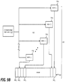
- the storage request 465 may include an identifier of the StorBlock (Stor_ID) 500 that indicates where content is currently being written as shown in the first illustrative example 580 . It is contemplated that the number of SubStors requested may be included in the storage request 465 . Where cache management logic 450 is not writing to any particular StorBlock, the Stor_ID 510 may be set to a particular value (e.g., NULL, zero, etc.) as shown in the second illustrative example 585 . Although not shown, it is contemplated that a number of SubStors may be static (e.g. one SubStor per storage request) or may be dynamic. In a dynamic configuration, the number of SubStors requested may be set as a default to “1”, but with visibility of the flow associated with the packet under analysis, it is contemplated that it may be desirable to request allocation of multiple SubStors.
- Stor_ID StorBlock
- the number of SubStors requested may be included in the storage request
- the store service logic 430 receives the storage request 465 and determines whether the requested storage area can be provided in the same StorBlock currently being used by the cache management logic 450 . If so, the store service logic 430 provides, in a response 520 , a logical identifier of the allocated SubStor (hereinafter “logical SubStor_ID” 530 ) and optionally the logical Stor_ID 540 to the cache management logic 450 .
- logical SubStor_ID a logical identifier of the allocated SubStor
- the store service logic 430 provides a Stor_ID 550 and a Substor_ID 560 for a new StorBlock to the cache management logic 450 as shown in the third illustrative example 590 .
- a storage logic may be maintained over a file system.
- the StorBlocks are directories and the StorBlock header is a file identified by Stor_ID 550 .
- the SubStors identified by corresponding SubStor_IDs 560 form sub-directories and the SubStor header and SubStor contents are files within the respective sub-directories.
- the cache management logic 450 is responsible for analyzing incoming packets to determine whether a packet include duplicated data, namely data already detected in its analysis of a prior packet, and whether the duplicated data would be stored in the same StorBlock. If so, the deduplication logic 455 may be activated to generate a suitable deduplication reference. The cache management logic 450 further manages the allocation of information associated with the analyzed packets into the SubStors.
- the cache management logic 450 analyzes a chunk of data e.g., 16-512 bytes) within a packet under analysis (to determine whether the chunk of data includes duplicated data. Such analysis may include the hash logic 440 conducting one or more hash operations on the chunk of data to produce a content-based hash value. The chunk size is maintained, but the starting point for the chunk of data may be adjusted to increase or decrease the amount of deduplication operations conducted by the network sensor engine 300 1 .
- the cache management logic 450 compares the content-based hash value to a first level content analysis device, such as a type of pre-filter (e.g., bloom filter for example. If a match, the content-based hash value is compared to stored contents within the data (dedup) cache 480 . If a match is detected and the duplicated data is stored in the same StorBlock as the matched hash value, the cache management logic 450 activates the deduplication logic 455 to conduct a deduplication operation by writing a deduplication reference in the header of the packet under analysis and removing such data from the stored packet content.
- a type of pre-filter e.g., bloom filter for example
- the cache management logic 450 does not activate the deduplication logic 455 to refrain for now from conducting a deduplication operation that data. Subsequent deduplication operations may later occur for duplicated content within the same StorBlock.
- Compression logic 460 handles compression of SubStor contents prior to being written to physical storage.
- the compression is performed after deduplication and may be conducted on the body of the packet under analysis and perhaps a portion or the entire header of the packet. It is contemplated that the size of the SubStors can be manipulated to adjust for gains in storage after compression is conducted. Of course, when the packets are retrieved, the SubStor needs to be decompressed before extracting the content of the packet data.
- FIG. 4B Another illustrative embodiment is illustrated in FIG. 4B , in which the packet processing engine 410 is represented as software that is stored within persistent storage 495 and executed by one or more hardware processors. It is further noted that the storage logic 470 may be implemented as a software driver that controls storage within persistent storage 495 .
- each StorBlock (e.g., StorBlock 110 1 ) includes a header 600 and a body 620 .
- the body 620 includes one or more SubStors 120 1 - 120 N , where each of these SubStor 120 i (1 ⁇ i ⁇ N) includes a header 630 and a body 660 , as shown.
- the body 660 of each SubStor 120 i includes one or more packets 150 1 - 150 P , which further includes a packet header 670 and a packet body 690 , as described below.
- the header 600 of StorBlock 110 1 includes timestamp information 605 and a Logical-to-Physical SubStor_ID mapping 610 and a Physical SubStor_ID-to-StorBlock_Offset mapping 615 .
- the mappings 610 and 615 provide information to identify SubStors 120 1 - 120 N within a particular StorBlock 110 1 and their placement within the StorBlock 110 1 . It is contemplated that, in one embodiment, the mappings 610 and 615 may be one unified table while may be multiple tables in another embodiment.
- the timestamp information 605 includes a first (start) timestamp 607 that identifies a time (e.g., date and time with any granularity including down to milliseconds) when a first SubStor 120 1 of the StorBlock 110 1 is allocated to the redundancy elimination logic 435 by the store service logic 430 .
- the timestamp information 605 includes a second (end) timestamp 609 that identifies the time at which the last SubStor 120 N of the StorBlock 110 1 is allocated.
- the timestamp information 605 allows for queries to the network sensor device 300 1 for packet data within a particular period of time.
- the Logical-to-Physical SubStor_ID mapping 610 includes a plurality of entries 611 , where each entry includes a unique logical SubStor_ID (e.g., local SubStor_ID 612 ) along with a corresponding physical SubStor_ID (e.g., physical SubStor_ID 613 ).
- a unique logical SubStor_ID e.g., local SubStor_ID 612
- a corresponding physical SubStor_ID e.g., physical SubStor_ID 613
- the storage service logic 430 is responsible for allocating the SubStors 120 1 - 120 N in response to storage requests by the redundancy elimination logic 435 , upon allocation of a SubStor (e.g., SubStor 120 1 ), the storage service logic 430 also assigns the logical SubStor_ID 612 to that allocated SubStor (e.g., SubStor 120 1 ). Hence, the logical SubStor_ID 612 is stored in the Logical-to-Physical SubStor_ID mapping 610 to identify SubStor 120 1 .
- SubStor 120 1 having SubStor_ID 612 reaches the prescribed capacity threshold, information (e.g., body 660 and/or header 630 ) within the SubStor 120 1 is compressed and the compressed SubStor 120 1 is returned to store service logic 430 , the store service logic 430 assigns the physical SubStor_ID 613 to SubStor 120 1 .
- the physical SubStor_ID 613 is a value that represents placement within the StorBlock 110 1 .
- SubStors 120 1 - 120 N may be allocated in one order, but written to physical storage in a different order, the Logical-to-Physical SubStor_ID mapping 610 maintains such ordering.
- the Physical SubStor_ID-to-StorBlock_Offset mapping 615 maintains correspondence between the physical SubStor_IDs and their offsets within the StorBlock. More specifically, while each Physical SubStor_ID identifies the order that the SubStor is written to the physical storage, the offset identifies the location where the particular SubStor is located within its StorBlock (e.g., memory address offset from the starting address of the StorBlock, sector/block offset from the starting sector/block of the StorBlock, etc.).
- the header 630 of SubStor 120 i includes the logical SubStor_ID 635 , timestamp information 640 , a Packet_ID-to-Offset mapping 645 , a Packet Linked List information 650 and compression dictionary references 655 .
- the SubStor header 630 includes information that identifies (i) the particular SubStor (e.g., SubStor 120 i ); (ii) information from which packets are maintained by SubStor 120 i ; and (iii) information associated with the compression conducted on at least the body 660 of SubStor 120 i .
- the timestamp information 640 includes a first (start) timestamp 642 that identifies a time when the cache management logic 450 stores a first packet 150 1 within SubStor 120 i and a second (end) timestamp 644 that identifies a time when a last packet 150 P is stored within SubStor 120 i
- the timestamp information 640 provides greater granularity for network sensor device 200 1 in searches for packet data within the particular period of time.
- the Packet_ID-to-Offset mapping 645 includes a plurality of entries 646 , where each entry includes a unique Packet_ID (e.g., Packet_ID 647 ) along with a corresponding offset 648 that identifies the location within the SubStor 120 i where the particular packet information is located (e.g., memory address offset from the starting address of the SubStor 120 i , sector/block offset from the starting sector/block of the SubStor 120 i , etc.)
- Packet_ID e.g., Packet_ID 647
- a corresponding offset 648 that identifies the location within the SubStor 120 i where the particular packet information is located (e.g., memory address offset from the starting address of the SubStor 120 i , sector/block offset from the starting sector/block of the SubStor 120 i , etc.)
- the Packet Linked List information 650 is responsible for maintaining information to identify which packets belong to a particular flow. More specifically, SubStor 120 i may store packets associated with a plurality of flows. The packets associated with each flow are linked together by the flow manager 320 and the packet link list information 650 identifies the particular packet(s) representing the start or end of one or more packet linked lists (e.g., head or tail of the packet linked list(s)). This enables identification as to which packets stored with the SubStor are associated with which flows.
- packet linked lists e.g., head or tail of the packet linked list(s)
- the compression dictionary references 655 include information associated with the compression used to compress the body 660 and/or portions of the header 630 .
- the compression dictionary references 655 may include a name and/or version of the compression algorithm, sizes used for the compression or the like. This allows different SubStors to utilize different compression types, notably where different SubStors are allocated to control storage of different types of data (e.g. encrypted, clear) and/or from different sources. For instance, encrypted data may require lossless compression due to the fact that it is unclear how the loss of particular storage element will affect the resultant data in the clear. Also, some enterprises may have certain high-priority endpoint devices (e.g., server with company's financials, etc.) which may inquire more complex compression algorithms to be used in efforts to further obfuscate the data.
- high-priority endpoint devices e.g., server with company's financials, etc.
- each packet 150 1 - 150 P stored within the SubStor 120 i includes the packet header 670 and packet body 690 .
- the packet header 670 includes timestamp information 675 and deduplication references 680 while the packet body 690 includes the contents of the packet without the duplicative data as identified by the deduplication references 680 .
- the timestamp information 675 includes a first (start) timestamp that identifies a time when the cache management logic 450 assigns the packet 150 2 to the SubStor 120 i .
- the deduplicative references 680 identify the locations within the StorBlock 110 1 where duplicated data within a previously analyzed packet is stored. As a result, this duplicated data may be removed from the packet 150 2 and is not stored in packet body 690 .
- FIG. 7 an exemplary embodiment of a flowchart directed to redundancy elimination operations conducted by the hash logic 440 , cache management logic 450 and deduplication logic 455 of the redundancy elimination logic 435 of FIG. 4A is shown.
- one or more packets are received by the redundancy elimination logic 435 for analysis (item 700 ).
- a content-based hash value is generated for a first portion of the packet data (item 705 ).
- the content-based hash value may include a rolling hash value that is generated by conducting a one-way hash operation on the first portion of the packet data within a prescribed window and modifying a position of the window as it moves through the packet data.
- a rolling hash value that is generated by conducting a one-way hash operation on the first portion of the packet data within a prescribed window and modifying a position of the window as it moves through the packet data.
- other techniques may be used to produce the content-based hash value.
- the cache management logic determines whether the content-based hash value is contained in the bloom filter (item 710 ). If not, a bit array representation of the hash value is stored (item 715 ). However, if a match is determined in the bloom filter, the cache management logic determines whether the hash value is currently stored within the data (dedup) cache that represents packet data already stored within the same StorBlock (item 720 ). If so, the analyzed portion of the packet data is considered to be duplicative of packet data already stored within the same StorBlock and offsets are set (items 725 and 730 ).
- the offsets identify a starting point (e.g., byte location within the packets) for the analyzed packet data (sometimes referred to herein as “DEST_Offset”) and the previously stored packet data (sometimes referred to herein as “SRC_Offset”).
- further analysis of the packet data may be conducted to determine if any additional data, immediately prior to and/or after the first portion of the packet data, has already been stored within the same StorBlock until no match is detected (items 735 and 740 ).
- the offset associated with the additional data in the analyzed packet data (DEST_Offset) and the offset associated with the previously stored packet data (SRC_Offset) are adjusted and maintained to be written as part of the deduplication reference (item 745 ).
- This iterative process may be conducted to generate content-based hash values that are directed to the total duplicative data being discovered.
- the deduplication reference includes the logical SubStor_ID; Packet_ID; length (in a selected measuring unit such as bytes) of the duplicated content; SRC_Offset (in the selected measuring unit); and/or DEST_Offset (in the selected measuring unit).
- the content-based hash value may be stored within the data cache or representative data associated with the content-based hash value is stored within the bloom filter as described below in FIGS. 9-10 (item 755 ).
- the content-based hash value 820 is compared to stored content-based hash values 830 within data cache 480 to determine if the network sensor engine has previously stored the duplicated content associated with another packet within the first StorBlock 110 1 .
- the deduplication logic 455 of the redundancy elimination logic 435 to expand the packet data under analysis, in accordance with a measuring unit of a selected granularity (e.g., bit, nibble, byte, word, Dword, etc.), until it is determination is made that that the 32-byte chunk 810 along with a predetermined number of memory elements (e.g., a predetermined number of bytes such as 50 bytes for example) match bytes 1250 to 1331 of the second packet 150 2 .
- a predetermined number of memory elements e.g., a predetermined number of bytes such as 50 bytes for example
- the content-based hash value may be directed to a smaller section of the packet data than the actual duplicated data.
- the cache management logic 450 within the packet processing engine 410 is responsible for prioritizing and controlling storage of content-based hash values associated with duplicated data in order to ensure retention of information that may be useful in subsequent malware analysis.
- the cache management logic 450 utilizes a first level content analysis device 900 to regulate the size of the data (dedup) cache 910 in order to reduce the amount of memory required to maintain millions and perhaps billions of different content-based hash values representative of different types of packet data.
- the first level content analysis device 900 and the data (dedup) cache 480 operate in concert, where the first level content analysis device 900 is adapted to store a first predetermined number of content-based hash values using a lesser amount of memory resources than the data cache corresponding in size.
- a bloom filter may be deployed as the first level content analysis device 900 that is responsible for uploading active content-based hash values to the data (dedup) cache 480 .
- the first level content analysis device 900 When deployed as a bloom filter, the first level content analysis device 900 is not adapted to store content-based hash values per se. Rather, the first level content analysis device 900 is configured to identify whether input data 910 has not been analyzed previously, and similarly, may identify whether the input data 910 has possibly been analyzed previously, where false positives may occur depending on the array size of the first level content analysis device.
- the first level content analysis device 900 stores values derived from the content-based hash values (input data 910 ) as part of analyzed “set”, but such storage requires less memory.
- the content-based hash value 910 may undergo multiple (“j”, 1 ⁇ j ⁇ k) different hash operations 930 that generate hash results 935 , each of which maps to a position 940 1 - 940 j with uniform random distribution on the bit array 920 so as to collectively map to j bits on the bit array 920 .
- the content-based hash value 910 is input into each of j hash functions to get j array positions 940 1 - 940 j . If any of the bits at these positions are “0”, the content-based hash value has not been previously detected by the bloom filter 900 . Where the content-based hash value may have already been previously detected by the bloom filter 900 , all the j bits would be set to “1” to denote a successful match.
- the content-based hash value 910 is added to the data cache 480 if it has not been previously added.
- the bloom filter 900 identifies that the content-based hash value 910 may have been previously analyzed but is not already stored in the data cache 480
- the content-based hash value is added to the data cache 480 .
- active content-based hash values are stored within the data cache 480 for prolonged retention in contrast to inactive content-based hash values.
- the first level content analysis device 900 is deployed as a bloom filter, continuous addition and deletion of inactive content-based hash values within the data cache 480 may be mitigated.
- the cache management logic 450 may utilize an “aged” bloom filter. More specifically, according to a first embodiment, at least two copies 1000 and 1010 forming the bloom filter 900 may be maintained, where a first bloom filter 1000 initially serves as an active filter and a second bloom filter 1010 initially serves as a “shadow” filter.
- New content-based hash values 1020 are provided to and processed only by the active bloom filter 1000 , but a lookup conducted by the cache management logic 450 accesses both the active and shadow bloom filters 1000 and 1010 .
- a prescribed threshold e.g., storage capacity of the active bloom filter exceeds a prescribed threshold, which may be decided either by number of bytes used, time, or, total number of content-based hash values added
- the active bloom filter 1000 becomes the new shadow bloom filter 1030 and the shadow bloom filter 1010 is erased and now becomes the new active bloom filter 1040 .
- active content-based hash values are retained as part of the collective bloom filter 900 , while lesser occurrences of the content-based hash values disappear in this rotation.
- the first level cache can use a third bloom filter, which represents all entries of the second level (dedup) cache that could be evicted from the first level cache during the aging process using the pair of bloom filters as described above. More specifically, according to this embodiment, at least three copies 1100 , 1110 and 1120 forming the bloom filter 900 may be maintained, where a first bloom filter 1100 initially serves as an active filter, a second bloom filter 1110 initially serves as a shadow filter and a third bloom filter 1120 initially serves as a redundant filter that includes representative data of content-based hash values currently contained within the data cache 480 .
- new content-based hash values 1130 are provided to and processed only by the active bloom filter 1100 , but a lookup conducted by the cache management logic 450 accesses all bloom filters 1100 , 1110 and 1120 .
- a prescribed threshold e.g., storage capacity of the active bloom filter exceeds a prescribed threshold, which may be decided either by number of bytes used, time, or, total number of content-based hash values added
- the active bloom filter 1100 becomes the new redundant bloom filter 1140 and representative data of content-based hash values that are present in the data (dedup) cache without representative data currently stored within the new redundant bloom filter 1140 are added thereto.
- the redundant bloom filter 1110 becomes the new shadow filter 1150 and the shadow bloom filter 1110 is erased and now becomes the new active bloom filter 1160 .
- information associated with active content-based hash values is retained as part of the collective bloom filter 900 for a period of time beyond the aging of hash values from the data (dedup) cache 480 of FIG. 4A .
- Lesser occurrences of the content-based hash values effectively disappear in this rotation but are retained in accordance with aging policies for the data (dedup) cache.
- every flow exports a record for each Substor that includes at least one packet, where the record (referred to as a “dedup record”) includes the SubStor_ID, a Stor_Id for that SubStor, and a Packet_ID.
- the Packet_ID is a first or last packet associated with a packet linked list. Depending on its direction that is determined based on implementation performance and/or optimizations, the packet linked list allows for (i) access of a first packet identifier (Packet_ID) and progressing through the rest of the packet linked list or (ii) access of a last Packet_ID and progressing in reverse through the rest of the packet linked list until accessing the first Packet_ID.
- These dedup records are stored within the data analysis engine 320 and/or network sensor engine 300 of FIG. 3 .
- a query is provided to a list of flows for which we need packets. For each of the flows, we extract their respective dedup records.
- the dedup records provide information including the size (e.g., number of packets or other size parameter) of the generated packet capture (pcap) and collectively provide, for each flow direction, how many packets (or bytes) are in that flow, which is part of the network sensor data exchanged between the network sensor engine and the data analysis engine. This information may be used interactively with a user interface (UI) to decide on a final presentation of the packet.
- UI user interface
- Examples of type of presentations may include (1) a few packets in a message; (2) a small pcap placed in storage within the sensor and the path provided to the data analysis engine or UI; (3) a list of pcaps that could be in overlapping time order for each of the SubStors; and/or (4) a merged pcap with all the packets in time order (or the merged pcap split into smaller pcaps with packets in time order).
- alternate retrieval models could include (a) Secure Copy (SCP) or File Transfer Protocol (FTP) a packet to a remote location, and/or (b) copying to an NFS or iSCSI mounted remote target.
- SCP Secure Copy
- FTP File Transfer Protocol
- the records are then sorted based on Stor_ID, SubStor_ID with a list of first/last Packet_IDs associated with packet linked lists. This ensures that each SubStor is decompressed (optionally decrypted prior to that) and undergoes a single fetch of the SubStor for all of the flows that has packets in that SubStor.
- the resultant packets should be in time order as the packet_IDs are written on a first-come basis.
- the packets need to be un-deduped by resolving the references in these packets. Hence, only references in the required packets need to be resolved.
- Undeduping only the packets that has reference need to be reconstructed. This may result in further Substor fetches, but due to our scheme of referring to one single packet for specific reference this chain is greatly reduced. Also, as further optimization, only the regions in the packet that are referenced needs to be undeduped at this time.
- Extraction may be further sped up by performing multiple processes for each Substor, where StorBlock-based retrieval may optimize disk fetches.
- StorBlock-based retrieval may optimize disk fetches.
- serial processing per StorBlock may provide more efficient resolution of dedup references.
- sensor CPU utilization could be used to decide how many parallel retrievals can be launched.
Landscapes
- Engineering & Computer Science (AREA)
- Computer Networks & Wireless Communication (AREA)
- Signal Processing (AREA)
- Information Retrieval, Db Structures And Fs Structures Therefor (AREA)
Abstract
Description
Claims (20)
Priority Applications (2)
| Application Number | Priority Date | Filing Date | Title |
|---|---|---|---|
| US14/743,902 US10645002B2 (en) | 2014-06-20 | 2015-06-18 | System, apparatus and method for managing redundancy elimination in packet storage during observation of data movement |
| PCT/US2015/036976 WO2015196196A1 (en) | 2014-06-20 | 2015-06-22 | System, apparatus and method for managing redundancy elimination in packet storage during observation of data movement |
Applications Claiming Priority (2)
| Application Number | Priority Date | Filing Date | Title |
|---|---|---|---|
| US201462015351P | 2014-06-20 | 2014-06-20 | |
| US14/743,902 US10645002B2 (en) | 2014-06-20 | 2015-06-18 | System, apparatus and method for managing redundancy elimination in packet storage during observation of data movement |
Publications (2)
| Publication Number | Publication Date |
|---|---|
| US20150372910A1 US20150372910A1 (en) | 2015-12-24 |
| US10645002B2 true US10645002B2 (en) | 2020-05-05 |
Family
ID=54870676
Family Applications (1)
| Application Number | Title | Priority Date | Filing Date |
|---|---|---|---|
| US14/743,902 Active US10645002B2 (en) | 2014-06-20 | 2015-06-18 | System, apparatus and method for managing redundancy elimination in packet storage during observation of data movement |
Country Status (2)
| Country | Link |
|---|---|
| US (1) | US10645002B2 (en) |
| WO (1) | WO2015196196A1 (en) |
Cited By (2)
| Publication number | Priority date | Publication date | Assignee | Title |
|---|---|---|---|---|
| US11212219B1 (en) * | 2020-06-26 | 2021-12-28 | Lenovo Enterprise Solutions (Singapore) Pte. Ltd. | In-band telemetry packet size optimization |
| US11809378B2 (en) | 2021-10-15 | 2023-11-07 | Morgan Stanley Services Group Inc. | Network file deduplication using decaying bloom filters |
Families Citing this family (21)
| Publication number | Priority date | Publication date | Assignee | Title |
|---|---|---|---|---|
| US10275541B2 (en) | 2016-08-05 | 2019-04-30 | Micron Technology, Inc. | Proactive corrective actions in memory based on a probabilistic data structure |
| US10417133B2 (en) | 2017-01-26 | 2019-09-17 | International Business Machines Corporation | Reference cache maintenance optimizer |
| US12425357B2 (en) * | 2017-02-12 | 2025-09-23 | Mellanox Technologies Ltd. | Communication apparatus generating and eliminating redundant data packets |
| KR102157354B1 (en) * | 2017-11-20 | 2020-09-17 | 삼성전자 주식회사 | Systems and methods for efficient compresesed cache line storage and handling |
| US11165849B2 (en) * | 2018-07-31 | 2021-11-02 | Pixspan, Inc. | Accelerated cloud data transfers using optimized file handling and a choice of speeds across heterogeneous network paths |
| KR102025921B1 (en) * | 2018-08-09 | 2019-09-26 | 숭실대학교산학협력단 | Method of data caching in delay tolerant network based on information centric network, computer readable medium and device for performing the method |
| US11347808B1 (en) * | 2018-12-03 | 2022-05-31 | Amazon Technologies, Inc. | Dynamically-adaptive bloom-filter |
| US12204781B2 (en) * | 2019-05-10 | 2025-01-21 | Dell Products L.P. | System and method for performance based dynamic optimal block size data deduplication |
| US11563771B2 (en) * | 2019-11-25 | 2023-01-24 | Cisco Technology, Inc. | Network telemetry collection with packet metadata filtering |
| KR102894139B1 (en) * | 2019-12-20 | 2025-12-03 | 에스케이하이닉스 주식회사 | Data Storage Apparatus and Operation Method Thereof |
| US12603895B2 (en) | 2019-12-23 | 2026-04-14 | Cisco Technology, Inc. | Packet metadata capture in a software-defined network |
| US10860717B1 (en) | 2020-07-01 | 2020-12-08 | Morgan Stanley Services Group Inc. | Distributed system for file analysis and malware detection |
| US11061879B1 (en) | 2020-07-01 | 2021-07-13 | Morgan Stanley Services Group Inc. | File indexing and retrospective malware detection system |
| US10990676B1 (en) | 2020-07-01 | 2021-04-27 | Morgan Stanley Services Group Inc. | File collection method for subsequent malware detection |
| US11366764B2 (en) * | 2020-09-29 | 2022-06-21 | International Business Machines Corporation | Managing a least-recently-used data cache with a persistent body |
| US12174806B2 (en) * | 2021-02-02 | 2024-12-24 | Maxlinear, Inc. | Hashing for deduplication through skipping selected data |
| CN115562562A (en) * | 2021-07-01 | 2023-01-03 | 伊姆西Ip控股有限责任公司 | Method, device and program product for managing computing system based on client/server architecture |
| US20240348768A1 (en) * | 2021-08-31 | 2024-10-17 | Siemens Industry Software Inc. | Hardware-based sensor analysis |
| US20230221864A1 (en) * | 2022-01-10 | 2023-07-13 | Vmware, Inc. | Efficient inline block-level deduplication using a bloom filter and a small in-memory deduplication hash table |
| US12494998B2 (en) | 2022-06-06 | 2025-12-09 | Cisco Technology, Inc. | Network metadata reporting |
| US12210453B2 (en) * | 2023-06-30 | 2025-01-28 | Genesys Cloud Services, Inc. | Technologies for configurable caching, deduplication, and rate limit handling |
Citations (20)
| Publication number | Priority date | Publication date | Assignee | Title |
|---|---|---|---|---|
| US5331646A (en) * | 1992-05-08 | 1994-07-19 | Compaq Computer Corporation | Error correcting code technique for improving reliablility of a disk array |
| US5813009A (en) | 1995-07-28 | 1998-09-22 | Univirtual Corp. | Computer based records management system method |
| US20060095695A1 (en) | 2004-11-02 | 2006-05-04 | Rodger Daniels | Copy operations in storage networks |
| US20070150691A1 (en) | 2005-12-27 | 2007-06-28 | Illendula Ajith K | Methods and apparatus to share a thread to reclaim memory space in a non-volatile memory file system |
| US20080294696A1 (en) * | 2007-05-22 | 2008-11-27 | Yuval Frandzel | System and method for on-the-fly elimination of redundant data |
| US20090106843A1 (en) | 2007-10-18 | 2009-04-23 | Pil-Yong Kang | Security risk evaluation method for effective threat management |
| US20090234870A1 (en) * | 2008-03-14 | 2009-09-17 | International Business Machines Corporation | Ordering compression and deduplication of data |
| US20100098318A1 (en) * | 2008-10-20 | 2010-04-22 | Jpmorgan Chase Bank, N.A. | Method and System for Duplicate Check Detection |
| US20110016091A1 (en) * | 2008-06-24 | 2011-01-20 | Commvault Systems, Inc. | De-duplication systems and methods for application-specific data |
| US20110035802A1 (en) | 2009-08-07 | 2011-02-10 | Microsoft Corporation | Representing virtual object priority based on relationships |
| US7913303B1 (en) | 2003-01-21 | 2011-03-22 | International Business Machines Corporation | Method and system for dynamically protecting a computer system from attack |
| US20120102136A1 (en) | 2010-10-21 | 2012-04-26 | Lancaster University | Data caching system |
| US20120102003A1 (en) * | 2010-10-20 | 2012-04-26 | International Business Machines Corporation | Parallel data redundancy removal |
| US20130018852A1 (en) | 2011-07-15 | 2013-01-17 | International Business Machines Corporation | Deleted data recovery in data storage systems |
| US20130132653A1 (en) | 2010-02-26 | 2013-05-23 | Apple Inc. | Data partitioning scheme for non-volatile memories |
| US8495747B1 (en) | 2010-03-31 | 2013-07-23 | Mcafee, Inc. | Prioritizing asset remediations |
| US20140181432A1 (en) | 2012-12-26 | 2014-06-26 | Western Digital Technologies, Inc. | Priority-based garbage collection for data storage systems |
| US20140237545A1 (en) | 2013-02-19 | 2014-08-21 | Marble Security | Hierarchical risk assessment and remediation of threats in mobile networking environment |
| US20150281260A1 (en) | 2013-03-07 | 2015-10-01 | Inquest | Integrated network threat analysis |
| US20150370723A1 (en) | 2014-06-20 | 2015-12-24 | Niara, Inc. | System, Apparatus and Method for Prioritizing the Storage of Content Based on a Threat Index |
Family Cites Families (1)
| Publication number | Priority date | Publication date | Assignee | Title |
|---|---|---|---|---|
| JP2899374B2 (en) * | 1990-07-16 | 1999-06-02 | 沖電気工業株式会社 | Decoder check circuit for semiconductor memory |
-
2015
- 2015-06-18 US US14/743,902 patent/US10645002B2/en active Active
- 2015-06-22 WO PCT/US2015/036976 patent/WO2015196196A1/en not_active Ceased
Patent Citations (20)
| Publication number | Priority date | Publication date | Assignee | Title |
|---|---|---|---|---|
| US5331646A (en) * | 1992-05-08 | 1994-07-19 | Compaq Computer Corporation | Error correcting code technique for improving reliablility of a disk array |
| US5813009A (en) | 1995-07-28 | 1998-09-22 | Univirtual Corp. | Computer based records management system method |
| US7913303B1 (en) | 2003-01-21 | 2011-03-22 | International Business Machines Corporation | Method and system for dynamically protecting a computer system from attack |
| US20060095695A1 (en) | 2004-11-02 | 2006-05-04 | Rodger Daniels | Copy operations in storage networks |
| US20070150691A1 (en) | 2005-12-27 | 2007-06-28 | Illendula Ajith K | Methods and apparatus to share a thread to reclaim memory space in a non-volatile memory file system |
| US20080294696A1 (en) * | 2007-05-22 | 2008-11-27 | Yuval Frandzel | System and method for on-the-fly elimination of redundant data |
| US20090106843A1 (en) | 2007-10-18 | 2009-04-23 | Pil-Yong Kang | Security risk evaluation method for effective threat management |
| US20090234870A1 (en) * | 2008-03-14 | 2009-09-17 | International Business Machines Corporation | Ordering compression and deduplication of data |
| US20110016091A1 (en) * | 2008-06-24 | 2011-01-20 | Commvault Systems, Inc. | De-duplication systems and methods for application-specific data |
| US20100098318A1 (en) * | 2008-10-20 | 2010-04-22 | Jpmorgan Chase Bank, N.A. | Method and System for Duplicate Check Detection |
| US20110035802A1 (en) | 2009-08-07 | 2011-02-10 | Microsoft Corporation | Representing virtual object priority based on relationships |
| US20130132653A1 (en) | 2010-02-26 | 2013-05-23 | Apple Inc. | Data partitioning scheme for non-volatile memories |
| US8495747B1 (en) | 2010-03-31 | 2013-07-23 | Mcafee, Inc. | Prioritizing asset remediations |
| US20120102003A1 (en) * | 2010-10-20 | 2012-04-26 | International Business Machines Corporation | Parallel data redundancy removal |
| US20120102136A1 (en) | 2010-10-21 | 2012-04-26 | Lancaster University | Data caching system |
| US20130018852A1 (en) | 2011-07-15 | 2013-01-17 | International Business Machines Corporation | Deleted data recovery in data storage systems |
| US20140181432A1 (en) | 2012-12-26 | 2014-06-26 | Western Digital Technologies, Inc. | Priority-based garbage collection for data storage systems |
| US20140237545A1 (en) | 2013-02-19 | 2014-08-21 | Marble Security | Hierarchical risk assessment and remediation of threats in mobile networking environment |
| US20150281260A1 (en) | 2013-03-07 | 2015-10-01 | Inquest | Integrated network threat analysis |
| US20150370723A1 (en) | 2014-06-20 | 2015-12-24 | Niara, Inc. | System, Apparatus and Method for Prioritizing the Storage of Content Based on a Threat Index |
Non-Patent Citations (6)
| Title |
|---|
| PCT/US2015/036976 filed Jun. 22, 2015 International Search Report and Written Opinion dated Sep. 14, 2015. |
| PCT/US2015/036987 filed Jun. 22, 2015 International Search Report and Written Opinion dated Sep. 21, 2015. |
| U.S. Appl. No. 14/743,892 filed Jun. 18, 2015 Advisory Action dated Sep. 19, 2017. |
| U.S. Appl. No. 14/743,892 filed Jun. 18, 2015 Final Office Action dated Jun. 30, 2017. |
| U.S. Appl. No. 14/743,892 filed Jun. 18, 2015 Non-Final Office Action dated Dec. 1, 2017. |
| U.S. Appl. No. 14/743,892 filed Jun. 18, 2015 Non-Final Office Action dated Dec. 19, 2016. |
Cited By (2)
| Publication number | Priority date | Publication date | Assignee | Title |
|---|---|---|---|---|
| US11212219B1 (en) * | 2020-06-26 | 2021-12-28 | Lenovo Enterprise Solutions (Singapore) Pte. Ltd. | In-band telemetry packet size optimization |
| US11809378B2 (en) | 2021-10-15 | 2023-11-07 | Morgan Stanley Services Group Inc. | Network file deduplication using decaying bloom filters |
Also Published As
| Publication number | Publication date |
|---|---|
| US20150372910A1 (en) | 2015-12-24 |
| WO2015196196A1 (en) | 2015-12-23 |
Similar Documents
| Publication | Publication Date | Title |
|---|---|---|
| US10645002B2 (en) | System, apparatus and method for managing redundancy elimination in packet storage during observation of data movement | |
| US10521358B2 (en) | System, apparatus and method for prioritizing the storage of content based on a threat index | |
| US11048822B2 (en) | System, apparatus and method for anonymizing data prior to threat detection analysis | |
| US11627148B2 (en) | Advanced threat detection through historical log analysis | |
| US8112477B2 (en) | Content identification for peer-to-peer content retrieval | |
| US10904274B2 (en) | Signature pattern matching testing framework | |
| US9871816B2 (en) | Systems and methods for security management of multi-client based distributed storage | |
| US9092146B2 (en) | Dynamically varying transfer size in a storage device for improved performance | |
| KR101312125B1 (en) | Contents filtering apparatus and method thereof | |
| US20210209179A1 (en) | System and methods for dynamic generation of object storage datasets from existing file datasets | |
| US9335945B2 (en) | Transfer size monitor, determination, and optimization engine for storage devices | |
| US12197578B1 (en) | Automated virtualized storage snapshotting responsive to ransomware detection | |
| US10521423B2 (en) | Apparatus and methods for scanning data in a cloud storage service | |
| US12086250B1 (en) | Detecting anomalous I/O patterns indicative of ransomware attacks | |
| CN115914369B (en) | Network target range log file acquisition proxy gateway, acquisition system and method | |
| US12058169B1 (en) | Automated ransomware recovery using log-structured storage | |
| EP4664332A1 (en) | Data processing method, processor, storage device, interface card, and storage medium | |
| US11762984B1 (en) | Inbound link handling | |
| US8694659B1 (en) | Systems and methods for enhancing domain-name-server responses | |
| US12554848B2 (en) | Rule generation using entropy profile for malware detection | |
| CN119011609A (en) | Cloud storage method, device, equipment and medium based on intelligent allocation of network equipment | |
| US20230259617A1 (en) | Topology-based event suppression | |
| US20080162815A1 (en) | Method and system to preview new cacheable content | |
| WO2026025112A1 (en) | Systems, methods, and media for virtual disk devices | |
| CN116800777A (en) | Message processing method, device, electronic equipment and storage medium |
Legal Events
| Date | Code | Title | Description |
|---|---|---|---|
| AS | Assignment |
Owner name: NIARA, INC., CALIFORNIA Free format text: ASSIGNMENT OF ASSIGNORS INTEREST;ASSIGNORS:JANAKIRAMAN, RAMSUNDAR;PALKAR, PRASAD;PARTHASARATHY, MOHAN;AND OTHERS;REEL/FRAME:037960/0171 Effective date: 20150605 |
|
| AS | Assignment |
Owner name: HEWLETT PACKARD ENTERPRISE DEVELOPMENT LP, TEXAS Free format text: ASSIGNMENT OF ASSIGNORS INTEREST;ASSIGNOR:ARUBA NETWORKS, INC.;REEL/FRAME:045921/0055 Effective date: 20171115 |
|
| STPP | Information on status: patent application and granting procedure in general |
Free format text: DOCKETED NEW CASE - READY FOR EXAMINATION |
|
| STPP | Information on status: patent application and granting procedure in general |
Free format text: NON FINAL ACTION MAILED |
|
| STPP | Information on status: patent application and granting procedure in general |
Free format text: RESPONSE TO NON-FINAL OFFICE ACTION ENTERED AND FORWARDED TO EXAMINER |
|
| STPP | Information on status: patent application and granting procedure in general |
Free format text: NOTICE OF ALLOWANCE MAILED -- APPLICATION RECEIVED IN OFFICE OF PUBLICATIONS |
|
| AS | Assignment |
Owner name: ARUBA NETWORKS, INC., CALIFORNIA Free format text: ASSIGNMENT OF ASSIGNORS INTEREST;ASSIGNOR:NIARA, INC.;REEL/FRAME:051644/0671 Effective date: 20170807 |
|
| STCF | Information on status: patent grant |
Free format text: PATENTED CASE |
|
| FEPP | Fee payment procedure |
Free format text: ENTITY STATUS SET TO UNDISCOUNTED (ORIGINAL EVENT CODE: BIG.); ENTITY STATUS OF PATENT OWNER: LARGE ENTITY |
|
| MAFP | Maintenance fee payment |
Free format text: PAYMENT OF MAINTENANCE FEE, 4TH YEAR, LARGE ENTITY (ORIGINAL EVENT CODE: M1551); ENTITY STATUS OF PATENT OWNER: LARGE ENTITY Year of fee payment: 4 |