US1064355A - Rail-joint. - Google Patents
Rail-joint. Download PDFInfo
- Publication number
- US1064355A US1064355A US65646211A US1911656462A US1064355A US 1064355 A US1064355 A US 1064355A US 65646211 A US65646211 A US 65646211A US 1911656462 A US1911656462 A US 1911656462A US 1064355 A US1064355 A US 1064355A
- Authority
- US
- United States
- Prior art keywords
- joint
- rails
- rail
- pins
- thought
- Prior art date
- Legal status (The legal status is an assumption and is not a legal conclusion. Google has not performed a legal analysis and makes no representation as to the accuracy of the status listed.)
- Expired - Lifetime
Links
- 238000010276 construction Methods 0.000 description 3
- 241000251468 Actinopterygii Species 0.000 description 1
- 230000002950 deficient Effects 0.000 description 1
- 238000004519 manufacturing process Methods 0.000 description 1
Images
Classifications
-
- E—FIXED CONSTRUCTIONS
- E01—CONSTRUCTION OF ROADS, RAILWAYS, OR BRIDGES
- E01B—PERMANENT WAY; PERMANENT-WAY TOOLS; MACHINES FOR MAKING RAILWAYS OF ALL KINDS
- E01B11/00—Rail joints
- E01B11/56—Special arrangements for supporting rail ends
- E01B11/62—Bridge chairs
Definitions
- An object of my invention is to provide a rail joint which is simple and one which is thought to obviate the necessity of manufacturing a number of parts to construct the same and thereby raising the cost.
- Another object of my invention is to provide a rail joint which is simple in construction and one which can be easily attached to'or removed from the rail which is now in use, and is also thought to positively prevent the spreading of the rails.
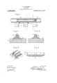
- FIG. 2 is a cross sectional view of my joint taken on line Y Y otFig. 1.
- Fig. 3 is a ctbss sectional view taken on line X X of Fig. 1.
- Fig. 4 is a sideele-vation of my joint.
- Fig. 5 is a fragmentary detailed view of a section of my joint.
Landscapes
- Engineering & Computer Science (AREA)
- Mechanical Engineering (AREA)
- Architecture (AREA)
- Civil Engineering (AREA)
- Structural Engineering (AREA)
- Brushes (AREA)
Description
A. L. MAUBERT. RAIL JOINT.
APPLICATION FILED 001224, 1911.
Patented June 10, 1913.
WITNESSES 31%; wait .[NVENTOR unrr stares raft:
ARTHUR L. MAUBE RT, QF GRETNA, LOUISIANA.
Rain-Joins.
Specification of Letters gatent. I Patented June 10, 191 3.,
t a Application fiIed October 24, 1911, "tsrial No. 656,462.
.10 d An object of my invention is to provide a rail joint which is simple and one which is thought to obviate the necessity of manufacturing a number of parts to construct the same and thereby raising the cost.
Another object of my invention is to provide a rail joint which is simple in construction and one which can be easily attached to'or removed from the rail which is now in use, and is also thought to positively prevent the spreading of the rails.
With the foregoing and other objects in view, my invention relates to such details of construction and in the arrangement and combination of parts as will be hereinafter fully described and specifically pointed out in the appended claims.
In describing my invention in detail reference will be had to the accompanying drawings wherein like characters denote like or corresponding parts throughout the several views, and in which Figure l is a side elevation of my improved rail joint the same being shown in place. Fig. 2 is a cross sectional view of my joint taken on line Y Y otFig. 1. Fig. 3 is a ctbss sectional view taken on line X X of Fig. 1. Fig. 4 is a sideele-vation of my joint. Fig. 5 is a fragmentary detailed view of a section of my joint.
In the drawings I have shown'the rails 1 and 2 supported by the ties It is well known in the art that heretofore fish plates have been ordinarily used. These not only proved deficient as connecting means, but also are provided with no means for preventing the spreading of the rail. The herein disclosed device is thought to securely join the rails together in sucha manner as to hold them securely upon the ties and it is thought the spreading of the same will also be obviated My improved j ointor connecting means is shown at 4 it having the bottom portion 5 and the side portions 5. The bottom portion-5"is adapted to he seat-ed in the ties 3 below the surfaceXthereof and the side portions 5 are adapted to be flush with the top of said ties. The ends of the rails l and 2 are inserted into said joint and a pin is inserted through the side portions 5 and throught-he ends of the rails whereby they are held securely thereto. I also find it advantageous to. provide a second securing means as is clearly shown in Figs. .Zand' 3. This meansis inserted through one side of 'my joint, througlrthe end of the rail and extends upwardly in the second side, there by engaging a notch 11 which is formed in the first named pin. The first pin I have shown at 6 and the second I have shown at :7. The slots which they enter I have shown in Fig. 5 and they are designated by the numorals 8 and 9. It is thought that aft the spikes 10 have been securely driven into the tie that my improved joint will be held securely thereon.
I desire it to be understood that I may make slight changes in the construction without departing from the spirit of my invention provided such changes fall .within the scope of the subjoined claims. It is also thoughtthat the advantages and novel features of my improved device will be appreciated.
Having thus fully described my invention what I claim as new and Letters Patent is 1. In a device of the character described,
the combination with a pair of rails, of side pieces in engagement with the adjacent ends. thereof, pins extending through said side pieces'and said rails, said pins being disposed near the upper edge of said side pieces, other pins disposed through said side pieces and said rails, one end of said last mentioned pins engaging the corresponding end of the other of said pins within one of said side members, as and torthe purpose forth and described.
2. In a device of the character described. the combination with a pair ofrails. of side members disposed in engagement with th adjacent ends thereof. pins connecting said side pieces and extending through said rails, other pins connecting said side pieces and extending through said rails, the dude of said first and second mentioned. pins be spaced apart on one side of the rails. other ends of said second mentioned j engaging the corresponding ends of a desire to secure by one of said side members, other pins connecting said side members and Extending through said raiis, the heads of said members being spaced apart, the other ends of said second mentioned pins engaging said notches in said first mentioned pins, as and for the purpose set forth and described.
ARTHUR L. MAUBERT.
' Witnesses ISAAC CAMBRE, DARCISE CAMBRE.
Copies of this patent may be obtained for five cents each, byaddressing the Commissioner of Patents. Washington, I). C.
Priority Applications (1)
| Application Number | Priority Date | Filing Date | Title |
|---|---|---|---|
| US65646211A US1064355A (en) | 1911-10-24 | 1911-10-24 | Rail-joint. |
Applications Claiming Priority (1)
| Application Number | Priority Date | Filing Date | Title |
|---|---|---|---|
| US65646211A US1064355A (en) | 1911-10-24 | 1911-10-24 | Rail-joint. |
Publications (1)
| Publication Number | Publication Date |
|---|---|
| US1064355A true US1064355A (en) | 1913-06-10 |
Family
ID=3132599
Family Applications (1)
| Application Number | Title | Priority Date | Filing Date |
|---|---|---|---|
| US65646211A Expired - Lifetime US1064355A (en) | 1911-10-24 | 1911-10-24 | Rail-joint. |
Country Status (1)
| Country | Link |
|---|---|
| US (1) | US1064355A (en) |
-
1911
- 1911-10-24 US US65646211A patent/US1064355A/en not_active Expired - Lifetime
Similar Documents
| Publication | Publication Date | Title |
|---|---|---|
| US838101A (en) | Rail-joint. | |
| US1061751A (en) | Rail-joint. | |
| US1095440A (en) | Rail-joint. | |
| US746127A (en) | Rail chair and joint. | |
| US1344604A (en) | Rail-joint | |
| US1206055A (en) | Metallic tie and rail-fastener. | |
| US1099628A (en) | Rail-joint chair. | |
| US810208A (en) | Rail-joint. | |
| US999237A (en) | Rail-joint. | |
| US779706A (en) | Combined railway-rail and chair. | |
| US688901A (en) | Rail chair and joint. | |
| US821166A (en) | Metallic tie. | |
| US382047A (en) | Camille lioaedie | |
| US1034715A (en) | Rail-chair. | |
| US790539A (en) | Rail-joint. | |
| US956014A (en) | Rail-joint. | |
| US1069229A (en) | Rail-chair. | |
| US321715A (en) | Rail-joint | |
| US897069A (en) | Rail-joint. | |
| US512851A (en) | Rail-joint | |
| US1066306A (en) | Rail-joint. | |
| US1109951A (en) | Rail-joint. | |
| US265543A (en) | Tie-bar for railroad-rails | |
| US1029407A (en) | Rail-joint. | |
| US1042993A (en) | Rail chair and fastener. |