US10641736B2 - Apparatus for determining and/or monitoring at least one process variable of a medium - Google Patents
Apparatus for determining and/or monitoring at least one process variable of a medium Download PDFInfo
- Publication number
- US10641736B2 US10641736B2 US15/549,855 US201615549855A US10641736B2 US 10641736 B2 US10641736 B2 US 10641736B2 US 201615549855 A US201615549855 A US 201615549855A US 10641736 B2 US10641736 B2 US 10641736B2
- Authority
- US
- United States
- Prior art keywords
- excitation
- signal
- received
- modulation signal
- phase shift
- Prior art date
- Legal status (The legal status is an assumption and is not a legal conclusion. Google has not performed a legal analysis and makes no representation as to the accuracy of the status listed.)
- Active, expires
Links
- 238000000034 method Methods 0.000 title claims abstract description 60
- 230000008569 process Effects 0.000 title claims abstract description 40
- 238000012544 monitoring process Methods 0.000 title claims abstract description 10
- 230000005284 excitation Effects 0.000 claims abstract description 115
- 230000010363 phase shift Effects 0.000 claims abstract description 48
- 238000013016 damping Methods 0.000 claims description 36
- 239000012528 membrane Substances 0.000 claims description 3
- 230000010355 oscillation Effects 0.000 description 20
- 230000003534 oscillatory effect Effects 0.000 description 16
- 238000011156 evaluation Methods 0.000 description 10
- 230000010358 mechanical oscillation Effects 0.000 description 6
- 230000004044 response Effects 0.000 description 5
- 230000003321 amplification Effects 0.000 description 4
- 238000003199 nucleic acid amplification method Methods 0.000 description 4
- 238000011161 development Methods 0.000 description 3
- 230000018109 developmental process Effects 0.000 description 3
- 238000010586 diagram Methods 0.000 description 3
- 230000008901 benefit Effects 0.000 description 2
- 230000008859 change Effects 0.000 description 2
- 239000007788 liquid Substances 0.000 description 2
- 239000000126 substance Substances 0.000 description 2
- 230000003679 aging effect Effects 0.000 description 1
- 230000015572 biosynthetic process Effects 0.000 description 1
- 238000005260 corrosion Methods 0.000 description 1
- 230000007797 corrosion Effects 0.000 description 1
- 238000000354 decomposition reaction Methods 0.000 description 1
- 230000000694 effects Effects 0.000 description 1
- 238000005516 engineering process Methods 0.000 description 1
- 230000010354 integration Effects 0.000 description 1
- 238000005259 measurement Methods 0.000 description 1
- 238000012546 transfer Methods 0.000 description 1
- 230000009466 transformation Effects 0.000 description 1
- 230000001131 transforming effect Effects 0.000 description 1
- 230000001052 transient effect Effects 0.000 description 1
- 238000009424 underpinning Methods 0.000 description 1
Images


Classifications
-
- G—PHYSICS
- G01—MEASURING; TESTING
- G01N—INVESTIGATING OR ANALYSING MATERIALS BY DETERMINING THEIR CHEMICAL OR PHYSICAL PROPERTIES
- G01N29/00—Investigating or analysing materials by the use of ultrasonic, sonic or infrasonic waves; Visualisation of the interior of objects by transmitting ultrasonic or sonic waves through the object
- G01N29/02—Analysing fluids
- G01N29/022—Fluid sensors based on microsensors, e.g. quartz crystal-microbalance [QCM], surface acoustic wave [SAW] devices, tuning forks, cantilevers, flexural plate wave [FPW] devices
-
- G—PHYSICS
- G01—MEASURING; TESTING
- G01F—MEASURING VOLUME, VOLUME FLOW, MASS FLOW OR LIQUID LEVEL; METERING BY VOLUME
- G01F1/00—Measuring the volume flow or mass flow of fluid or fluent solid material wherein the fluid passes through a meter in a continuous flow
- G01F1/76—Devices for measuring mass flow of a fluid or a fluent solid material
- G01F1/78—Direct mass flowmeters
- G01F1/80—Direct mass flowmeters operating by measuring pressure, force, momentum, or frequency of a fluid flow to which a rotational movement has been imparted
- G01F1/84—Coriolis or gyroscopic mass flowmeters
- G01F1/8409—Coriolis or gyroscopic mass flowmeters constructional details
- G01F1/8436—Coriolis or gyroscopic mass flowmeters constructional details signal processing
-
- G—PHYSICS
- G01—MEASURING; TESTING
- G01F—MEASURING VOLUME, VOLUME FLOW, MASS FLOW OR LIQUID LEVEL; METERING BY VOLUME
- G01F23/00—Indicating or measuring liquid level or level of fluent solid material, e.g. indicating in terms of volume or indicating by means of an alarm
- G01F23/22—Indicating or measuring liquid level or level of fluent solid material, e.g. indicating in terms of volume or indicating by means of an alarm by measuring physical variables, other than linear dimensions, pressure or weight, dependent on the level to be measured, e.g. by difference of heat transfer of steam or water
- G01F23/28—Indicating or measuring liquid level or level of fluent solid material, e.g. indicating in terms of volume or indicating by means of an alarm by measuring physical variables, other than linear dimensions, pressure or weight, dependent on the level to be measured, e.g. by difference of heat transfer of steam or water by measuring the variations of parameters of electromagnetic or acoustic waves applied directly to the liquid or fluent solid material
- G01F23/296—Acoustic waves
- G01F23/2966—Acoustic waves making use of acoustical resonance or standing waves
- G01F23/2967—Acoustic waves making use of acoustical resonance or standing waves for discrete levels
-
- G—PHYSICS
- G01—MEASURING; TESTING
- G01N—INVESTIGATING OR ANALYSING MATERIALS BY DETERMINING THEIR CHEMICAL OR PHYSICAL PROPERTIES
- G01N11/00—Investigating flow properties of materials, e.g. viscosity, plasticity; Analysing materials by determining flow properties
- G01N11/10—Investigating flow properties of materials, e.g. viscosity, plasticity; Analysing materials by determining flow properties by moving a body within the material
- G01N11/16—Investigating flow properties of materials, e.g. viscosity, plasticity; Analysing materials by determining flow properties by moving a body within the material by measuring damping effect upon oscillatory body
-
- G—PHYSICS
- G01—MEASURING; TESTING
- G01N—INVESTIGATING OR ANALYSING MATERIALS BY DETERMINING THEIR CHEMICAL OR PHYSICAL PROPERTIES
- G01N29/00—Investigating or analysing materials by the use of ultrasonic, sonic or infrasonic waves; Visualisation of the interior of objects by transmitting ultrasonic or sonic waves through the object
- G01N29/02—Analysing fluids
- G01N29/024—Analysing fluids by measuring propagation velocity or propagation time of acoustic waves
-
- G—PHYSICS
- G01—MEASURING; TESTING
- G01N—INVESTIGATING OR ANALYSING MATERIALS BY DETERMINING THEIR CHEMICAL OR PHYSICAL PROPERTIES
- G01N9/00—Investigating density or specific gravity of materials; Analysing materials by determining density or specific gravity
- G01N9/002—Investigating density or specific gravity of materials; Analysing materials by determining density or specific gravity using variation of the resonant frequency of an element vibrating in contact with the material submitted to analysis
- G01N2009/006—Investigating density or specific gravity of materials; Analysing materials by determining density or specific gravity using variation of the resonant frequency of an element vibrating in contact with the material submitted to analysis vibrating tube, tuning fork
-
- G—PHYSICS
- G01—MEASURING; TESTING
- G01N—INVESTIGATING OR ANALYSING MATERIALS BY DETERMINING THEIR CHEMICAL OR PHYSICAL PROPERTIES
- G01N2291/00—Indexing codes associated with group G01N29/00
- G01N2291/01—Indexing codes associated with the measuring variable
- G01N2291/012—Phase angle
-
- G—PHYSICS
- G01—MEASURING; TESTING
- G01N—INVESTIGATING OR ANALYSING MATERIALS BY DETERMINING THEIR CHEMICAL OR PHYSICAL PROPERTIES
- G01N2291/00—Indexing codes associated with group G01N29/00
- G01N2291/02—Indexing codes associated with the analysed material
- G01N2291/028—Material parameters
- G01N2291/02818—Density, viscosity
-
- G—PHYSICS
- G01—MEASURING; TESTING
- G01N—INVESTIGATING OR ANALYSING MATERIALS BY DETERMINING THEIR CHEMICAL OR PHYSICAL PROPERTIES
- G01N2291/00—Indexing codes associated with group G01N29/00
- G01N2291/04—Wave modes and trajectories
- G01N2291/042—Wave modes
- G01N2291/0427—Flexural waves, plate waves, e.g. Lamb waves, tuning fork, cantilever
Definitions
- the invention relates to an apparatus for determining and/or monitoring at least one process variable of a medium at least with an electronics unit and a sensor unit as well as to a method for operating the apparatus.
- the medium is located, for example, in a container, in a tank, or also in a pipeline.
- a field device typically includes at least one sensor unit, which at least partially and at least at times comes in contact with the process, and an electronics unit, which serves, for example, for signal registration,—evaluation and/or—feeding.
- field devices in the context of the present invention are, in principle, all measuring devices, which are applied near to the process and which deliver, or process, process relevant information, thus also remote I/Os, radio adapters, and, generally, electronic components, which are arranged at the field level.
- a large number of such field devices are produced and sold by the firm, Endress+Hauser.
- Applied for registering the respective process variables are many different measuring principles, which are known from a large number of publications.
- each field device, for which the solution of the invention is appropriate would be more than necessary.
- the following description focuses on fill level measuring devices with an oscillatable unit, wherein, at suitable locations, reference is made to other possible applications of the solution of the invention.
- Such field devices also referred to as vibronic sensors, have, especially in the case of fill-level measuring devices, for example, an oscillatory fork, single rod or membrane as the mechanically oscillatable unit.
- a driving/receiving unit usually in the form an electromechanical transducer unit, to execute mechanical oscillations.
- the transducer unit can be, for example, a piezoelectric drive or an electromagnetic drive.
- flow measuring devices with at least one oscillatable unit such can, however, also be embodied as an oscillatable tube, through which the medium flows, an example of such being a measuring device working according to the Coriolis principle.
- Corresponding field devices are produced by the applicant in great variety and, in the case of fill-level measuring devices, sold, for example, under the marks, LIQUIPHANT and SOLIPHANT.
- the underpinning measuring principles are basically known.
- the driving/receiving unit excites the mechanically oscillatable unit by means of an electrical excitation signal to execute mechanical oscillations.
- the driving/receiving unit receives the mechanical oscillations of the mechanically oscillatable unit and converts them into an electrical, received signal.
- the driving/receiving unit is, correspondingly, either a separate drive unit and a separate receiving unit, or a combined driving/receiving unit.
- the driving/receiving unit is part of a feedback, electrical, oscillatory circuit, by means of which the exciting of the mechanically oscillatable unit to execute mechanical oscillations occurs.
- the amplification factor must be ⁇ 1
- the oscillatory circuit condition according to which all phases arising in the oscillatory circuit add up to a multiple of 360°, must be fulfilled.
- phase shift For fulfilling the oscillatory circuit condition, a certain phase shift between the excitation signal and the received signal must be assured.
- the adjusting of the phase shift can be accomplished, for example, using a suitable filter, or also by means of a control loop controlled to provide a predeterminable phase shift, the desired value.
- Known from DE102006034105A1 for example, is use of a tunable phase shifter.
- the additional integration of an amplifier with adjustable amplification factor for additional control of the oscillation amplitude is, in contrast, described in DE102007013557A1.
- DE102005015547A1 uses an all-pass filter.
- the adjusting of the phase shift is, moreover, possible by means of frequency search operation, such as, for example, disclosed in DE102009026685A1, DE102009028022A1, and DE102010030982A1.
- the phase shift can, however, also be controlled to a predeterminable value by means of a phase locked loop.
- Such an excitation method is subject matter of DE00102010030982A1.
- Both the excitation signal as well as also the received signal are characterized by frequency, amplitude and/or phase. Changes in these variables are usually taken into consideration for determining the particular process variable, such as, for example, a predetermined fill level of a medium in a container, or also the density and/or viscosity of a medium or in the case of a flow measuring device the flow of a medium through a tube or pipe.
- a vibronic limit level switch for liquids it is, for example, distinguished, whether the oscillatable unit is covered by the liquid or freely oscillating. These two states, the free state and the covered state, are, in such case, distinguished, for example, based on different resonance frequencies, thus a frequency shift.
- Density and/or viscosity can, in turn, be ascertained with such a measuring device only when the oscillatable unit is covered by the medium.
- the influence of at least one disturbing variable, for example, the viscosity, on the oscillation frequency of the mechanically oscillatable unit is ascertained and compensated.
- an object of the present invention is to provide an apparatus as well as a method for operating the apparatus for determining and/or monitoring at least one process variable, wherein at least one other piece of information, e.g. another physical or chemical variable or process variable, can be ascertained.
- an apparatus for determining and/or monitoring at least a first process variable of a medium comprising an electronics unit and a sensor unit, wherein the electronics unit is embodied to supply the sensor unit with an excitation signal, which is composed of an excitation carrier signal with an excitation carrier frequency and an excitation modulation signal with an excitation modulation frequency, and to receive from the sensor unit a received signal, which is composed of a received carrier signal and a received modulation signal, and wherein the electronics unit is embodied to determine from the phase shift between the excitation modulation signal and the received modulation signal at least the first process variable.
- the excitation signal is composed of an excitation carrier signal and an excitation modulation signal
- the received carrier signal and the received modulation signal can be evaluated independently of one another.
- a number of channels are possible for evaluation of the received signal received by the sensor unit by means of a field device.
- the modulation preferably an amplitude modulation, does not influence an evaluation of the carrier signal.
- the excitation modulation frequency is small relative to the excitation carrier frequency.
- the electronics unit is embodied to determine from the phase shift between the excitation carrier signal and the received carrier signal at least a second process variable. It is understood, however, that also more than two process variables are determinable. A first process variable is thus calculated from the received modulation signal, e.g. from the phase shift between the excitation modulation signal and the received modulation signal, and a second process variable is calculated from the received carrier signal. The second process variable can then be calculated, for example, from the excitation carrier frequency, such as, among others, in the case of determining a fill level, for example, by means of a LIQUIPHANT instrument, from the amplitude of the received carrier signal or from the phase shift between the excitation carrier signal and the received carrier signal.
- the two process variables are determinable by means of an apparatus of the invention advantageously without mutual influencing.
- the sensor unit includes at least one mechanically oscillatable unit, especially an oscillatory fork, single rod, or membrane. It can, however, also comprise an oscillatably held tube.
- the apparatus is thus a vibronic sensor, either a fill-level measuring device or a flow measuring device.
- the electronics unit is embodied to determine and/or to monitor a predetermined fill level, density or viscosity of a medium.
- the first or second process variable can thus especially be a predetermined fill level, density or viscosity.
- the phase shift between the excitation carrier signal and received carrier signal is controlled to a predeterminable value.
- the predeterminable phase shift can be controlled in such a manner that the oscillatable unit executes a resonant oscillation.
- this can correspond to a phase shift of 90°.
- it is, in turn, advantageous to control the phase shift in such a manner that it corresponds to the so-called viscosity independence angle, which is, for example, 45° for a LIQUIPHANT instrument.
- an especially preferred embodiment of the invention provides that the electronics unit is embodied to ascertain a damping from the phase shift between the excitation modulation signal and the received modulation signal.
- the phase shift between the excitation modulation signal and the received modulation signal depends on the excitation carrier frequency, the excitation modulation frequency and the damping. Since the first two variables are known, the damping can be determined.
- the damping is composed, for example, of the inner damping of the oscillatable unit and the outer damping, which is brought about by the oscillatory movement of the oscillatable unit in a medium.
- the outer damping depends on the viscosity of the medium and can correspondingly be ascertained in the case of known inner damping.
- the inner damping can be ascertained, which depends on the state of the sensor and can indicate the occurrence of accretion formation, corrosion or even aging effects.
- the inner damping is usually small relative to the total damping. Therefore, it is, by way of simplification, likewise possible to take into consideration the inner damping as a typical value for calculating the outer damping. In this case, the viscosity can even be ascertained without an individually determined value for the inner damping.
- the electronics unit it is correspondingly advantageous to embody the electronics unit to ascertain from the damping at least the viscosity of the medium.
- the phase shift between the excitation modulation signal and received modulation signal is controlled to 45° by adjusting the excitation modulation frequency. In this way, the damping can be determined with reduced calculational effort, such as will be explained below in connection with the description of the figures.
- the object of the invention is, moreover, achieved by a method for determining and/or monitoring at least a first process variable of a medium at least with an electronics unit and a sensor unit, wherein the sensor unit is supplied with an excitation signal, which is composed of an excitation carrier signal with an excitation carrier frequency and an excitation modulation signal with an excitation modulation frequency, wherein a received signal is received, which is composed of a received carrier signal and a received modulation signal, and wherein from the phase shift between the excitation modulation signal and the received modulation signal at least the first process variable is determined.
- the method of the invention enables, thus, evaluation of a received carrier signal and a received modulation signal independently of one another.
- the modulation preferably an amplitude modulation, does not influence an evaluation of the carrier signal.
- the excitation modulation frequency is small relative to the excitation carrier frequency.
- a predetermined fill level of the medium in the container or the flow of a medium through a pipeline is determined and/or monitored.
- One of these variables is then especially the first or second process variable.
- a further development of the method of the invention provides that the phase shift between the excitation carrier signal and received carrier signal is controlled to a predeterminable value.
- the value of the predeterminable phase shift is especially selected in such a manner that the oscillatable unit executes resonant oscillations, or in such a manner that the predeterminable phase shift corresponds to the viscosity independence angle.
- damping is determined from the phase shift between the excitation modulation signal and the received modulation signal.
- the damping is composed, for example, of the inner damping of the oscillatable unit and the outer damping, which is brought about by the oscillatory movement of the oscillatable unit in a medium.
- a predetermined fill level or the density and the viscosity can be continuously determined by means of a vibronic fill-level measuring device.
- the opportunity, continuously to determine a predetermined fill level and the viscosity offers, moreover, compared with usual methods of the state of the art, such as those described above, the advantage that the sensor oscillation does not have to be always restarted.
- oscillation termination is experienced only at clearly higher viscosites of the medium.
- the actual resonant oscillation that is the oscillation brought about by the excitation carrier signal, is not influenced by the modulation oscillation, by means of which the density, or the viscosity, is determined and which is excited by the excitation modulation signal.
- phase shift between the excitation modulation signal and received modulation signal can advantageously be controlled to 45° by adjusting the excitation modulation frequency. This leads to a reduced calculational effort, such as indicated below in the description of the figures.
- FIGS. 1-4 of which show as follows:
- FIG. 1 shows a schematic view of a vibronic sensor according to the state of the art
- FIG. 2( a ) shows the excitation carrier signal as a function of time
- FIG. 2( b ) shows the excitation carrier signal and the received carrier signal as a function of time
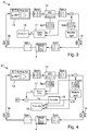
- FIG. 3 shows a block diagram of an electronics unit of the invention
- FIG. 4 shows a block diagram of a second embodiment of an electronics unit of the invention.
- FIG. 1 shows a vibronic fill-level measuring device 1 .
- the oscillatable unit 4 is excited by means of the excitation-/receiving unit 5 to execute mechanical oscillations, and can be, for example, a piezoelectric stack- or bimorph drive. Also other embodiments of a vibronic fill-level measuring device can be used.
- an electronics unit 6 is shown, which performs signal registration,—evaluation and/or—feeding.
- the excitation signal 7 for driving the oscillatable unit 4 is, according to the invention, composed of an excitation carrier signal 8 and an excitation modulation signal 9 , and is shown, by way of example, in FIG. 2 a as a function of time.
- the excitation modulation signal 9 with the excitation modulation frequency f M is visible as the envelope of the excitation carrier signal 8 with the excitation carrier frequency f C .
- the received signal 10 received from the oscillatable unit 4 is shown in FIG. 2 b together with the excitation signal 7 , likewise as a function of time.
- the received signal 10 is likewise composed of two parts, the received carrier signal 11 and the received modulation signal 12 .
- the received signal 10 has an amplitude different from the amplitude of the excitation signal 7 . Moreover, there occurs between the excitation signal 7 and the received signal 10 a phase shift, both with regard to the carrier signals ( 8 , 11 ) as well as also with regard to the modulation signals ( 9 , 12 ).
- D the damping
- ⁇ 0 the resonant frequency in the undamped case
- FIGS. 3 and 4 show, finally, two block diagrams with two possible embodiments for electronics units 6 ′ and 6 ′′ of the invention for a vibronic fill-level measuring device.
- the oscillatable unit 4 is excited by means of an electromechanical transducer unit 5 (not shown), which is part of a feedback, oscillatory circuit, for which the phase shift between the excitation carrier signal 8 and received carrier signal 10 is set by means of a filter (90°-filter) and an amplifier 13 and an automatic amplifier control (AGC) 14 .
- an electromechanical transducer unit 5 not shown
- AGC automatic amplifier control
- the frequency f C of the excitation carrier signal 8 respectively the carrier oscillation, (signal a) establishes itself within the oscillatory circuit in accordance with the oscillatory circuit condition. Modulated onto this signal is the excitation modulation signal 9 (signal b) with the excitation modulation frequency f M . From this there results the total excitation signal c, which is supplied to the oscillatable unit 4 after first passing through a digital-analog converter 15 . The received signal 10 (signal d) then received from the oscillatable unit 4 is identical with the excitation signal 7 (signal c) as regards carrier frequency f C and modulation frequency f M .
- the excitation signal 7 (signal c) and the received signal 10 (signal d) differ as regards amplitudes.
- phase shifts are present between the two signals, both with reference to the carrier signals 8 , 11 and with reference to the modulation signals 9 , 12 .
- the received signal 10 After passing through an analog-digital converter 16 , the received signal 10 (signal d) reaches the unit 13 composed of 90°-filter and amplifier.
- the phase shift of the resonance oscillation due to the carrier signal 8 , 11 is determined by the 90°-filter 13 and produces for resonance of the oscillatable unit 4 a phase shift of +90°.
- the much smaller modulation oscillation 9 , 12 is, however, not phase-shifted by the filter 13 .
- the received signal 10 (signal e) is then freed of the modulation oscillation 9 , 12 and becomes again the excitation carrier signal (signal a).
- the manipulated variable of the AGC 14 (signal f) comprises now exclusively the received modulation signal 12 (signal f).
- phase shift between the excitation modulation signal 9 (signal b) and the received modulation signal 12 (signal f) is ascertained by a phase meter 17 and fed to a phase evaluation unit 18 , which from the phase shift between the excitation modulation signal 9 (signal b) and the received modulation signal 12 (signal f) taking into consideration the excitation modulation frequency f M ascertains the damping, and from the damping, for example, the viscosity.
- a second variant for an electronics unit of the invention 6 ′′ is the subject matter of FIG. 4 .
- the oscillatory circuit for assuring resonant oscillations of the oscillatable unit 4 is unchanged, so that this aspect is not described again.
- the difference compared with FIG. 3 is that the excitation modulation frequency f M is now adjustable.
- the circuit frequencies ⁇ 0 and ⁇ M still enter into the evaluation.
- a phase shift between the excitation modulation signal 9 (signal b) and the received modulation signal 12 (signal f) of 45° leads to a simplified formula for the viscosity.
- phase control circuit 19 is provided, in order to obtain an adjustable, desired phase (45°).
- the excitation modulation frequency f M is set in such a manner that the phase shift between the excitation modulation signal 9 and the received modulation signal 11 amounts to 45°. From the measured resonant frequency ⁇ 0 , which corresponds to the excitation carrier frequency f C , and the set excitation modulation frequency ⁇ M, the damping is then obtained.
Landscapes
- Physics & Mathematics (AREA)
- General Physics & Mathematics (AREA)
- Immunology (AREA)
- Pathology (AREA)
- Analytical Chemistry (AREA)
- Biochemistry (AREA)
- General Health & Medical Sciences (AREA)
- Life Sciences & Earth Sciences (AREA)
- Health & Medical Sciences (AREA)
- Chemical & Material Sciences (AREA)
- Acoustics & Sound (AREA)
- Fluid Mechanics (AREA)
- Electromagnetism (AREA)
- Thermal Sciences (AREA)
- Engineering & Computer Science (AREA)
- Signal Processing (AREA)
- Measurement Of Levels Of Liquids Or Fluent Solid Materials (AREA)
- Measuring Volume Flow (AREA)
Abstract
Description
s1=ω0·(i√{square root over (1−D 2)}−D), s2=ω0·(−i√{square root over (1−D 2)}−D).
L(t)=AmpC·cos(ωC·t)·[(mo)·cos(ωM·t)+1]
wherein AmpC and ωC are the amplitude and the frequency of the carrier signal, and mo and ωM are the amplitude and the angular frequency of the modulation signal.
with
and the phase shift is
- 1 vibronic sensor
- 2 medium
- 3 container
- 4 oscillatable unit
- 5 electromechanical transducer unit
- 6 electronics unit
- 7 excitation signal
- 8 excitation carrier signal
- 9 excitation modulation signal
- 10 received signal
- 11 received carrier signal
- 12 received modulation signal
- 13 90°-filter and amplifier
- 14 AGC
- 15 D/A converter
- 16 A/D converter
- 17 phase meter
- 18 phase evaluation unit
- 19 phase control unit
- UE excitation signal
- UR received signal
- fC excitation carrier frequency
- fM excitation modulation frequency
- D damping
- ω0 resonant frequency of the undamped oscillator
- ωM frequency of the modulation
- ωC carrier frequency
- V amplification of the resonator at w=0
- AmpC excitation amplitude of the carrier frequency
- Mo modulation amplitude
Claims (15)
Applications Claiming Priority (4)
| Application Number | Priority Date | Filing Date | Title |
|---|---|---|---|
| DE102015101891.8 | 2015-02-10 | ||
| DE102015101891.8A DE102015101891A1 (en) | 2015-02-10 | 2015-02-10 | Device for determining and / or monitoring at least one process variable of a medium |
| DE102015101891 | 2015-02-10 | ||
| PCT/EP2016/051707 WO2016128217A1 (en) | 2015-02-10 | 2016-01-27 | Device for determining and/or monitoring at least one process variable for a medium |
Publications (2)
| Publication Number | Publication Date |
|---|---|
| US20180024097A1 US20180024097A1 (en) | 2018-01-25 |
| US10641736B2 true US10641736B2 (en) | 2020-05-05 |
Family
ID=55345802
Family Applications (1)
| Application Number | Title | Priority Date | Filing Date |
|---|---|---|---|
| US15/549,855 Active 2036-08-31 US10641736B2 (en) | 2015-02-10 | 2016-01-27 | Apparatus for determining and/or monitoring at least one process variable of a medium |
Country Status (5)
| Country | Link |
|---|---|
| US (1) | US10641736B2 (en) |
| EP (1) | EP3256822B1 (en) |
| CN (1) | CN107250760B (en) |
| DE (1) | DE102015101891A1 (en) |
| WO (1) | WO2016128217A1 (en) |
Families Citing this family (11)
| Publication number | Priority date | Publication date | Assignee | Title |
|---|---|---|---|---|
| DE102014119061A1 (en) * | 2014-12-18 | 2016-06-23 | Endress + Hauser Gmbh + Co. Kg | Vibronic sensor |
| DE102016112743A1 (en) | 2016-07-12 | 2018-01-18 | Endress+Hauser Gmbh+Co. Kg | Vibronic sensor |
| DE102016120326A1 (en) * | 2016-10-25 | 2018-04-26 | Endress+Hauser SE+Co. KG | Method for condition monitoring of an electromechanical resonator |
| GB2563192B (en) * | 2017-03-16 | 2021-02-24 | Rosemount Measurement Ltd | Improvements in or relating to vibrating element apparatus |
| EP3543660B1 (en) | 2018-03-22 | 2020-04-15 | VEGA Grieshaber KG | Impedance limit switch for reducing emi emissions and method for determining a limit level of a medium through an impedance limit switch |
| DE102018127526A1 (en) * | 2018-11-05 | 2020-05-07 | Endress+Hauser SE+Co. KG | Vibronic multi-sensor |
| DE102019116152A1 (en) * | 2019-06-13 | 2020-12-17 | Endress+Hauser SE+Co. KG | Vibronic multi-sensor |
| CA3205962A1 (en) * | 2019-08-20 | 2021-02-25 | Micro Motion, Inc. | Stabilized mode splitting fin sensor |
| CN114152541B (en) * | 2020-09-07 | 2024-11-19 | 中石化石油工程技术服务有限公司 | A tuning fork self-oscillating sensor system |
| DE102023110587A1 (en) | 2023-04-25 | 2024-10-31 | Endress+Hauser SE+Co. KG | measuring device |
| DE102024114994A1 (en) * | 2024-05-28 | 2025-12-04 | Vega Grieshaber Kg | Vibration sensor for level measurement and method for operating a vibration sensor |
Citations (19)
| Publication number | Priority date | Publication date | Assignee | Title |
|---|---|---|---|---|
| US4420983A (en) | 1980-02-28 | 1983-12-20 | The Marconi Company Limited | Mass flow measurement device |
| US5373745A (en) | 1991-02-05 | 1994-12-20 | Direct Measurement Corporation | Single path radial mode Coriolis mass flow rate meter |
| DE10050299A1 (en) | 2000-10-10 | 2002-04-11 | Endress Hauser Gmbh Co | Medium viscosity determination and monitoring arrangement has stimulation and reception unit, which excites vibrating unit and receives vibrations of vibrating unit for viscosity determination |
| DE10057974A1 (en) | 2000-11-22 | 2002-05-23 | Endress Hauser Gmbh Co | Determination of liquid level in a container or density of liquid in a container using a vibrating gimbal type body with compensation for temperature, pressure or viscosity variations to improve measurement accuracy |
| DE102004050494A1 (en) | 2004-10-15 | 2006-05-04 | Endress + Hauser Gmbh + Co. Kg | Device for determining and / or monitoring a process variable of a medium |
| US20060186897A1 (en) * | 2005-02-18 | 2006-08-24 | Markus Niemann | Method and device for detecting two parameters of a fluid |
| DE102005015547A1 (en) | 2005-04-04 | 2006-10-05 | Endress + Hauser Gmbh + Co. Kg | Medium e.g. liquid`s, process variable determining and monitoring device, has receiving unit converting oscillations to reception signals, and all-pass filter adjusting phase difference between excitation and reception signals |
| DE102006034105A1 (en) | 2006-07-20 | 2008-01-24 | Endress + Hauser Gmbh + Co. Kg | Device for determining and / or monitoring a process variable of a medium |
| DE102006033819A1 (en) | 2006-07-19 | 2008-01-24 | Endress + Hauser Gmbh + Co. Kg | Device for determining and / or monitoring a process variable of a medium |
| DE102007013557A1 (en) | 2006-08-02 | 2008-02-14 | Endress + Hauser Gmbh + Co. Kg | Device for determining and / or monitoring a process variable of a medium |
| DE102007043811A1 (en) | 2007-09-13 | 2009-03-19 | Endress + Hauser Gmbh + Co. Kg | Method for determining and / or monitoring the viscosity and corresponding device |
| US20100223019A1 (en) * | 2009-03-02 | 2010-09-02 | Karl Griessbaum | Measuring Filling Level by Means of Evaluating an Echo Curve |
| DE102009026685A1 (en) | 2009-06-03 | 2010-12-09 | Endress + Hauser Gmbh + Co. Kg | Method for determining or monitoring a predetermined level, a phase limit or the density of a medium |
| DE102009028022A1 (en) | 2009-07-27 | 2011-02-03 | Endress + Hauser Gmbh + Co. Kg | Method for determining and / or monitoring at least one physical process variable of a medium |
| US20110203388A1 (en) * | 2010-02-19 | 2011-08-25 | Hirokazu Kitami | Signal processing method, signal processing apparatus, and coriolis flowmeter |
| CN102177421A (en) | 2008-10-07 | 2011-09-07 | 恩德莱斯和豪瑟尔两合公司 | Device for determining and/or monitoring a process parameter of a medium |
| DE102010030982A1 (en) | 2010-07-06 | 2012-01-12 | Endress + Hauser Gmbh + Co. Kg | Method for controlling the phase in a resonant circuit |
| US20120174671A1 (en) * | 2009-09-30 | 2012-07-12 | Endress + Hauser Gmbh + Co. Kg | Method for determining and/or monitoring at least one physical, process variable |
| DE102011088351A1 (en) | 2011-12-13 | 2013-06-13 | Endress + Hauser Gmbh + Co. Kg | Device for determining and / or monitoring at least one process variable |
Family Cites Families (8)
| Publication number | Priority date | Publication date | Assignee | Title |
|---|---|---|---|---|
| JPH09107385A (en) * | 1995-10-11 | 1997-04-22 | Kyocera Corp | Phase detection method |
| DE10318445A1 (en) * | 2003-04-24 | 2004-11-11 | Endress + Hauser Gmbh + Co. Kg | Monitoring device for measuring and checking chemical and physical parameters of a process medium, has a checking device with which the operation of individual components can be checked |
| GB0417686D0 (en) * | 2004-08-09 | 2004-09-08 | Sensopad Ltd | Novel targets for inductive sensing applications |
| US8704533B2 (en) * | 2005-09-27 | 2014-04-22 | Ronald Quan | Method and apparatus to measure differential phase and frequency modulation distortions for audio equipment |
| JP4893170B2 (en) * | 2006-09-01 | 2012-03-07 | パナソニック株式会社 | Density sensor |
| CN102263717B (en) * | 2010-05-26 | 2014-03-12 | 北京创毅视讯科技有限公司 | Signal demodulating equipment and signal demodulating method |
| US8469891B2 (en) * | 2011-02-17 | 2013-06-25 | Siemens Medical Solutions Usa, Inc. | Viscoelasticity measurement using amplitude-phase modulated ultrasound wave |
| CN103344289B (en) * | 2013-07-03 | 2015-06-10 | 山东省科学院激光研究所 | Liquid flow non-immersive measuring device and sensing probe |
-
2015
- 2015-02-10 DE DE102015101891.8A patent/DE102015101891A1/en not_active Withdrawn
-
2016
- 2016-01-27 WO PCT/EP2016/051707 patent/WO2016128217A1/en not_active Ceased
- 2016-01-27 EP EP16703740.7A patent/EP3256822B1/en active Active
- 2016-01-27 CN CN201680009621.3A patent/CN107250760B/en active Active
- 2016-01-27 US US15/549,855 patent/US10641736B2/en active Active
Patent Citations (22)
| Publication number | Priority date | Publication date | Assignee | Title |
|---|---|---|---|---|
| US4420983A (en) | 1980-02-28 | 1983-12-20 | The Marconi Company Limited | Mass flow measurement device |
| US5373745A (en) | 1991-02-05 | 1994-12-20 | Direct Measurement Corporation | Single path radial mode Coriolis mass flow rate meter |
| DE10050299A1 (en) | 2000-10-10 | 2002-04-11 | Endress Hauser Gmbh Co | Medium viscosity determination and monitoring arrangement has stimulation and reception unit, which excites vibrating unit and receives vibrations of vibrating unit for viscosity determination |
| DE10057974A1 (en) | 2000-11-22 | 2002-05-23 | Endress Hauser Gmbh Co | Determination of liquid level in a container or density of liquid in a container using a vibrating gimbal type body with compensation for temperature, pressure or viscosity variations to improve measurement accuracy |
| DE102004050494A1 (en) | 2004-10-15 | 2006-05-04 | Endress + Hauser Gmbh + Co. Kg | Device for determining and / or monitoring a process variable of a medium |
| US20060186897A1 (en) * | 2005-02-18 | 2006-08-24 | Markus Niemann | Method and device for detecting two parameters of a fluid |
| DE102005007544A1 (en) | 2005-02-18 | 2006-08-24 | Robert Bosch Gmbh | Method and device for detecting two parameters of a fluid |
| US20090205411A1 (en) * | 2005-04-04 | 2009-08-20 | Endress + Hauser Gmbh + Co. Kg | Device for Determining and/or Monitoring a Process Variable of a Medium |
| DE102005015547A1 (en) | 2005-04-04 | 2006-10-05 | Endress + Hauser Gmbh + Co. Kg | Medium e.g. liquid`s, process variable determining and monitoring device, has receiving unit converting oscillations to reception signals, and all-pass filter adjusting phase difference between excitation and reception signals |
| DE102006033819A1 (en) | 2006-07-19 | 2008-01-24 | Endress + Hauser Gmbh + Co. Kg | Device for determining and / or monitoring a process variable of a medium |
| CN101517382A (en) | 2006-07-19 | 2009-08-26 | 恩德莱斯和豪瑟尔两合公司 | Sytem for determining and/or monitoring a process quantity of a medium |
| DE102006034105A1 (en) | 2006-07-20 | 2008-01-24 | Endress + Hauser Gmbh + Co. Kg | Device for determining and / or monitoring a process variable of a medium |
| DE102007013557A1 (en) | 2006-08-02 | 2008-02-14 | Endress + Hauser Gmbh + Co. Kg | Device for determining and / or monitoring a process variable of a medium |
| DE102007043811A1 (en) | 2007-09-13 | 2009-03-19 | Endress + Hauser Gmbh + Co. Kg | Method for determining and / or monitoring the viscosity and corresponding device |
| CN102177421A (en) | 2008-10-07 | 2011-09-07 | 恩德莱斯和豪瑟尔两合公司 | Device for determining and/or monitoring a process parameter of a medium |
| US20100223019A1 (en) * | 2009-03-02 | 2010-09-02 | Karl Griessbaum | Measuring Filling Level by Means of Evaluating an Echo Curve |
| DE102009026685A1 (en) | 2009-06-03 | 2010-12-09 | Endress + Hauser Gmbh + Co. Kg | Method for determining or monitoring a predetermined level, a phase limit or the density of a medium |
| DE102009028022A1 (en) | 2009-07-27 | 2011-02-03 | Endress + Hauser Gmbh + Co. Kg | Method for determining and / or monitoring at least one physical process variable of a medium |
| US20120174671A1 (en) * | 2009-09-30 | 2012-07-12 | Endress + Hauser Gmbh + Co. Kg | Method for determining and/or monitoring at least one physical, process variable |
| US20110203388A1 (en) * | 2010-02-19 | 2011-08-25 | Hirokazu Kitami | Signal processing method, signal processing apparatus, and coriolis flowmeter |
| DE102010030982A1 (en) | 2010-07-06 | 2012-01-12 | Endress + Hauser Gmbh + Co. Kg | Method for controlling the phase in a resonant circuit |
| DE102011088351A1 (en) | 2011-12-13 | 2013-06-13 | Endress + Hauser Gmbh + Co. Kg | Device for determining and / or monitoring at least one process variable |
Non-Patent Citations (1)
| Title |
|---|
| Search Report for International Patent Application No. PCT/EP2016/051707, WIPO, dated Jun. 30, 2016, 14 pp. |
Also Published As
| Publication number | Publication date |
|---|---|
| CN107250760A (en) | 2017-10-13 |
| CN107250760B (en) | 2021-03-02 |
| EP3256822B1 (en) | 2020-09-16 |
| US20180024097A1 (en) | 2018-01-25 |
| WO2016128217A1 (en) | 2016-08-18 |
| DE102015101891A1 (en) | 2016-08-11 |
| EP3256822A1 (en) | 2017-12-20 |
Similar Documents
| Publication | Publication Date | Title |
|---|---|---|
| US10641736B2 (en) | Apparatus for determining and/or monitoring at least one process variable of a medium | |
| US11073458B2 (en) | Vibronic sensor | |
| US10571380B2 (en) | Vibronic sensor | |
| US20200116545A1 (en) | Monitoring the condition of a vibronic sensor | |
| US10078005B2 (en) | Method for calibration or adjustment of any oscillatable unit | |
| US10928240B2 (en) | Vibronic sensor with interference compensation | |
| US10895489B2 (en) | Method for monitoring the condition of an electromechanical resonator | |
| EP2778609A1 (en) | Method for calibrating the scale factor of a hydraulic angular velocity sensor or axisymmetric vibratory gyroscope | |
| US20190339107A1 (en) | Vibronic sensor | |
| KR102302655B1 (en) | Controlling a vibration of a vibratory sensor based on a phase error | |
| CN111433573A (en) | Vibration sensor | |
| CN107003176A (en) | Electronic vibration sensor | |
| US10401215B2 (en) | Method and device for monitoring a process variable with vibronic sensor | |
| US11454531B2 (en) | Compensation of a phase shift of at least one component of an electronic system of a vibronic sensor | |
| US20170241954A1 (en) | Vibronic Sensor | |
| KR102135790B1 (en) | Determining a vibration response parameter of a vibratory element | |
| CN113728213B (en) | Monitoring the condition of vibration sensors | |
| US12281929B2 (en) | Vibronic sensor | |
| US12399055B2 (en) | Method for operating a vibronic sensor | |
| KR20180048787A (en) | Method for generating an output signal of a synthesis time period | |
| US12181316B2 (en) | Vibronic sensor | |
| DE102016124365A1 (en) | Vibronic sensor with temperature compensation |
Legal Events
| Date | Code | Title | Description |
|---|---|---|---|
| AS | Assignment |
Owner name: ENDRESS+HAUSER GMBH+CO. KG, GERMANY Free format text: ASSIGNMENT OF ASSIGNORS INTEREST;ASSIGNORS:D'ANGELICO, SASCHA;SCHMITT, CHRISTOPH;REEL/FRAME:043247/0110 Effective date: 20170620 |
|
| STPP | Information on status: patent application and granting procedure in general |
Free format text: DOCKETED NEW CASE - READY FOR EXAMINATION |
|
| AS | Assignment |
Owner name: ENDRESS+HAUSER SE+CO.KG, GERMANY Free format text: CHANGE OF NAME;ASSIGNOR:ENDRESS+HAUSER GMBH+CO. KG;REEL/FRAME:046443/0294 Effective date: 20180514 |
|
| STPP | Information on status: patent application and granting procedure in general |
Free format text: NON FINAL ACTION MAILED |
|
| STPP | Information on status: patent application and granting procedure in general |
Free format text: RESPONSE TO NON-FINAL OFFICE ACTION ENTERED AND FORWARDED TO EXAMINER |
|
| STPP | Information on status: patent application and granting procedure in general |
Free format text: FINAL REJECTION MAILED |
|
| STPP | Information on status: patent application and granting procedure in general |
Free format text: DOCKETED NEW CASE - READY FOR EXAMINATION |
|
| STPP | Information on status: patent application and granting procedure in general |
Free format text: NOTICE OF ALLOWANCE MAILED -- APPLICATION RECEIVED IN OFFICE OF PUBLICATIONS |
|
| STCF | Information on status: patent grant |
Free format text: PATENTED CASE |
|
| MAFP | Maintenance fee payment |
Free format text: PAYMENT OF MAINTENANCE FEE, 4TH YEAR, LARGE ENTITY (ORIGINAL EVENT CODE: M1551); ENTITY STATUS OF PATENT OWNER: LARGE ENTITY Year of fee payment: 4 |