US10640275B2 - Dual chamber storage device - Google Patents
Dual chamber storage device Download PDFInfo
- Publication number
- US10640275B2 US10640275B2 US16/006,283 US201816006283A US10640275B2 US 10640275 B2 US10640275 B2 US 10640275B2 US 201816006283 A US201816006283 A US 201816006283A US 10640275 B2 US10640275 B2 US 10640275B2
- Authority
- US
- United States
- Prior art keywords
- chamber
- cap
- hollow body
- storage device
- dispenser
- Prior art date
- Legal status (The legal status is an assumption and is not a legal conclusion. Google has not performed a legal analysis and makes no representation as to the accuracy of the status listed.)
- Active
Links
Images


Classifications
-
- B—PERFORMING OPERATIONS; TRANSPORTING
- B65—CONVEYING; PACKING; STORING; HANDLING THIN OR FILAMENTARY MATERIAL
- B65D—CONTAINERS FOR STORAGE OR TRANSPORT OF ARTICLES OR MATERIALS, e.g. BAGS, BARRELS, BOTTLES, BOXES, CANS, CARTONS, CRATES, DRUMS, JARS, TANKS, HOPPERS, FORWARDING CONTAINERS; ACCESSORIES, CLOSURES, OR FITTINGS THEREFOR; PACKAGING ELEMENTS; PACKAGES
- B65D81/00—Containers, packaging elements, or packages, for contents presenting particular transport or storage problems, or adapted to be used for non-packaging purposes after removal of contents
- B65D81/32—Containers, packaging elements, or packages, for contents presenting particular transport or storage problems, or adapted to be used for non-packaging purposes after removal of contents for packaging two or more different materials which must be maintained separate prior to use in admixture
- B65D81/3205—Separate rigid or semi-rigid containers joined to each other at their external surfaces
- B65D81/3211—Separate rigid or semi-rigid containers joined to each other at their external surfaces coaxially and provided with means facilitating admixture
Definitions
- One or more materials typically have to be mixed prior to use. Materials are often stored separately and then manually mixed prior to use. The process of accurately measuring, combining, and dispensing media can be susceptible to error. Therefore, it would be desirable to provide a device that holds materials separate and stable until time of use, while simultaneously providing a mechanism for combining the materials prior to dispensing the mixture or sampling the mixture by a machine or device.
- FIG. 1 is a perspective view of a dual chamber storage device according to an exemplary embodiment
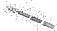
- FIG. 2 is an exploded perspective view of the dual chamber storage device shown in FIG. 1 ;
- FIG. 3 is a sectional perspective view of the dual chamber storage device shown in FIG. 1 ;
- FIG. 4A is a front view of a cap of the dual chamber storage device according to an exemplary embodiment
- FIG. 4B is a sectional view of the cap shown in FIG. 4A ;
- FIG. 5A is a front view of a second chamber of the dual chamber storage device according to an exemplary embodiment
- FIG. 5B is a sectional view of the second chamber shown in FIG. 5A ;
- FIG. 6A is a sectional view of a first chamber of the dual chamber storage device according to an exemplary embodiment
- FIG. 6B is an enlarged sectional view of the first chamber shown in FIG. 6A ;
- FIG. 7A is a front view of a dispenser of the dual chamber storage according to an exemplary embodiment.
- FIG. 7B is a sectional view of the dispenser shown in FIG. 7A ;
- FIG. 7C is an enlarged sectional view of the dispenser shown in FIG. 7B ;
- FIG. 8 is an enlarged sectional view of the cap shown in FIG. 4B ;
- FIG. 9 is a front view of a storage device according to another embodiment illustrated in an assembled configuration
- FIG. 10 is a front view of the storage device of FIG. 9 illustrated in a disassembled configuration
- FIG. 11 is a perspective view of a cap kit usable with the storage device of FIG. 9 according to an embodiment
- FIG. 12 is a sectional front view of the cap kit of FIG. 11 ;
- FIG. 13A is a front view of a first cap of the cap kit shown in FIG. 11 according to an embodiment
- FIGS. 13B and 13 C are each sectional front views of the first cap shown in FIG. 13A ;
- FIG. 14A is a front view of a second cap of the cap kit shown in FIG. 11 according to an embodiment.
- FIG. 14B is a sectional front view of the second cap shown in FIG. 14A .
- the present disclosure provides a dual chamber storage device 10 that stores a first material 28 and a second material 32 desired to be mixed together into a mixture prior to use. During storage, the first material 28 and the second material 32 remain separated.
- the dual chamber storage device 10 includes a first chamber 12 , a second chamber 14 , a dispenser 16 and a cap 20 .
- the first chamber 12 stores the first material 28 and the second chamber 14 stores the second material 32 .
- first material 28 is in one state whereas the second material 32 is in another state.
- first material 28 can be a solid whereas the second material 32 can be a liquid or a semi-solid.
- first material 28 can be a liquid whereas the second material 32 can be a solid or semi-solid.
- first material 28 can be a semi-solid whereas the second material 32 can be a solid or a liquid.
- first material 28 and the second material 32 are in the same state.
- both materials can be a liquid.
- both materials can be a semi-solid.
- Solid materials include but are not limited to powders, pellets, lyophilized materials.
- Liquid materials include but are not limited to water, alcohol, solvents.
- the first material 28 is present in a predetermined amount and the second material 32 is present in a predetermined amount.
- the first chamber 12 includes a hollow body 26 that stores the first material 28 .
- the first chamber 12 is also generally non-deformable, such that the size and shape of the first chamber 12 remains substantially fixed during use of the device 10 .
- the first chamber 12 can be made of a material to have a sufficient thickness and rigidity so as to be generally non-deformable but capable of being squeezed.
- the second chamber 14 also includes a hollow body 30 that stores second material 32 .
- the second chamber 14 can transform between a deformed state and a non-deformed state. In the non-deformed state, the second chamber 14 is not deformed and the first material 28 in the first chamber 12 is separated from the second material 32 in the second chamber 14 . The first material 28 and the second material 32 even remain separated when the device 10 is inverted or shaken.
- the second chamber 14 includes a portion that is deformed such that the second material 32 enters into the first chamber 12 and mixes with the first material 28 to form a mixture. The mixture can then pass back and forth through the first chamber 12 and the second chamber 14 and out of the device through the dispenser 16 .
- the deformable portion can be any component of the second chamber 14 that can be deformed to allow the second material 32 to enter into the first chamber 12 .
- the deformable portion is a deformable base 27 .
- the deformable base 27 comprises a material that can be deformed by cutting or piercing.
- the base 27 comprises a deformable material whereas the remaining components of the second chamber 14 comprises a non-deformable material.
- the dispenser 16 includes a deforming structure that is capable of deforming the deformable portion of the second chamber 14 .
- the deforming structure cuts or pierces or otherwise deforms the deformable portion.
- the deforming structure is a deforming edge 48 .
- the dispenser 16 also includes a dispensing tip 42 for controlling delivery of a mixture of the first material 28 and the second material 32 .
- the device 10 also includes a cap 20 configured substantially surround an upper portion of the device 10 so as to isolate the device 10 from moisture, dust and other extraneous particles, thereby ensuring product stability.
- the device 10 can also have one or more fluid-tight seals to reduce or substantially prevent moisture or particle intrusion into the device prior to use. Such fluid-tight seals can also help reduce leakage of materials from the device 10 .
- the dispenser 16 When it is desired to mix the first material 28 with the second material 32 , a user exerts force on the dispenser 16 to cause the deforming structure to deform the deformable portion of the second chamber 14 . Once the second chamber 14 is deformed, the second material 32 in the second chamber 14 moves through the deformed portion to mix with the first material 28 in the first chamber 12 . The mixture can also freely travel through the first chamber 12 , the second chamber 14 and the dispenser 16 , ultimately leaving the device 10 via the dispensing tip 42 of the dispenser 16 .
- FIGS. 1-3 illustrate components of the device 10 .
- the components can be connected together to protect the first material 26 and the second material 32 during non-use.
- the first chamber 12 and the cap 20 are connected together so as to substantially surround and isolate the second chamber 14 and the dispenser 16 from an outside environment.
- the second chamber 14 can be nested coaxially within the first chamber 12
- the dispenser 16 can be nested coaxially within the second chamber 14 .
- the first chamber 12 has an internal perimeter IP 1 and an external perimeter EP 1
- the second chamber 14 has an internal perimeter IP 2 and an external perimeter EP 2
- the dispenser 16 has an internal perimeter IP 3 and an external perimeter EP 3
- the cap 20 has an internal perimeter IP 5 and an external perimeter EP 5 .
- the IP 1 is larger than the EP 2 and IP 2 is larger than EP 3 .
- the IP 1 substantially surrounds the EP 2 and the IP 2 substantially surrounds the EP 3 .
- Such perimeter relationships allow the second chamber 14 to be nested coaxially within the first chamber 12 and the dispenser 16 to be nested coaxially within the second chamber 14 .
- the cap 20 can substantially surround both the dispenser 16 and the second chamber 14 .
- the IP 4 is larger than the EP 3 and the EP 2 .
- This perimeter relationship allows the cap to substantially surround both the dispenser 16 and the second chamber 14 .
- the cap 20 can have an exterior perimeter EP 5 that substantially matches or matches the exterior perimeter EP 1 first chamber 12 . In such cases, the EP 5 is substantially close to or substantially the same as the EP 1 . This allows for the cap 20 and first chamber 12 to connect together and substantially surround and isolate the second chamber 14 and the dispenser 16 from an outside environment.
- the dual chamber storage device 10 has a first chamber 12 as shown in FIGS. 6A and 6B .
- the first chamber 12 includes a hollow body 26 that stores a first material 28 . In some cases, the entire first chamber 12 is configured to be a hollow body 26 .
- the first chamber 12 has a first end 59 and a second end 60 .
- the first end 59 is opposite the second end 60 .
- the first end 59 includes a base 24 that engages with a support surface. In the illustrated embodiment, a bottom edge of the first end 59 is configured as a base 24 .
- the 24 base can be generally planar so as to rest on a generally planar support surface such as a table or shelf.
- the first chamber 12 also includes a first chamber neck portion 70 proximal to the second end 60 .
- FIG. 6B perhaps best illustrates the first chamber neck portion 70 .
- the first chamber 12 also includes a sealing portion 72 , which forms a seal 76 with the second chamber 14 when the second chamber 14 is nested within the first chamber 12 .
- the first chamber neck portion 70 includes the sealing portion 72 , which can be formed on an interior surface of the first chamber neck portion 70 .
- the sealing portion 72 spans an entire interior perimeter IP 1 of the first chamber neck portion 70 .
- the sealing portion 72 includes a groove.
- the first chamber neck portion 70 includes an anti-rotation groove 71 that can include a plurality of ribs 78 . In some cases, the plurality of ribs 78 can be evenly spaced. Ribs 78 prevent chamber 14 from rotating inside chamber 12 .
- the first chamber 12 has a cylindrical shape, though other shapes can be used instead.
- the first chamber 12 is also generally non-deformable, such that the size and shape of the first chamber 12 remains substantially fixed during use of the device 10 .
- the first chamber 12 can be made of a material having a sufficient thickness and rigidity so as to be generally non-deformable but capable of being squeezed.
- the first chamber 12 comprises a polymer.
- the polymer can be a low density polyethylene.
- the polymer can be a polyethylene or polypropylene, though other suitable materials can be used instead.
- the first chamber 12 may be sized so as to hold a small dosage of a material. Accordingly, in certain non-limiting examples, the first chamber 12 has a diameter of between about 0.25 inches and about 1 inch, for instance, about 0.75 inches. Further, the first chamber 12 can have a height of between about 1 inch and about 3 inches, for example, about 1.5 inches. In some such embodiments, the first chamber 12 may hold a volume of a material between about 1 microliter and about 5 milliliters. In addition, the size of the first chamber 12 can be adjusted so as to maintain a specific component ratio between the first material 28 , and a second material 32 stored in the second chamber 14 .
- the device 10 has a second chamber 14 as shown in FIGS. 5A and 5B .
- the second chamber 14 also includes a hollow body 30 that stores the second material 32 .
- the entire second chamber 14 is configured to be a hollow body.
- the second chamber 14 also has a first end 29 and a second end 31 .
- the first end 29 is opposite the second end 31 .
- the second chamber 14 includes a second chamber neck portion 34 proximal to the second end 31 .
- the second chamber 14 also includes an anti-rotation bead 73 , a sealing portion 74 and a sealing portion 82 .
- the second chamber 14 attaches to the first chamber 12 .
- the second chamber 14 fixedly attaches to the first chamber 12 such that the second chamber 14 does not move relative to the first chamber 12 .
- the second chamber 14 attaches to the first chamber 12 using a snap-fit connection mechanism.
- a variety of snap-fit connection mechanisms are known in the art and can be used.
- the second chamber 14 nests within the first chamber 12 .
- the second chamber 14 includes a sealing portion 74 which engages with the sealing portion 72 of the first chamber 12 to form a seal 76 (e.g., as seen in FIG. 3 ).
- the sealing portion 74 is formed on an exterior surface of the second chamber 14 .
- the sealing portion 74 spans an entire exterior perimeter EP 2 of the second chamber 14 .
- the sealing portion 74 includes a bead that engages with a groove of the sealing portion 72 of the first chamber 12 to form the seal 76 .
- the second chamber 14 also includes an anti-rotation bead 73 , which fits within the anti-rotation groove 71 of the first chamber 12 .
- the one or more ribs 78 in the anti-rotation groove 71 allow for a snap-fit of the anti-rotation bead 73 within the anti-rotation groove 71 . This prevents chamber 14 from rotating inside chamber 12 .
- a portion of anti-rotation bead 73 can be removed to improve engagement of the anti-rotation bead 73 with the anti-rotation groove 71 .
- the second chamber 14 includes an additional sealing portion 82 which forms a seal 86 with the dispenser 16 when the second chamber 14 is in the deformed state.
- the second chamber 14 also includes an additional sealing portion 83 , which forms the seal 86 with dispenser 16 when the second chamber 14 is not in the deformed state.
- the second chamber neck portion 34 includes the sealing portion 82 , which can be formed on an interior surface of the second chamber neck portion 34 .
- the sealing portion 82 spans an entire interior perimeter of the second chamber neck portion 34 .
- the sealing portion 82 includes a groove.
- the second chamber neck portion 34 also includes a second chamber threaded portion 54 .
- the second chamber threaded portion 54 is formed on an exterior surface of the neck portion 34 , as best shown in FIG. 5A .
- the threaded portion 54 spans an entire exterior perimeter EP 2 of the second chamber 14 .
- the second chamber 14 also has a cylindrical shape, though other shapes are contemplated.
- the second chamber 14 also comprises a polymer.
- the polymer can be a low density polyethylene.
- the polymer can be a polyethylene or polypropylene, though other suitable materials can be used instead.
- the second chamber 14 also includes a deformable portion.
- the deformable portion is a deformable base.
- the deformable base comprises a material than can be deformed by cutting or piercing.
- the deformable base is a base 27 positioned proximal to the first end 29 , as best shown in FIG. 5B .
- the deformable base 27 is positioned above a bottom edge 33 of the second chamber 14 .
- the deformable base 27 is positioned inside of the second chamber 14 .
- the deformable base comprises a deformable material whereas the remaining components of the second chamber 14 comprise a non-deformable material.
- the deformable base can comprise a foil seal whereas the remaining components comprises a polymer.
- the polymer can be a low density polyethylene. In other cases, the polymer can be a polyethylene or polypropylene, though other suitable materials can be used instead.
- both the deformable base and the remaining components are of the same material but have differing thicknesses.
- the deformable base and the remaining components can both comprise a polymer, such as a low density polyethylene.
- the deformable base has a thickness small enough that enables the base to easily be deformed by cutting or piercing, whereas the remaining components have a thickness large enough that renders the components non-deformable.
- the deformable base can have a thickness between about 0.010 inches and 0.03 inches.
- the remaining components can have a thickness between about 0.015 inches and 0.04 inches.
- the second chamber 14 comprises a vent 80 disposed outside of the hollow body of the second chamber 14 .
- the vent 80 in the illustrated example, is positioned below the first seal 76 , such that the vent 80 may permit venting of the first chamber 12 while simultaneously fluidly isolating the first material 28 from the second material 32 .
- the vent 80 permits venting of the first chamber 12 during lyophilization.
- the device 10 also includes a dispenser 16 as shown in FIGS. 7A, 7B and 7C .
- the dispenser 16 includes a hollow body 36 and a first end 40 and a second end 38 .
- the first end 40 is opposite the second end 38 .
- the first end 40 includes a deforming structure 46 that is capable of deforming the deformable base of the second chamber 14 .
- the second end 38 includes a dispensing tip 42 for controlling delivery of a mixture of the first material 28 and the second material 32 .
- the dispenser 16 also includes a sealing portion 84 and a sealing portion 104 .
- the dispenser 16 can comprise a polymer. In certain cases, the polymer can be a polystyrene. In other cases, the polymer can be a polyethylene or polypropylene, though other suitable materials can be used instead.
- the deforming structure 46 is a deforming edge 48 capable of deforming the base.
- the deforming edge 48 cuts or pierces the base.
- the deforming edge 48 can be at an angle of 3° to 15° and can either be smooth yet sharp, or optionally include serrations 6 .
- FIG. 3 the deforming edge 48 is illustrated without serrations 6
- FIG. 2 the deforming edge 48 is illustrated with serrations 6 .
- the deforming edge 48 as seen from FIGS. 2 and 3 , comprises a cutting edge perimeter (best seen in FIG. 7A ).
- the serrations 6 are provided throughout the perimeter of the deforming edge 48 .
- the dispenser 16 attaches to the second chamber 14 .
- the dispenser 16 attaches to the second chamber 14 using a snap-fit connection mechanism.
- a variety of snap-fit connection mechanisms are known in the art and can be used.
- the dispenser 16 has a sealing portion 84 that engages with the sealing portion 82 of the second chamber 14 to form a seal 86 when the second chamber 14 is in the deformed state.
- the sealing portion 84 engages with the sealing portion 83 of the second chamber 14 to form the seal 86 when the second chamber 14 is not in the deformed state (e.g., as seen in FIG. 3 ).
- the sealing portion 84 is formed on an exterior surface of the dispenser 16 .
- the sealing portion 84 spans an entire exterior perimeter EP 3 of the dispenser 16 .
- the sealing portion 84 includes a bead that engages with the groove of the sealing portion 82 of the second chamber 14 to form the seal 86 .
- the one or more ribs can be provided in the groove allow for a snap-fit of the bead within the groove. Referencing FIG. 3 , the seal 86 is axially offset from the seal 76 .
- the dispenser 16 also includes a dispensing tip 42 , which can be sized and shaped to deliver a precise amount of the mixture.
- the dispensing tip 42 is sized and shaped to deliver a mixture in an amount of between about 1 microliters and 100 microliters, for instance about 20 microliters.
- FIG. 7C shows an enlarged sectional view of the dispensing tip 42 .
- the dispensing tip 42 has a generally tapered body portion 92 terminating in an aperture 94 .
- the aperture 94 is in fluid communication with the hollow body 36 of the dispenser 16 and permits a mixture to flow through.
- the dispensing tip 42 has a top surface 96 and the aperture 94 is recessed from the top surface 96 . Such embodiment can be beneficial in reducing leakage during use while also providing a precise dose corresponding to the size and shape of the dispensing tip 42 .
- the aperture 94 is generally cylindrical in shape and has a diameter of between about 0.01 inches and about 0.5 inches. In some such examples, the aperture 94 has a diameter of about 0.025 inches.
- the generally tapered body portion 92 can have a taper angle 98 , defined relative to a central axis of the dispenser 16 of between about 5 degrees and about 30 degrees. In certain examples, the taper angle 98 can be about 10 degrees.
- the dispenser 16 also includes a sealing portion 104 provided along the generally tapered body portion 92 of the dispensing tip 42 .
- the sealing portion 104 engages with a sealing portion 106 of the cap 20 to form a seal 108 (e.g., as seen in FIG. 3 ).
- the sealing portion 104 is formed on an exterior surface of the dispensing tip 42 .
- the sealing portion 104 spans an entire exterior perimeter EP 4 of the dispensing tip 42 .
- the sealing portion 104 includes a bead that contacts the top of a bead in the sealing portion 106 of the cap 20 to form the seal 108 .
- the dispenser 16 is movable relative to the second chamber 14 .
- the dispenser 12 is movable towards the second chamber 14 .
- the device 10 also includes a cap 20 that substantially surrounds an upper portion of the device 10 so as to isolate the device 10 from moisture, dust and other extraneous particles, thereby ensuring product stability.
- the cap 20 can also be made of a material such as high density polyethylene or polypropylene, though other materials are contemplated within the scope of the present disclosure.
- FIGS. 4A and 4B illustrate an exemplary embodiment of the cap 20 .
- the cap 20 comprises a threaded portion 50 .
- the threaded portion 50 is formed on an interior surface of the cap 20 .
- the threaded portion 50 spans an entire interior surface of the cap 20 .
- the threaded portion 50 spans an entire interior perimeter IP 5 of the cap 20 .
- the cap 20 also includes a bottom edge 66 , which is the lowermost boundary of the cap 20 .
- the cap includes a generally planar top surface 100 positionable to be in contact with the generally planar top surface 90 of the dispenser 16 . Referring now to FIG.
- the cap 20 includes a tapered portion 102 positioned above the generally planar top surface 100 of the cap 20 .
- the tapered portion 102 of the cap 20 is sized and shaped to generally match the size and shape of the tapered body portion 92 of the dispensing tip 42 .
- the cap 20 attaches to the dispenser 16 .
- the cap 20 is fixedly and/or rigidly and/or non-rotatingly attachable to the dispenser 16 .
- the cap 20 attaches to a second end 38 of the dispenser 16 .
- the cap 20 fixedly and/or rigidly and/or non-rotatingly attaches to the second end 38 .
- the cap 20 also attaches to the second chamber 14 .
- the cap 20 is rotatingly attachable to the second chamber 14 .
- the cap 20 is attachable to a second end 34 of the second chamber 14 .
- the cap 20 is rotatably attachable to the second end 34 .
- the threaded portion 50 of the cap 20 threads or screws around the threaded portion 54 of the second chamber 14 .
- the threaded portion 54 is a male portion that threads or screws into the threaded portion 50 , which is a female portion.
- the threaded portion 50 can be a male portion that threads into a female threaded portion 54 .
- the cap 20 has a sealing portion 106 that engages with a sealing portion 104 of the dispenser 16 to form a seal 108 . As shown in FIG. 8 , the sealing portion 106 is formed on an interior surface of the cap 20 .
- the cap 20 is rotatingly attachable with the second end 34 of the second chamber 14 while being fixedly attachable to the second end 38 of the dispenser such that when the cap 20 is rotated relative to the second chamber neck portion 34 , the cap 20 does not rotate with respect to the first end 38 of the dispenser 16 .
- a force/torque is exerted on the second end 38 of the dispenser 16 , thereby causing the first end 40 and thus the deforming structure 46 to move toward the base of the second chamber 14 .
- the deforming structure 46 contacts the base 27 , it deforms the base 27 , thereby allowing the second material 32 to enter the first chamber 12 .
- the device 10 can also include a tamper evident ring 62 positioned between the cap 20 and the first chamber 12 .
- the tamper evident ring 62 can be a “warranty seal” to a user. For example, if the tamper evident ring 62 is present, a user can assume that the device 10 has not been used and thus the first material 28 in the first chamber 12 and the second material 32 in the second chamber 14 have not been mixed. However, if the tamper evident ring 62 is not present, a user can assume the device 10 has been tampered or used and thus the first material 28 and the second material 32 may have been mixed.
- the tamper evident ring 62 can include a top edge 64 and a bottom edge 66 .
- the top edge 64 of the tamper evident ring 62 is positioned so as to abut the bottom edge 58 of the cap 20
- the bottom edge 66 of the tamper evident ring 62 is positioned so as to abut the top edge 60 of the first chamber 12 .
- the cap 20 is not rotatable relative to the second chamber neck portion 34 .
- the cap 20 is rotatable relative to the second chamber neck portion 34 .
- the user removes the tamper evident ring 62 prior to rotatingly engaging the first threaded portion 50 and the second threaded portion 54 .
- FIGS. 9-14B illustrate the device according to another embodiment.
- the device may include a cap kit 200 connectable with a first container 202 , and a second container 204 .
- the first container 202 can be substantially similar to the first chamber 12 .
- the first container 202 can be substantially different from the first chamber 12 .
- the first container 202 can be an off-the-shelf component, such as a vial.
- the first container 202 can be made from many different types of materials, such as glass, polymer, etc.
- the first container 202 can store the first material 28 .
- the cap kit 200 can include a first cap 210 .
- the first cap 210 can engage with the first container 202 .
- the first cap 210 can include threads (best seen in FIG. 12 ).
- the threads of the first cap 210 are defined on an interior surface of the first cap 210 .
- the first container 202 can have corresponding threads on an exterior surface of the first container 202 . Accordingly, the threads of the first cap 210 can engage with the threads of the first container 202 .
- Alternative types of connections (such as threads other than those illustrated, frictional engagement, snap-fit, and the like) are contemplated within the scope of this disclosure.
- the first cap 210 can be made of a polymer such as polypropylene, although other materials are contemplated within the scope of the present disclosure.
- the first cap 210 can be made by a process such as injection molding, though, other processes (including additive manufacturing) are contemplated within the scope of the present disclosure.
- the surfaces of the first cap 210 can have a desired finish, for instance, an SPI Finish designation such as a D-1 (e.g., dry blast of a suitable size) finish.
- the finish of the surfaces of the first cap 210 can be different in certain portions of the second cap 212 .
- interior surfaces of the first cap engagement portion 216 and/or the first cap ring portion 230 can have a different surface finish (e.g., an SPI finish designation such as A-3 or better).
- the cap kit 200 can also include a second cap 212 .
- the second cap 212 can be engaged with a second container 204 .
- the second container 204 can be substantially similar to the second chamber 14 .
- the second container 204 can be substantially different from the second chamber 14 .
- the second container 204 can be an off-the-shelf component such as a vial or a micro-tube.
- the second container 204 can be made from many different types of materials, such as glass, polymer, etc.
- the second container 204 can store the second material 32 .
- the second cap 212 can engage with the second container 204 .
- the second cap 212 can include threads to engage with the second container 204 .
- the threads of the second cap 212 are defined on an interior surface of the second cap 212 .
- the second container 204 can have corresponding threads on an exterior surface of the second container 204 . Accordingly, the threads of the second cap 212 can engage with the threads of the second container 204 .
- Alternative types of connections (such as threads other than those illustrated, frictional engagement, snap-fit, and the like) are contemplated within the scope of this disclosure.
- the second cap 212 can be made of a polymer such as low density polyethylene, although other materials are contemplated within the scope of the present disclosure.
- the second cap 212 be made by a process such as molding, though, other processes (including additive manufacturing) are contemplated within the scope of the present disclosure.
- the surfaces of the second cap 212 can have a desired finish, for instance, an SPI Finish designation such as a D-1 finish.
- the finish of the surfaces of the second cap 212 can be different in certain portions of the second cap 212 .
- exterior surfaces of the second cap engagement portion 266 can have a different surface finish (e.g., an SPI finish designation such as A-3 or better).
- the entirety of the first cap 210 and the second cap 212 can have substantially the same finish to facilitate ease of manufacturing and reduce cost of fabricating the cap kit.
- the first cap 210 and the second cap 212 or portions thereof can have different surface finishes.
- the first cap 210 and the second cap 212 can form the cap kit 200 for use with off-the-shelf containers such as vials, micro-tubes, and the like.
- a user can connect the first container 202 having the first material 28 (e.g., lyophilized powder sealed in the first container 202 ) to the first cap 210 and connect the second container 204 (e.g., micro-tube having the second material 32 ) to the second container 204 .
- the first and second materials 28 and 32 can be protected by the cap kit prior to use.
- Such embodiments can provide an easy to use cap kit for engaging with different types of containers.
- the first cap 210 can receive and surround the first container 202 to enclose and protect the contents (e.g., the first material 28 ) of the first container 202 .
- the second cap 212 substantially surrounds the second container 204 to enclose and protect the contents (e.g., the second material 32 ) of the second container 204 .
- the first cap 210 can receive and surround the second cap 212 .
- FIGS. 11, 12, and 13A -C illustrate various views of the first cap 210 according to an embodiment.
- the first cap 210 has a first cap base portion 214 and a first cap engagement portion 216 .
- the first cap base portion 214 and the first cap engagement portion 216 each have a circular cross-section. However, other cross-sectional shapes can be contemplated.
- the first cap base portion 214 has a first cap base portion diameter 218 and a first cap base portion height 220 .
- the first cap base portion diameter 218 can be suitably chosen to engage with any commercially available first container 202 .
- the first cap base portion 214 can include threads 222 to engage with the first container 202 (e.g., vials of different sizes).
- the threads can be of a suitable pitch and type to engage with any commercially available first container 202 (e.g., vials of different sizes).
- the threads may be located on an interior surface 224 of the first cap base portion 214 , and may start at a first distance 226 from an edge 228 of the first cap base portion 214 .
- the first cap 210 can also include a first cap ring portion 230 .
- the first cap ring portion 230 can be detachably coupled to the first cap engagement portion 216 .
- the first cap ring portion 230 can have an outer edge 232 and an inner edge 234 .
- the outer edge 232 can be an outermost edge of the first cap ring portion 230 and the inner edge 234 can be an innermost edge of the first cap ring portion 230 .
- the inner edge 234 of the first cap ring portion 230 can be closer to an outer edge 236 of the first cap engagement portion 216 than the outer edge 232 of the first cap ring portion 230 .
- the outer edge 236 of the first cap engagement portion 216 can be an outermost edge. For example, as seen in FIGS.
- the first cap 210 can include a plurality of tabs 240 defined on the inner edge of the first cap ring portion 230 and/or outer edge of the first cap engagement portion 216 to engage the first cap ring portion 230 to the first cap engagement portion 216 .
- the first cap ring portion 230 can include a tearing tab 242 .
- the tearing tab 242 can be grasped and pulled circumferentially, thereby tearing the first cap ring portion 230 from the first cap engagement portion 216 .
- the first cap engagement portion 216 includes a first groove 244 and a second groove 246 in some embodiments.
- the first groove 244 and the second groove 246 can be defined on an interior surface 248 of the first cap engagement portion 216 .
- the first groove 244 can be axially spaced apart from the second groove 246 , along a first cap center axis 250 .
- the first groove 244 can be an outermost groove and positioned further away from the first cap base portion 214 than the second groove 246 .
- the second groove 246 can be an innermost groove and can be positioned closer to the first cap base portion 214 than the first groove 244 .
- the first groove 244 and the second groove 246 can each have a groove diameter 254 .
- the groove diameter 254 can be larger than a nominal diameter 252 of the interior surface 248 of the first cap engagement portion 216 .
- the first cap 210 includes a piercing protrusion 260 .
- the piercing protrusion 260 can extend from the first cap base portion 214 .
- the piercing protrusion 260 can be housed within the first cap engagement portion 216 .
- the piercing protrusion 260 can project past the second groove 246 .
- the piercing protrusion 260 can have a piercing protrusion height 262 .
- the piercing protrusion 260 can be coaxial with the first cap base portion 214 and/or the first cap engagement portion 216 .
- the piercing protrusion 260 can be centered on the first cap center axis 250 .
- the piercing protrusion 260 can be off-axis with the first cap center axis 250 in other embodiments.
- FIGS. 9-12, 14A, and 14B illustrate various views of the second cap 212 according to an embodiment.
- the second cap 212 has a second cap base portion 264 and a second cap engagement portion 266 .
- the second cap base portion 264 and the second cap engagement portion 266 each have a circular cross-section.
- other cross-sectional shapes can be contemplated.
- the second cap base portion 264 has a second cap base portion diameter 268 and a second cap base portion height 270 .
- the second cap base portion diameter 268 can be suitably chosen to engage with any commercially available second container 204 .
- the second cap base portion 264 can include threads 272 to engage with the second container 204 (e.g., vials, micro-tubes of different sizes).
- the threads can be of a suitable pitch and type to engage with any commercially available second container 204 (e.g., vials, micro-tubes of different sizes).
- the threads may be located on an interior surface 274 of the second cap base portion 264 , and may start at a second distance 276 from an edge 278 of the second cap base portion 264 .
- the second cap engagement portion 266 includes a first rib 280 and a second rib 282 in some embodiments.
- the first rib 280 and the second rib 282 can be defined on an exterior surface 284 of the second cap engagement portion 266 .
- the first rib 280 can be axially spaced apart from the second rib 282 , along a second cap center axis 286 .
- the first rib 280 can be an outermost rib and positioned further away from the second cap base portion 264 than the second rib 282 .
- the second rib 282 can be an innermost rib and can be positioned closer to the second cap base portion 264 than the first rib 280 .
- the first rib 280 and the second rib 282 can each have a rib diameter 288 .
- the rib diameter 288 can be larger than a nominal diameter 290 of the exterior surface 284 of the second cap engagement portion 266 .
- the second cap 212 includes a protective surface 292 .
- the protective surface 292 can, in some embodiments, form an outermost surface of the second cap 212 in the axial direction. In some such cases, the protective surface 292 can be in the form of a membrane.
- the protective surface 292 can be substantially flexible relative to the second cap base portion 264 and/or second cap engagement portion 266 . In one example, the protective surface 292 can be made of the same material as the second cap 212 . In such cases, the protective surface 292 can have a thickness substantially less than the thickness of a portion of the second cap 212 . For example, the protective surface 292 can have a thickness substantially less than the thickness of the lateral portion 300 of the second cap 212 .
- the protective surface 292 can be deformable (e.g., pierced/torn, etc.)
- the protective surface 292 can be made of a different material (e.g., more deformable/flexible material) from the material of the second cap 212 .
- the thickness of the protective surface 292 may not be uniform.
- the protective surface 292 can have an outer portion 294 and an inner portion 296 .
- the outer portion 294 of the protective surface 292 can attach to the lateral portion 300 of the second cap 212 .
- the outer portion 294 can be radially further outward than the inner portion 296 .
- the outer portion 294 can extend radially over an outer radial distance 302
- the inner portion 296 can extend radially over an inner radial distance 304 .
- the inner radial distance 304 is greater than the outer radial distance 302 .
- the outer radial distance 302 can be such that the outer portion 294 at least partially radially overlaps with of the piercing protrusion 260 (best seen in FIGS. 13B and 13C ). However, the outer radial distance 302 can be greater than the inner radial distance 304 in alternative embodiments.
- the outer portion 294 can have an outer portion thickness 310 and the inner portion 296 can have an inner portion thickness 312 .
- the outer portion thickness 310 can be less than the inner portion thickness 312 , to facilitate ease of deformation of the protective surface 292 .
- the outer portion thickness 310 and the inner portion thickness 312 can be substantially the same.
- the first cap 210 and the second cap 212 can be engaged with each other in a first position.
- the first cap base portion 214 is oriented generally opposite to the second cap base portion 264 .
- the first cap base portion 214 can have an outer edge 265 and the second cap base portion 264 can have an outer edge 267 .
- the outer edges 265 , 267 of the first cap base portion 214 and the second cap base portion 264 can each be the outermost edges of the first cap base portion 214 and the second cap base portion 264 respectively.
- the outer edges 265 , 267 of the first cap base portion 214 and the second cap base portion 264 can be opposite to each other along the central axis.
- first rib 280 is received within the first groove 244 .
- the outer edge of the first cap ring portion 230 abuts the outer edge of the second cap base portion 264 .
- the inner edge of the first cap ring portion 230 abuts the outer edge of the first cap engagement portion 216 .
- the protective surface 292 can be opposite to the piercing protrusion 260 .
- the protective surface 292 can be spaced apart from the piercing protrusion 260 such that the protective surface 292 is not deformed.
- the second material 32 can be protected and enclosed within the second container 204 .
- the second cap 212 can be movable (slidable along the central axis and/or rotationally about the central axis) with respect to the first cap 210 to deform (e.g., pierce or tear) the protective surface 292 .
- the second cap 212 can be movable with respect to the first cap 210 , when the first cap ring portion 230 is detached from the first cap engagement portion 216 . Once the first cap ring portion 230 is removed, the second cap 212 can be moved with respect to the first cap 210 , such that the outer edge of the second cap base portion 264 can abut the outer edge of the first cap engagement portion 216 .
- the first rib 280 can engage with the second groove 246
- the second rib 282 can engage with the first groove 244 .
- the piercing protrusion 260 can abut and deform the outer portion 294 of the protective surface 292 .
- the second material 32 can be received within the first material 28 (e.g., by gravity or by shaking the first and/or second containers).
- the device can be inverted to receive the first material 28 in the second container 204 in other embodiments.
- the protective surface 292 may not be deformed, and the outer edge 232 of the first cap ring portion 230 can abut the outer edge 267 of the second cap base portion 264 .
- a user may grasp and pull the tearing tab 242 of the first cap ring portion 230 .
- the first cap ring portion 230 may be detached from the first cap engagement portion 216 .
- the second cap 212 can be pushed such that the outer edge 267 of the second cap base portion 264 abuts the outer edge 236 of the first cap engagement portion 216 .
- the first rib 280 can engage with the second groove 246
- the second rib 282 can engage with the first groove 244
- the piercing protrusion 260 can pierce the protective surface 292 .
- the first and second material 32 can be mixed.
- the user may, optionally, remove the first cap 210 and/or the second cap 212 by detaching the threaded connection (e.g., by providing a torque) between the first cap 210 and the first container 202 and/or the second cap 212 and the second container 204 .
- the disclosed embodiments have one or more advantages.
- the device according to certain examples of the present disclosure can permit one step rehydration of lyophilized materials. Further, the device can permit controlled mixing and precise delivery of a material (particularly liquids of a desired droplet size). Certain embodiments of the device permit maintaining specific material and/or component ratios. Further, as a result of effective sealing of the device, product stability can be maintained during processing (e.g., lyophilization) and/or prior to use.
Landscapes
- Engineering & Computer Science (AREA)
- Mechanical Engineering (AREA)
- Closures For Containers (AREA)
Abstract
Description
Claims (18)
Priority Applications (2)
| Application Number | Priority Date | Filing Date | Title |
|---|---|---|---|
| US16/006,283 US10640275B2 (en) | 2017-06-12 | 2018-06-12 | Dual chamber storage device |
| US16/526,580 US10640276B2 (en) | 2017-06-12 | 2019-07-30 | Dual chamber storage device |
Applications Claiming Priority (3)
| Application Number | Priority Date | Filing Date | Title |
|---|---|---|---|
| US201762518279P | 2017-06-12 | 2017-06-12 | |
| US201862658921P | 2018-04-17 | 2018-04-17 | |
| US16/006,283 US10640275B2 (en) | 2017-06-12 | 2018-06-12 | Dual chamber storage device |
Related Child Applications (1)
| Application Number | Title | Priority Date | Filing Date |
|---|---|---|---|
| US16/526,580 Division US10640276B2 (en) | 2017-06-12 | 2019-07-30 | Dual chamber storage device |
Publications (2)
| Publication Number | Publication Date |
|---|---|
| US20180354703A1 US20180354703A1 (en) | 2018-12-13 |
| US10640275B2 true US10640275B2 (en) | 2020-05-05 |
Family
ID=64562477
Family Applications (2)
| Application Number | Title | Priority Date | Filing Date |
|---|---|---|---|
| US16/006,283 Active US10640275B2 (en) | 2017-06-12 | 2018-06-12 | Dual chamber storage device |
| US16/526,580 Active US10640276B2 (en) | 2017-06-12 | 2019-07-30 | Dual chamber storage device |
Family Applications After (1)
| Application Number | Title | Priority Date | Filing Date |
|---|---|---|---|
| US16/526,580 Active US10640276B2 (en) | 2017-06-12 | 2019-07-30 | Dual chamber storage device |
Country Status (1)
| Country | Link |
|---|---|
| US (2) | US10640275B2 (en) |
Cited By (4)
| Publication number | Priority date | Publication date | Assignee | Title |
|---|---|---|---|---|
| US12099050B2 (en) | 2023-02-14 | 2024-09-24 | Akadeum Life Sciences, Inc. | Method and system for partially or fully automated buoyancy-assisted separation |
| US12102942B2 (en) | 2014-12-15 | 2024-10-01 | Akadeum Life Sciences, Inc. | Method and system for buoyant separation |
| US12196754B2 (en) | 2022-04-01 | 2025-01-14 | Akadeum Life Sciences, Inc. | Method and system for buoyant-particle-assisted cell therapy |
| US12383893B2 (en) | 2021-08-26 | 2025-08-12 | Akadeum Life Sciences, Inc. | Method and system for buoyant separation |
Families Citing this family (4)
| Publication number | Priority date | Publication date | Assignee | Title |
|---|---|---|---|---|
| DE102019203855A1 (en) * | 2019-03-21 | 2020-09-24 | Henkel Ag & Co. Kgaa | Packaging system for multi-component product preparations |
| EP3946739A4 (en) * | 2019-03-26 | 2023-03-01 | Seven Star Pharmaceutical Services LLC | Handheld solids dispenser |
| US11679026B2 (en) | 2019-12-10 | 2023-06-20 | Obbjectives, Llc | Systems and devices, and methods for replacing an eye dropper tip on an eyedropper bottle with a replacement eyedropper tip |
| WO2026016036A1 (en) * | 2024-07-16 | 2026-01-22 | 北京卡尤迪生物科技股份有限公司 | Storage device, storage and mixing system, and method for storing and mixing substances |
Citations (65)
| Publication number | Priority date | Publication date | Assignee | Title |
|---|---|---|---|---|
| US3200995A (en) * | 1962-08-30 | 1965-08-17 | Colgate Palmolive Co | Multicompartment dispensing package |
| US3220588A (en) * | 1964-09-17 | 1965-11-30 | Lipari Michael | Compartmental dispensing receptacle with accessories |
| US3768697A (en) * | 1971-04-20 | 1973-10-30 | Braun Co W | Multi-product dispenser package |
| US3968872A (en) * | 1973-08-03 | 1976-07-13 | Sigma-Tau | Device, provided with a puncher and a dripper, for the hermetic sealing of containers |
| US5158546A (en) | 1991-08-07 | 1992-10-27 | Habley Medical Technology Corp. | Controlled action self-mixing vial |
| US5186323A (en) | 1991-06-24 | 1993-02-16 | Pfleger Frederick W | Dual compartment mixing container |
| US5387034A (en) * | 1992-12-14 | 1995-02-07 | L'oreal | Mixing device for the packaging and dispensing of a mixture of two products isolated from each other before the dispensing operation |
| GB2271557B (en) | 1992-10-13 | 1996-02-14 | Wheaton Holding Inc | Controlled dropper tip closure |
| WO1996022919A1 (en) | 1995-01-25 | 1996-08-01 | Lameplast S.R.L. | Deformable container for injecting medicinal or cosmetic substances |
| EP0561322B1 (en) | 1992-03-19 | 1996-10-23 | Lameplast S.R.L. | Dropper bottle for two products to be mixed prior to use |
| US5613623A (en) * | 1994-08-09 | 1997-03-25 | Wella Aktiengesellschaft | Two-chamber container |
| AU6335096A (en) | 1995-10-11 | 1997-04-30 | Wheaton Holding, Inc. | Single dose medicament dispenser assembly |
| WO1997030898A1 (en) | 1996-02-23 | 1997-08-28 | Wheaton Holding, Inc. | Method for sealing two compartment containers |
| WO1997049611A1 (en) | 1996-06-27 | 1997-12-31 | Lameplast S.R.L. | Reclosable container and method for manufacturing it |
| US5782345A (en) * | 1995-12-04 | 1998-07-21 | Laboratorios Cusi, S.A. | Pharmaceutical bottle of two separate substances with mixing device, dosed application and assembly process thereof |
| US5875889A (en) * | 1996-08-02 | 1999-03-02 | L'oreal | Device for separately packaging two components, for mixing them together and for dispensing the resulting mixture |
| US5927549A (en) * | 1998-03-20 | 1999-07-27 | Aptargroup, Inc. | Dispensing structure with frangible membrane for separating two products |
| EP1002737A1 (en) | 1998-11-19 | 2000-05-24 | LAMEPLAST S.p.A. | Bottle with safety closure, particularly for pharmaceutical products |
| US6073803A (en) * | 1997-12-02 | 2000-06-13 | Plastikwerk Expan Gmbh | Container |
| US6098795A (en) * | 1997-10-14 | 2000-08-08 | Mollstam; Bo | Device for adding a component to a package |
| EP1068850A2 (en) | 1999-07-14 | 2001-01-17 | LAMEPLAST S.p.A. | Single-dose bottle for drinkable liquids, particularly for pharmaceutical products |
| EP1121922A2 (en) | 2000-01-27 | 2001-08-08 | LAMEPLAST S.p.A. | Single-dose container for substances which can be taken orally, particularly pharmaceutical products |
| WO2001096186A1 (en) | 2000-06-15 | 2001-12-20 | Lameplast S.P.A. | Reclosable container particularly for fluid products |
| US20020020636A1 (en) * | 1999-12-20 | 2002-02-21 | Bergamini Michael Van Wie | Delivery of unstable pharmaceuticals |
| US20020040856A1 (en) * | 1997-10-14 | 2002-04-11 | Bo Mollstam | Two-compartment container |
| WO2002036065A1 (en) | 2000-10-25 | 2002-05-10 | Lameplast S.P.A. | Bottle for two-component extemporaneous products |
| US20020179461A1 (en) * | 1997-10-14 | 2002-12-05 | Bo Mollstam | Two-compartment container |
| WO2004014476A1 (en) | 2002-08-06 | 2004-02-19 | Lameplast S.P.A. | Cannula for dispensing viscous products, particularly medicinal pastes, ointments and creams |
| WO2005040000A1 (en) | 2003-10-21 | 2005-05-06 | Lameplast S.P.A. | Bottle for fluid products, particularly pharmaceutical, medicinal and cosmetic products |
| WO2005097251A1 (en) | 2004-04-08 | 2005-10-20 | Lameplast S.P.A. | Cannula for dispensing fluid products for vaginal and anal applications |
| US20050274744A1 (en) * | 2004-06-10 | 2005-12-15 | Spada Lon T | Dispensing tip |
| WO2006008255A1 (en) | 2004-07-16 | 2006-01-26 | Lameplast S.P.A. | Applicator for fluid substances for medical and/or cosmetic use |
| WO2006066981A1 (en) | 2004-06-17 | 2006-06-29 | Lameplast S.P.A. | Device for containing and dispensing two-component products, particularly vaginal or rectal washes |
| WO2006070003A1 (en) | 2004-12-30 | 2006-07-06 | Lameplast S.P.A. | Package for pharmaceutical, medical or similar products, particularly pesticides or plant protection products |
| WO2006097823A2 (en) | 2005-03-15 | 2006-09-21 | Lameplast Spa | Packaging for extemporaneous products, particularly medicinal, pharmaceutical, cosmetic products and the like |
| WO2006111803A2 (en) | 2005-03-15 | 2006-10-26 | Lameplast Spa | Packaging for extemporaneous products |
| WO2007144742A2 (en) | 2006-06-16 | 2007-12-21 | Lameplast S.P.A. | Upgraded bottle for fluid products, particularly pharmaceutical, medicinal or cosmetic products |
| WO2008117149A1 (en) | 2007-03-23 | 2008-10-02 | Lameplast S.P.A. | Procedure for manufacturing bottles containing fluids, particularly cosmetic, medical, pharmaceutical products or the like, and relative system and bottles |
| US20080314775A1 (en) * | 2007-06-22 | 2008-12-25 | Owoc Greg J | Low-Cost, Mass-Producible Container for Separately Storing at Least Two Substances of Any Ratio for Subsequent Mixing, a.k.a., "TIDAL TWIST" and "TIDAL FORCE" |
| WO2009019527A1 (en) | 2007-07-17 | 2009-02-12 | Lameplast S.P.A. | Upgraded single-dose container particularly for fluid products |
| EP1518574B1 (en) | 2003-09-26 | 2009-08-26 | LAMEPLAST S.p.A. | Cannula for dispensing fluid products for vaginal and anal applications |
| US7614496B2 (en) | 2005-08-29 | 2009-11-10 | Steven Dvorak | Aqueous solution of an analgesic and a dispenser therefor |
| US20100016826A1 (en) | 2005-11-25 | 2010-01-21 | Sanofi-Aventis | Bushing for Receiving a Dropper Neck, and Corresponding Package and Kit |
| WO2010013106A1 (en) | 2008-07-30 | 2010-02-04 | Lameplast S.P.A. | Container for fluid products, particularly pharmaceuticals, cosmetics foodstuffs or the like |
| WO2010035086A1 (en) | 2008-09-26 | 2010-04-01 | Lameplast S.P.A. | Container for fluid products, particularly pharmaceutical, cosmetic, food products or the like |
| US20100163442A1 (en) * | 2005-12-12 | 2010-07-01 | Lee Jeong-Min | Cap assembly having storage chamber for secondary material with inseparable working member |
| US7748550B2 (en) * | 2004-11-23 | 2010-07-06 | Young Kook Cho | Sanitary double cap allowing addition of adjunct to contents of a container |
| WO2010089653A1 (en) | 2009-02-09 | 2010-08-12 | Lameplast S.P.A. | Cannula for dispensing fluid products, particularly for vaginal and rectal applications |
| WO2010089651A2 (en) | 2009-02-09 | 2010-08-12 | Lameplast S.P.A. | Cannula for dispensing fluid products, particularly for vaginal and rectal applications |
| WO2010148321A1 (en) | 2009-06-18 | 2010-12-23 | Wyeth Llc | Slow dissolution method for reconstitution of lyophilized material |
| WO2012014028A1 (en) | 2010-07-26 | 2012-02-02 | Lameplast S.P.A. | Re-closable container for fluid products, particularly for medical, pharmaceutical and cosmetic products |
| US20120199503A1 (en) * | 2008-04-17 | 2012-08-09 | Anita Dyrbye | Dispensing cap for beverage container |
| US8376988B2 (en) * | 2007-07-20 | 2013-02-19 | Philippe Perovitch | Device for packaging and sublingual administration of active principles |
| US20130175188A1 (en) * | 2010-09-17 | 2013-07-11 | Biofarma Spa | Closing device for a container and container comprising said closing device |
| US20130313138A1 (en) * | 2011-02-16 | 2013-11-28 | Coswell S.P.A. | Bottle with dispensing device |
| USD697225S1 (en) | 2012-09-25 | 2014-01-07 | Eurotrol B.V. | Dropper bottle |
| US20140209490A1 (en) * | 2013-01-28 | 2014-07-31 | Mass Probiotics, Inc. | Cap and ingredient for multi-compartment container |
| WO2014142655A1 (en) | 2013-03-11 | 2014-09-18 | Eurotrol B.V. | Assembly for storing and mixing two substances |
| US20140334252A1 (en) * | 2011-12-22 | 2014-11-13 | B. Braun Melsungen Ag | Multi-chamber mixing container |
| US8973749B2 (en) * | 2010-06-29 | 2015-03-10 | Biolyph, L.L.C. | Reagent preparation assembly |
| US20150175337A1 (en) * | 2010-11-06 | 2015-06-25 | Jeong-min Lee | Device having accommodation portion open via main body for accommodating dissimilar materials |
| US9085397B2 (en) | 2005-10-06 | 2015-07-21 | Eurotrol B.V. | Assembly and method for introducing a dose of a mixing substance into a container |
| US20160023825A1 (en) * | 2013-03-11 | 2016-01-28 | Louis Rinze Henricus Adrianus Willemsen | Device for closing beverage containers and assembly of such a device and a beverage container |
| US20160083156A1 (en) * | 2008-04-17 | 2016-03-24 | From The Earth Naturally Ltd. | Dispensing cap for beverage container |
| USD767159S1 (en) | 2014-09-04 | 2016-09-20 | Eurotrol B.V. | In vitro diagnostic medical device |
-
2018
- 2018-06-12 US US16/006,283 patent/US10640275B2/en active Active
-
2019
- 2019-07-30 US US16/526,580 patent/US10640276B2/en active Active
Patent Citations (65)
| Publication number | Priority date | Publication date | Assignee | Title |
|---|---|---|---|---|
| US3200995A (en) * | 1962-08-30 | 1965-08-17 | Colgate Palmolive Co | Multicompartment dispensing package |
| US3220588A (en) * | 1964-09-17 | 1965-11-30 | Lipari Michael | Compartmental dispensing receptacle with accessories |
| US3768697A (en) * | 1971-04-20 | 1973-10-30 | Braun Co W | Multi-product dispenser package |
| US3968872A (en) * | 1973-08-03 | 1976-07-13 | Sigma-Tau | Device, provided with a puncher and a dripper, for the hermetic sealing of containers |
| US5186323A (en) | 1991-06-24 | 1993-02-16 | Pfleger Frederick W | Dual compartment mixing container |
| US5158546A (en) | 1991-08-07 | 1992-10-27 | Habley Medical Technology Corp. | Controlled action self-mixing vial |
| EP0561322B1 (en) | 1992-03-19 | 1996-10-23 | Lameplast S.R.L. | Dropper bottle for two products to be mixed prior to use |
| GB2271557B (en) | 1992-10-13 | 1996-02-14 | Wheaton Holding Inc | Controlled dropper tip closure |
| US5387034A (en) * | 1992-12-14 | 1995-02-07 | L'oreal | Mixing device for the packaging and dispensing of a mixture of two products isolated from each other before the dispensing operation |
| US5613623A (en) * | 1994-08-09 | 1997-03-25 | Wella Aktiengesellschaft | Two-chamber container |
| WO1996022919A1 (en) | 1995-01-25 | 1996-08-01 | Lameplast S.R.L. | Deformable container for injecting medicinal or cosmetic substances |
| AU6335096A (en) | 1995-10-11 | 1997-04-30 | Wheaton Holding, Inc. | Single dose medicament dispenser assembly |
| US5782345A (en) * | 1995-12-04 | 1998-07-21 | Laboratorios Cusi, S.A. | Pharmaceutical bottle of two separate substances with mixing device, dosed application and assembly process thereof |
| WO1997030898A1 (en) | 1996-02-23 | 1997-08-28 | Wheaton Holding, Inc. | Method for sealing two compartment containers |
| WO1997049611A1 (en) | 1996-06-27 | 1997-12-31 | Lameplast S.R.L. | Reclosable container and method for manufacturing it |
| US5875889A (en) * | 1996-08-02 | 1999-03-02 | L'oreal | Device for separately packaging two components, for mixing them together and for dispensing the resulting mixture |
| US20020040856A1 (en) * | 1997-10-14 | 2002-04-11 | Bo Mollstam | Two-compartment container |
| US20020179461A1 (en) * | 1997-10-14 | 2002-12-05 | Bo Mollstam | Two-compartment container |
| US6098795A (en) * | 1997-10-14 | 2000-08-08 | Mollstam; Bo | Device for adding a component to a package |
| US6073803A (en) * | 1997-12-02 | 2000-06-13 | Plastikwerk Expan Gmbh | Container |
| US5927549A (en) * | 1998-03-20 | 1999-07-27 | Aptargroup, Inc. | Dispensing structure with frangible membrane for separating two products |
| EP1002737A1 (en) | 1998-11-19 | 2000-05-24 | LAMEPLAST S.p.A. | Bottle with safety closure, particularly for pharmaceutical products |
| EP1068850A2 (en) | 1999-07-14 | 2001-01-17 | LAMEPLAST S.p.A. | Single-dose bottle for drinkable liquids, particularly for pharmaceutical products |
| US20020020636A1 (en) * | 1999-12-20 | 2002-02-21 | Bergamini Michael Van Wie | Delivery of unstable pharmaceuticals |
| EP1121922A2 (en) | 2000-01-27 | 2001-08-08 | LAMEPLAST S.p.A. | Single-dose container for substances which can be taken orally, particularly pharmaceutical products |
| WO2001096186A1 (en) | 2000-06-15 | 2001-12-20 | Lameplast S.P.A. | Reclosable container particularly for fluid products |
| WO2002036065A1 (en) | 2000-10-25 | 2002-05-10 | Lameplast S.P.A. | Bottle for two-component extemporaneous products |
| WO2004014476A1 (en) | 2002-08-06 | 2004-02-19 | Lameplast S.P.A. | Cannula for dispensing viscous products, particularly medicinal pastes, ointments and creams |
| EP1518574B1 (en) | 2003-09-26 | 2009-08-26 | LAMEPLAST S.p.A. | Cannula for dispensing fluid products for vaginal and anal applications |
| WO2005040000A1 (en) | 2003-10-21 | 2005-05-06 | Lameplast S.P.A. | Bottle for fluid products, particularly pharmaceutical, medicinal and cosmetic products |
| WO2005097251A1 (en) | 2004-04-08 | 2005-10-20 | Lameplast S.P.A. | Cannula for dispensing fluid products for vaginal and anal applications |
| US20050274744A1 (en) * | 2004-06-10 | 2005-12-15 | Spada Lon T | Dispensing tip |
| WO2006066981A1 (en) | 2004-06-17 | 2006-06-29 | Lameplast S.P.A. | Device for containing and dispensing two-component products, particularly vaginal or rectal washes |
| WO2006008255A1 (en) | 2004-07-16 | 2006-01-26 | Lameplast S.P.A. | Applicator for fluid substances for medical and/or cosmetic use |
| US7748550B2 (en) * | 2004-11-23 | 2010-07-06 | Young Kook Cho | Sanitary double cap allowing addition of adjunct to contents of a container |
| WO2006070003A1 (en) | 2004-12-30 | 2006-07-06 | Lameplast S.P.A. | Package for pharmaceutical, medical or similar products, particularly pesticides or plant protection products |
| WO2006111803A2 (en) | 2005-03-15 | 2006-10-26 | Lameplast Spa | Packaging for extemporaneous products |
| WO2006097823A2 (en) | 2005-03-15 | 2006-09-21 | Lameplast Spa | Packaging for extemporaneous products, particularly medicinal, pharmaceutical, cosmetic products and the like |
| US7614496B2 (en) | 2005-08-29 | 2009-11-10 | Steven Dvorak | Aqueous solution of an analgesic and a dispenser therefor |
| US9085397B2 (en) | 2005-10-06 | 2015-07-21 | Eurotrol B.V. | Assembly and method for introducing a dose of a mixing substance into a container |
| US20100016826A1 (en) | 2005-11-25 | 2010-01-21 | Sanofi-Aventis | Bushing for Receiving a Dropper Neck, and Corresponding Package and Kit |
| US20100163442A1 (en) * | 2005-12-12 | 2010-07-01 | Lee Jeong-Min | Cap assembly having storage chamber for secondary material with inseparable working member |
| WO2007144742A2 (en) | 2006-06-16 | 2007-12-21 | Lameplast S.P.A. | Upgraded bottle for fluid products, particularly pharmaceutical, medicinal or cosmetic products |
| WO2008117149A1 (en) | 2007-03-23 | 2008-10-02 | Lameplast S.P.A. | Procedure for manufacturing bottles containing fluids, particularly cosmetic, medical, pharmaceutical products or the like, and relative system and bottles |
| US20080314775A1 (en) * | 2007-06-22 | 2008-12-25 | Owoc Greg J | Low-Cost, Mass-Producible Container for Separately Storing at Least Two Substances of Any Ratio for Subsequent Mixing, a.k.a., "TIDAL TWIST" and "TIDAL FORCE" |
| WO2009019527A1 (en) | 2007-07-17 | 2009-02-12 | Lameplast S.P.A. | Upgraded single-dose container particularly for fluid products |
| US8376988B2 (en) * | 2007-07-20 | 2013-02-19 | Philippe Perovitch | Device for packaging and sublingual administration of active principles |
| US20120199503A1 (en) * | 2008-04-17 | 2012-08-09 | Anita Dyrbye | Dispensing cap for beverage container |
| US20160083156A1 (en) * | 2008-04-17 | 2016-03-24 | From The Earth Naturally Ltd. | Dispensing cap for beverage container |
| WO2010013106A1 (en) | 2008-07-30 | 2010-02-04 | Lameplast S.P.A. | Container for fluid products, particularly pharmaceuticals, cosmetics foodstuffs or the like |
| WO2010035086A1 (en) | 2008-09-26 | 2010-04-01 | Lameplast S.P.A. | Container for fluid products, particularly pharmaceutical, cosmetic, food products or the like |
| WO2010089651A2 (en) | 2009-02-09 | 2010-08-12 | Lameplast S.P.A. | Cannula for dispensing fluid products, particularly for vaginal and rectal applications |
| WO2010089653A1 (en) | 2009-02-09 | 2010-08-12 | Lameplast S.P.A. | Cannula for dispensing fluid products, particularly for vaginal and rectal applications |
| WO2010148321A1 (en) | 2009-06-18 | 2010-12-23 | Wyeth Llc | Slow dissolution method for reconstitution of lyophilized material |
| US8973749B2 (en) * | 2010-06-29 | 2015-03-10 | Biolyph, L.L.C. | Reagent preparation assembly |
| WO2012014028A1 (en) | 2010-07-26 | 2012-02-02 | Lameplast S.P.A. | Re-closable container for fluid products, particularly for medical, pharmaceutical and cosmetic products |
| US20130175188A1 (en) * | 2010-09-17 | 2013-07-11 | Biofarma Spa | Closing device for a container and container comprising said closing device |
| US20150175337A1 (en) * | 2010-11-06 | 2015-06-25 | Jeong-min Lee | Device having accommodation portion open via main body for accommodating dissimilar materials |
| US20130313138A1 (en) * | 2011-02-16 | 2013-11-28 | Coswell S.P.A. | Bottle with dispensing device |
| US20140334252A1 (en) * | 2011-12-22 | 2014-11-13 | B. Braun Melsungen Ag | Multi-chamber mixing container |
| USD697225S1 (en) | 2012-09-25 | 2014-01-07 | Eurotrol B.V. | Dropper bottle |
| US20140209490A1 (en) * | 2013-01-28 | 2014-07-31 | Mass Probiotics, Inc. | Cap and ingredient for multi-compartment container |
| WO2014142655A1 (en) | 2013-03-11 | 2014-09-18 | Eurotrol B.V. | Assembly for storing and mixing two substances |
| US20160023825A1 (en) * | 2013-03-11 | 2016-01-28 | Louis Rinze Henricus Adrianus Willemsen | Device for closing beverage containers and assembly of such a device and a beverage container |
| USD767159S1 (en) | 2014-09-04 | 2016-09-20 | Eurotrol B.V. | In vitro diagnostic medical device |
Non-Patent Citations (5)
| Title |
|---|
| ACU-Cap, Eurotrol, Retrieved online from <https://www.eurotrol.com/products/packaging-concepts/p/acu-cap> on Jan. 3, 2019, 1 page. |
| Dual Chamber Bottles, LF of America, Retrieved online from <https://www.lfofamerica.com/product/dual-chamber-bottles/> on Jan. 3, 2019, 4 pages. |
| Linearity FD General Chemistry, Audit MicroControls, INS038 Rev: 007, Retrieved online from <www.auditmicro.com/downloads/dl/file/id/459/general_chemistry_linearity_set_lot_06478.pdf., Aug. 22, 2014, 4 pages. |
| Lyophilized Quality Controls, Labcompare, Retrieved online from <https://www.labcompare.com/Clinical-Diagnostics-Equipment/25030-Lyophilized-Quality-Control-Reagents/> on Jan. 3, 2019, 7 pages. |
| Serum Chemistry Quality Controls, Bio-Rad, Retrieved online from <http://www.bio-rad.com/en-us/category/serum-chemistry-quality-controls?ID=27a9838d-dd25-4efa-b40e-a19422645ca6&pcp_loc=catprod> on Jan. 3, 2019, 2 pages. |
Cited By (4)
| Publication number | Priority date | Publication date | Assignee | Title |
|---|---|---|---|---|
| US12102942B2 (en) | 2014-12-15 | 2024-10-01 | Akadeum Life Sciences, Inc. | Method and system for buoyant separation |
| US12383893B2 (en) | 2021-08-26 | 2025-08-12 | Akadeum Life Sciences, Inc. | Method and system for buoyant separation |
| US12196754B2 (en) | 2022-04-01 | 2025-01-14 | Akadeum Life Sciences, Inc. | Method and system for buoyant-particle-assisted cell therapy |
| US12099050B2 (en) | 2023-02-14 | 2024-09-24 | Akadeum Life Sciences, Inc. | Method and system for partially or fully automated buoyancy-assisted separation |
Also Published As
| Publication number | Publication date |
|---|---|
| US10640276B2 (en) | 2020-05-05 |
| US20180354703A1 (en) | 2018-12-13 |
| US20190352074A1 (en) | 2019-11-21 |
Similar Documents
| Publication | Publication Date | Title |
|---|---|---|
| US10640276B2 (en) | Dual chamber storage device | |
| US8136660B2 (en) | Multi compartment container system | |
| EP2670678B1 (en) | Dispensing cap for a container | |
| JP6033216B2 (en) | Supply capsule | |
| US20070289670A1 (en) | Coupling assembly | |
| US20080314775A1 (en) | Low-Cost, Mass-Producible Container for Separately Storing at Least Two Substances of Any Ratio for Subsequent Mixing, a.k.a., "TIDAL TWIST" and "TIDAL FORCE" | |
| TW201106942A (en) | Container for mixing before use | |
| JPH05146483A (en) | Medicine container and distribution system | |
| US20130075287A1 (en) | Container having two or more compartments | |
| CN114206158B (en) | Container systems for mixing and dispensing | |
| US10065775B2 (en) | Dispensing cap for a container | |
| US11446209B2 (en) | Arrangement and method for providing a formulation for parenteral nutrition | |
| CN103370263A (en) | A device for substance storage and instant mixing | |
| EP2162363A1 (en) | Supplement compartment for beverage container | |
| CN106999348A (en) | Mixing and/or transfer device | |
| US11905085B2 (en) | Feeding container device | |
| US12239946B2 (en) | Mixing cup with extrusion plunger | |
| CN108945828B (en) | Container device for bottom feeding | |
| US20230227222A1 (en) | Dispensing device | |
| CN212668086U (en) | A kind of bottle cap and container for rotating and pressing type ready-to-fit container | |
| GB2327408A (en) | Dual compartment dispensing apparatus | |
| JPH04106266U (en) | Container for dropping two-drug mixture | |
| US20210015707A1 (en) | Container for a mixing system, mixing system for parenteral nutrition, and method for mixing | |
| KR200322753Y1 (en) | Receptacle is possible using mixture and crisis custody for contents different is ingredient | |
| JP4086509B2 (en) | In-use mixing method and in-use mixing container set |
Legal Events
| Date | Code | Title | Description |
|---|---|---|---|
| FEPP | Fee payment procedure |
Free format text: ENTITY STATUS SET TO UNDISCOUNTED (ORIGINAL EVENT CODE: BIG.); ENTITY STATUS OF PATENT OWNER: LARGE ENTITY |
|
| AS | Assignment |
Owner name: BIO-TECHNE CORPORATION, MINNESOTA Free format text: ASSIGNMENT OF ASSIGNORS INTEREST;ASSIGNORS:MCGRATH, PAUL V.;PIZZA, THOMAS M.;WESTWOOD, JERRY W.;AND OTHERS;REEL/FRAME:046351/0328 Effective date: 20170710 Owner name: BIO-TECHNE CORPORATION, MINNESOTA Free format text: ASSIGNMENT OF ASSIGNORS INTEREST;ASSIGNORS:MCGRATH, PAUL V.;PIZZA, THOMAS M.;WESTWOOD, JERRY W.;AND OTHERS;REEL/FRAME:046351/0337 Effective date: 20180423 |
|
| STPP | Information on status: patent application and granting procedure in general |
Free format text: DOCKETED NEW CASE - READY FOR EXAMINATION |
|
| STPP | Information on status: patent application and granting procedure in general |
Free format text: NON FINAL ACTION MAILED |
|
| STPP | Information on status: patent application and granting procedure in general |
Free format text: RESPONSE TO NON-FINAL OFFICE ACTION ENTERED AND FORWARDED TO EXAMINER |
|
| STPP | Information on status: patent application and granting procedure in general |
Free format text: FINAL REJECTION MAILED |
|
| STPP | Information on status: patent application and granting procedure in general |
Free format text: NOTICE OF ALLOWANCE MAILED -- APPLICATION RECEIVED IN OFFICE OF PUBLICATIONS |
|
| STCF | Information on status: patent grant |
Free format text: PATENTED CASE |
|
| MAFP | Maintenance fee payment |
Free format text: PAYMENT OF MAINTENANCE FEE, 4TH YEAR, LARGE ENTITY (ORIGINAL EVENT CODE: M1551); ENTITY STATUS OF PATENT OWNER: LARGE ENTITY Year of fee payment: 4 |