US10636564B2 - Receiving antenna and wireless power receiving apparatus comprising same - Google Patents
Receiving antenna and wireless power receiving apparatus comprising same Download PDFInfo
- Publication number
- US10636564B2 US10636564B2 US15/515,431 US201515515431A US10636564B2 US 10636564 B2 US10636564 B2 US 10636564B2 US 201515515431 A US201515515431 A US 201515515431A US 10636564 B2 US10636564 B2 US 10636564B2
- Authority
- US
- United States
- Prior art keywords
- soft magnetic
- magnetic layer
- receiving
- embedded
- receiving coil
- Prior art date
- Legal status (The legal status is an assumption and is not a legal conclusion. Google has not performed a legal analysis and makes no representation as to the accuracy of the status listed.)
- Active, expires
Links
Images


Classifications
-
- H—ELECTRICITY
- H01—ELECTRIC ELEMENTS
- H01F—MAGNETS; INDUCTANCES; TRANSFORMERS; SELECTION OF MATERIALS FOR THEIR MAGNETIC PROPERTIES
- H01F38/00—Adaptations of transformers or inductances for specific applications or functions
- H01F38/14—Inductive couplings
-
- H—ELECTRICITY
- H01—ELECTRIC ELEMENTS
- H01F—MAGNETS; INDUCTANCES; TRANSFORMERS; SELECTION OF MATERIALS FOR THEIR MAGNETIC PROPERTIES
- H01F27/00—Details of transformers or inductances, in general
- H01F27/28—Coils; Windings; Conductive connections
- H01F27/30—Fastening or clamping coils, windings, or parts thereof together; Fastening or mounting coils or windings on core, casing, or other support
- H01F27/306—Fastening or mounting coils or windings on core, casing or other support
-
- H—ELECTRICITY
- H01—ELECTRIC ELEMENTS
- H01Q—ANTENNAS, i.e. RADIO AERIALS
- H01Q1/00—Details of, or arrangements associated with, antennas
- H01Q1/36—Structural form of radiating elements, e.g. cone, spiral, umbrella; Particular materials used therewith
- H01Q1/38—Structural form of radiating elements, e.g. cone, spiral, umbrella; Particular materials used therewith formed by a conductive layer on an insulating support
-
- H—ELECTRICITY
- H01—ELECTRIC ELEMENTS
- H01F—MAGNETS; INDUCTANCES; TRANSFORMERS; SELECTION OF MATERIALS FOR THEIR MAGNETIC PROPERTIES
- H01F1/00—Magnets or magnetic bodies characterised by the magnetic materials therefor; Selection of materials for their magnetic properties
- H01F1/01—Magnets or magnetic bodies characterised by the magnetic materials therefor; Selection of materials for their magnetic properties of inorganic materials
- H01F1/03—Magnets or magnetic bodies characterised by the magnetic materials therefor; Selection of materials for their magnetic properties of inorganic materials characterised by their coercivity
- H01F1/12—Magnets or magnetic bodies characterised by the magnetic materials therefor; Selection of materials for their magnetic properties of inorganic materials characterised by their coercivity of soft-magnetic materials
- H01F1/14—Magnets or magnetic bodies characterised by the magnetic materials therefor; Selection of materials for their magnetic properties of inorganic materials characterised by their coercivity of soft-magnetic materials metals or alloys
- H01F1/147—Alloys characterised by their composition
- H01F1/14708—Fe-Ni based alloys
- H01F1/14716—Fe-Ni based alloys in the form of sheets
- H01F1/14725—Fe-Ni based alloys in the form of sheets with insulating coating
-
- H—ELECTRICITY
- H01—ELECTRIC ELEMENTS
- H01F—MAGNETS; INDUCTANCES; TRANSFORMERS; SELECTION OF MATERIALS FOR THEIR MAGNETIC PROPERTIES
- H01F1/00—Magnets or magnetic bodies characterised by the magnetic materials therefor; Selection of materials for their magnetic properties
- H01F1/01—Magnets or magnetic bodies characterised by the magnetic materials therefor; Selection of materials for their magnetic properties of inorganic materials
- H01F1/03—Magnets or magnetic bodies characterised by the magnetic materials therefor; Selection of materials for their magnetic properties of inorganic materials characterised by their coercivity
- H01F1/12—Magnets or magnetic bodies characterised by the magnetic materials therefor; Selection of materials for their magnetic properties of inorganic materials characterised by their coercivity of soft-magnetic materials
- H01F1/14—Magnets or magnetic bodies characterised by the magnetic materials therefor; Selection of materials for their magnetic properties of inorganic materials characterised by their coercivity of soft-magnetic materials metals or alloys
- H01F1/147—Alloys characterised by their composition
- H01F1/153—Amorphous metallic alloys, e.g. glassy metals
- H01F1/15308—Amorphous metallic alloys, e.g. glassy metals based on Fe/Ni
-
- H—ELECTRICITY
- H01—ELECTRIC ELEMENTS
- H01F—MAGNETS; INDUCTANCES; TRANSFORMERS; SELECTION OF MATERIALS FOR THEIR MAGNETIC PROPERTIES
- H01F1/00—Magnets or magnetic bodies characterised by the magnetic materials therefor; Selection of materials for their magnetic properties
- H01F1/01—Magnets or magnetic bodies characterised by the magnetic materials therefor; Selection of materials for their magnetic properties of inorganic materials
- H01F1/03—Magnets or magnetic bodies characterised by the magnetic materials therefor; Selection of materials for their magnetic properties of inorganic materials characterised by their coercivity
- H01F1/12—Magnets or magnetic bodies characterised by the magnetic materials therefor; Selection of materials for their magnetic properties of inorganic materials characterised by their coercivity of soft-magnetic materials
- H01F1/14—Magnets or magnetic bodies characterised by the magnetic materials therefor; Selection of materials for their magnetic properties of inorganic materials characterised by their coercivity of soft-magnetic materials metals or alloys
- H01F1/147—Alloys characterised by their composition
- H01F1/153—Amorphous metallic alloys, e.g. glassy metals
- H01F1/15316—Amorphous metallic alloys, e.g. glassy metals based on Co
-
- H—ELECTRICITY
- H01—ELECTRIC ELEMENTS
- H01F—MAGNETS; INDUCTANCES; TRANSFORMERS; SELECTION OF MATERIALS FOR THEIR MAGNETIC PROPERTIES
- H01F27/00—Details of transformers or inductances, in general
- H01F27/24—Magnetic cores
- H01F27/255—Magnetic cores made from particles
-
- H—ELECTRICITY
- H01—ELECTRIC ELEMENTS
- H01F—MAGNETS; INDUCTANCES; TRANSFORMERS; SELECTION OF MATERIALS FOR THEIR MAGNETIC PROPERTIES
- H01F27/00—Details of transformers or inductances, in general
- H01F27/28—Coils; Windings; Conductive connections
-
- H—ELECTRICITY
- H01—ELECTRIC ELEMENTS
- H01F—MAGNETS; INDUCTANCES; TRANSFORMERS; SELECTION OF MATERIALS FOR THEIR MAGNETIC PROPERTIES
- H01F27/00—Details of transformers or inductances, in general
- H01F27/28—Coils; Windings; Conductive connections
- H01F27/2871—Pancake coils
-
- H—ELECTRICITY
- H01—ELECTRIC ELEMENTS
- H01F—MAGNETS; INDUCTANCES; TRANSFORMERS; SELECTION OF MATERIALS FOR THEIR MAGNETIC PROPERTIES
- H01F27/00—Details of transformers or inductances, in general
- H01F27/34—Special means for preventing or reducing unwanted electric or magnetic effects, e.g. no-load losses, reactive currents, harmonics, oscillations, leakage fields
- H01F27/36—Electric or magnetic shields or screens
-
- H01F27/365—
-
- H—ELECTRICITY
- H01—ELECTRIC ELEMENTS
- H01F—MAGNETS; INDUCTANCES; TRANSFORMERS; SELECTION OF MATERIALS FOR THEIR MAGNETIC PROPERTIES
- H01F27/00—Details of transformers or inductances, in general
- H01F27/34—Special means for preventing or reducing unwanted electric or magnetic effects, e.g. no-load losses, reactive currents, harmonics, oscillations, leakage fields
- H01F27/36—Electric or magnetic shields or screens
- H01F27/366—Electric or magnetic shields or screens made of ferromagnetic material
-
- H—ELECTRICITY
- H01—ELECTRIC ELEMENTS
- H01Q—ANTENNAS, i.e. RADIO AERIALS
- H01Q11/00—Electrically-long antennas having dimensions more than twice the shortest operating wavelength and consisting of conductive active radiating elements
- H01Q11/02—Non-resonant antennas, e.g. travelling-wave antenna
- H01Q11/08—Helical antennas
-
- H—ELECTRICITY
- H01—ELECTRIC ELEMENTS
- H01Q—ANTENNAS, i.e. RADIO AERIALS
- H01Q7/00—Loop antennas with a substantially uniform current distribution around the loop and having a directional radiation pattern in a plane perpendicular to the plane of the loop
- H01Q7/06—Loop antennas with a substantially uniform current distribution around the loop and having a directional radiation pattern in a plane perpendicular to the plane of the loop with core of ferromagnetic material
- H01Q7/08—Ferrite rod or like elongated core
-
- H02J5/005—
-
- H—ELECTRICITY
- H02—GENERATION; CONVERSION OR DISTRIBUTION OF ELECTRIC POWER
- H02J—CIRCUIT ARRANGEMENTS OR SYSTEMS FOR SUPPLYING OR DISTRIBUTING ELECTRIC POWER; SYSTEMS FOR STORING ELECTRIC ENERGY
- H02J50/00—Circuit arrangements or systems for wireless supply or distribution of electric power
- H02J50/005—Mechanical details of housing or structure aiming to accommodate the power transfer means, e.g. mechanical integration of coils, antennas or transducers into emitting or receiving devices
-
- H—ELECTRICITY
- H02—GENERATION; CONVERSION OR DISTRIBUTION OF ELECTRIC POWER
- H02J—CIRCUIT ARRANGEMENTS OR SYSTEMS FOR SUPPLYING OR DISTRIBUTING ELECTRIC POWER; SYSTEMS FOR STORING ELECTRIC ENERGY
- H02J50/00—Circuit arrangements or systems for wireless supply or distribution of electric power
- H02J50/10—Circuit arrangements or systems for wireless supply or distribution of electric power using inductive coupling
-
- H—ELECTRICITY
- H02—GENERATION; CONVERSION OR DISTRIBUTION OF ELECTRIC POWER
- H02J—CIRCUIT ARRANGEMENTS OR SYSTEMS FOR SUPPLYING OR DISTRIBUTING ELECTRIC POWER; SYSTEMS FOR STORING ELECTRIC ENERGY
- H02J50/00—Circuit arrangements or systems for wireless supply or distribution of electric power
- H02J50/20—Circuit arrangements or systems for wireless supply or distribution of electric power using microwaves or radio frequency waves
- H02J50/27—Circuit arrangements or systems for wireless supply or distribution of electric power using microwaves or radio frequency waves characterised by the type of receiving antennas, e.g. rectennas
-
- H—ELECTRICITY
- H02—GENERATION; CONVERSION OR DISTRIBUTION OF ELECTRIC POWER
- H02J—CIRCUIT ARRANGEMENTS OR SYSTEMS FOR SUPPLYING OR DISTRIBUTING ELECTRIC POWER; SYSTEMS FOR STORING ELECTRIC ENERGY
- H02J50/00—Circuit arrangements or systems for wireless supply or distribution of electric power
- H02J50/70—Circuit arrangements or systems for wireless supply or distribution of electric power involving the reduction of electric, magnetic or electromagnetic leakage fields
-
- H—ELECTRICITY
- H04—ELECTRIC COMMUNICATION TECHNIQUE
- H04B—TRANSMISSION
- H04B5/00—Near-field transmission systems, e.g. inductive or capacitive transmission systems
- H04B5/20—Near-field transmission systems, e.g. inductive or capacitive transmission systems characterised by the transmission technique; characterised by the transmission medium
- H04B5/24—Inductive coupling
- H04B5/26—Inductive coupling using coils
-
- H—ELECTRICITY
- H04—ELECTRIC COMMUNICATION TECHNIQUE
- H04B—TRANSMISSION
- H04B5/00—Near-field transmission systems, e.g. inductive or capacitive transmission systems
- H04B5/70—Near-field transmission systems, e.g. inductive or capacitive transmission systems specially adapted for specific purposes
- H04B5/79—Near-field transmission systems, e.g. inductive or capacitive transmission systems specially adapted for specific purposes for data transfer in combination with power transfer
-
- H02J7/025—
Definitions
- the present invention relates to wireless charging, and more particularly, to a receiving antenna for wireless charging and a wireless power receiving apparatus including the same.
- wireless power transmitting and receiving technology for wirelessly supplying power to an electronic device.
- the wireless power transmitting and receiving technology can be applied for various purposes including power supply to electronic products for home use and power supply to electric vehicles or subways as well as battery charging of a portable terminal.
- General wireless power transmitting and receiving technology uses a principle of magnetic induction or magnetic resonance.
- the transmitting antenna may convert the electrical energy into electromagnetic energy and radiate the electromagnetic energy to surroundings.
- a receiving antenna of a wireless power receiving apparatus may receive the electromagnetic energy radiated from the transmitting antenna and convert the electromagnetic energy into electrical energy.
- the transmitting antenna and the receiving antenna may be aligned with each other within an effective distance.
- a soft magnetic material may be arranged near the transmitting antenna and the receiving antenna, and the electromagnetic energy radiated by the transmitting antenna may be focused in a direction of the receiving antenna.
- a receiving coil is formed on a soft magnetic layer.
- a problem in that a magnetic field guiding effect of the soft magnetic layer is decreased may occur due to a void formed between the soft magnetic layer and the receiving coil.
- the present invention is directed to providing a structure of a receiving antenna for improving wireless power receiving efficiency of a wireless power receiving apparatus.
- a receiving antenna of a wireless power receiving apparatus for wireless power charging includes a substrate, a soft magnetic layer disposed on the substrate, and a receiving coil which is wound in parallel with a plane of the soft magnetic layer and is embedded in one surface of the soft magnetic layer, wherein a cross-section of the receiving coil includes one side adjacent to the surface of the soft magnetic layer, and at least one of two sides which meet the one side forms an inclination with the one side.
- the at least one of the two sides which meet the one side may form an angle which is 50° or larger and smaller than 90° with the one side.
- the at least one of the two sides which meet the one side may form an angle which is 60° or larger and 75° or smaller with the one side.
- the at least one of the two sides which meet the one side may form an angle which is 65° or larger and 70° or smaller with the one side.
- the cross-section of the receiving coil may be a polygon including the one side adjacent to the surface of the soft magnetic layer and the two sides which meet the one side.
- the cross-section of the receiving coil may be a trapezoid further including another side which is in parallel with the one side and meets the two sides.
- the cross-section of the receiving coil may further include a curve which connects the two sides.
- An insulating layer may be formed between the soft magnetic layer and the receiving coil.
- the insulating layer may include a polyethylene terephthalat (PET) material.
- PET polyethylene terephthalat
- the soft magnetic layer may include a plurality of sheets containing soft magnetic metal powder and polymer resin.
- the receiving antenna may further include a support means disposed on the receiving coil.
- a total thickness of the soft magnetic layer, the receiving coil, and the support means may be 613 ⁇ m or larger and smaller than 647 ⁇ m.
- a receiving antenna of a wireless power receiving apparatus for wireless power charging includes a substrate, a soft magnetic layer disposed on the substrate and having a groove formed on one surface, and a receiving coil which is wound in parallel with a plane of the soft magnetic layer and is accommodated in the groove formed on the surface of the soft magnetic layer, wherein the groove includes both wall surfaces which meet the surface of the soft magnetic layer and a bottom surface which meets the both wall surfaces, and the surface and at least one of the both wall surface form an inclination.
- a wireless power receiving apparatus for wireless power charging includes a substrate, a soft magnetic layer disposed on the substrate, a receiving coil which is wound in parallel with a plane of the soft magnetic layer and is embedded in one surface of the soft magnetic layer, a circuit unit connected to the receiving coil and configured to convert the electromagnetic energy into electrical energy, and a storage unit configured to store the electrical energy, wherein a cross-section of the receiving coil includes one side adjacent to the surface of the soft magnetic layer, and at least one of two sides which meet the one side forms an inclination with the one side.
- wireless power transmitting and receiving efficiency can be maximized.
- a magnetic field guiding effect of a soft magnetic layer can be improved by removing a void between a receiving coil and the soft magnetic layer, and improved power transmission efficiency can be obtained by decreasing a thickness of the receiving antenna and decreasing a distance between a transmitting antenna and the receiving antenna.
- the receiving antenna is applicable to technology of various electronic devices (e.g., a television (TV), a portable terminal, a laptop, a tablet personal computer (PC), etc.) which are on the slimming trend.
- various electronic devices e.g., a television (TV), a portable terminal, a laptop, a tablet personal computer (PC), etc.
- the receiving antenna is applicable to large-size application fields such as electric vehicles, subways, and electric railways.
- FIG. 1 illustrates a wireless charging system according to an embodiment of the present invention.
- FIG. 2 is a view illustrating a wireless power transmitting and receiving method of the wireless charging system according to an embodiment of the present invention.
- FIG. 3 illustrates an equivalent circuit diagram of a transmitting coil according to an embodiment of the present invention.
- FIG. 4 illustrates an equivalent circuit diagram of a power source and a wireless power transmitting apparatus according to an embodiment of the present invention.
- FIG. 5 illustrates an equivalent circuit diagram of a wireless power receiving apparatus according to an embodiment of the present invention.
- FIG. 6 is a top view of a soft magnetic layer and a transmitting coil included in a wireless power transmitting apparatus according to an embodiment of the present invention.
- FIG. 7 is a top view of a soft magnetic layer and a receiving coil included in a wireless power receiving apparatus according to an embodiment of the present invention.
- FIG. 8 illustrates an example of a cross-sectional view of a soft magnetic layer and a receiving coil.
- FIG. 9 is another example of a cross-sectional view of a soft magnetic layer and a receiving coil
- FIG. 10 illustrates a scanning electron microscope (SEM) of the soft magnetic layer and the receiving coil of FIG. 9 .
- SEM scanning electron microscope
- FIG. 11 is a cross-sectional view of a soft magnetic layer and a receiving coil according to an embodiment of the present invention.
- FIG. 12 is a cross-sectional view of a soft magnetic layer and a receiving coil according to another embodiment of the present invention.
- FIG. 13 is a cross-sectional view of a soft magnetic layer and a receiving coil according to still another embodiment of the present invention.
- FIG. 14 is a flowchart illustrating a method of embedding a receiving coil in a soft magnetic layer according to an embodiment of the present invention.
- FIG. 15 is a result showing final thicknesses in Embodiments 1 to 3 and Comparative examples 1 to 3 with a graph
- FIG. 16 is a result showing transmission efficiencies in Embodiments 1 to 3 and Comparative examples 1 to 3 with a graph.
- first and second may be used to describe various elements, but the elements are not limited by the terms. The terms are only used for the purpose of distinguishing one element from another element. For example, a second element may be referred to as a first element while not departing from the scope of the present invention, and likewise, a first element may also be referred to as a second element.
- the term and/or includes a combination of a plurality of related described items or any one item among the plurality of related described items.
- FIG. 1 illustrates a wireless charging system according to an embodiment of the present invention.
- a wireless charging system 10 includes a power source 100 , a wireless power transmitting apparatus 200 , a wireless power receiving apparatus 300 , and a point-of-load 400 .
- the wireless power transmitting apparatus 200 is connected to the power source 100 , and receives power from the power source 100 . Also, the wireless power transmitting apparatus 200 wirelessly transmits power to the wireless power receiving apparatus 300 . Here, the wireless power transmitting apparatus 200 may transmit power using an electromagnetic induction method or a resonance method. Although the power source 100 and the wireless power transmitting apparatus 200 are illustrated as separate configurations, embodiments are not limited thereto. The power source 100 may also be included in the wireless power transmitting apparatus 200 .
- the wireless power receiving apparatus 300 wirelessly receives power from the wireless power transmitting apparatus 200 .
- the wireless power receiving apparatus 300 may also receive power using the electromagnetic induction method or the resonance method. Also, the wireless power receiving apparatus 300 supplies the received power to the point-of-load 400 .
- FIG. 2 is a view illustrating a wireless power transmitting and receiving method of the wireless charging system according to an embodiment of the present invention.
- the wireless power transmitting apparatus 200 may include a transmitting coil 210 .
- the wireless power receiving apparatus 300 may include a receiving coil 310 and a rectifying unit 320 .
- the power source 100 may generate alternating current power having a predetermined frequency and supply the alternating current power to the transmitting coil 210 of the wireless power transmitting apparatus 200 .
- an alternating current generated by the transmitting coil 210 may be transmitted to the receiving coil 310 which is inductively coupled to the transmitting coil 210 .
- power transmitted to the transmitting coil 210 may also be transmitted to the wireless power receiving apparatus 300 having the same resonance frequency as that of the wireless power transmitting apparatus 200 .
- Power may be transmitted by resonance between two inductor-capacitor (LC) circuits having matching impedances.
- the power transmitted to the receiving coil 310 using the electromagnetic induction method or the resonance method may be rectified through the rectifying unit 320 and transmitted to the point-of-load 400 .
- FIG. 3 illustrates an equivalent circuit diagram of a transmitting coil according to an embodiment of the present invention.
- the transmitting coil 210 may include an inductor L 1 and a capacitor C 1 , and both ends of the inductor L 1 may be connected to both ends of the capacitor C 1 .
- the capacitor C 1 may be a variable capacitor, and impedance matching may be performed as capacitance of the capacitor C 1 is adjusted.
- an equivalent circuit diagram of the receiving coil 310 may also be similar with the equivalent circuit diagram of the transmitting coil 210 , embodiments are not limited thereto.
- FIG. 4 illustrates an equivalent circuit diagram of a power source and a wireless power transmitting apparatus according to an embodiment of the present invention.
- the transmitting coil 210 may include an inductor L 1 and a capacitor C 1 having an inductance value and a capacitance value.
- FIG. 5 illustrates an equivalent circuit diagram of a wireless power receiving apparatus according to an embodiment of the present invention.
- the receiving coil 310 may include an inductor L 2 and a capacitor C 2 having an inductance value and a capacitance value.
- the rectifying unit 320 may convert alternating current power received from the receiving coil 310 into direct current power, and transmit the converted direct current power to the point-of-load 400 .
- the rectifying unit 320 may include a rectifier and a smoothing circuit.
- the rectifier may be, for example, a silicon (Si) rectifier and may be equalized via a diode D 1 , but embodiments are not limited thereto.
- the rectifier may convert the alternating current power received from the receiving coil 310 into direct current power.
- the smoothing circuit may remove an alternating current component included in the direct current power converted in the rectifier and output smooth direct current power.
- the smoothing circuit may be equalized via, for example, a capacitor C 3 , but embodiments are not limited thereto.
- the point-of-load 400 may be a battery or an apparatus having a battery embedded therein.
- a quality factor Q refers to an index of energy that may be accumulated near the wireless power transmitting apparatus 200 or the wireless power receiving apparatus 300 .
- the quality factor may vary depending on an operating frequency w and the shape, the size, the material, etc. of a coil and may be shown as Equation 1 below.
- Q w*Ls/Rs [Equation 1]
- Ls represents inductance of a coil
- Rs represents resistance corresponding to power loss that occurs in the coil itself.
- the quality factor may have a value in the range of 0 to infinity, and the power transmission efficiency between the wireless power transmitting apparatus 200 and the wireless power receiving apparatus 300 may be considered as being higher as the quality factor is larger.
- the coupling coefficient represents a magnetic coupling degree between the transmitting coil and the receiving coil and has the range of 0 to 1.
- the coupling coefficient may vary depending on relative positions of or a distance between the transmitting coil and the receiving coil.
- FIG. 6 is a top view of a soft magnetic layer and a transmitting coil included in a wireless power transmitting apparatus according to an embodiment of the present invention
- FIG. 7 is a top view of a soft magnetic layer and a receiving coil included in a wireless power receiving apparatus according to an embodiment of the present invention.
- a wireless power transmitting apparatus 600 includes a transmitting circuit (not illustrated), a soft magnetic core 610 , a transmitting antenna 620 , and a permanent magnet 630 .
- the soft magnetic core 610 may be formed of a soft magnetic material with a thickness of several mm.
- the transmitting antenna 620 may be formed of a transmitting coil, and the permanent magnet 630 may be surrounded by the transmitting antenna 620 .
- the permanent magnet 630 may be omitted depending on specifications.
- a wireless power receiving apparatus 700 includes a receiving circuit (not illustrated), a soft magnetic layer 710 , and a receiving coil 720 .
- the soft magnetic layer 710 may be formed on a substrate (not illustrated).
- the substrate may be formed of several layers of fixed sheets and fix the soft magnetic layer 710 by being bonded to the soft magnetic layer 710 .
- the soft magnetic layer 710 focuses electromagnetic energy radiated from the transmitting antenna 720 of the wireless power transmitting apparatus 700 .
- the soft magnetic layer 710 may be formed of a metal material or a ferrite material, and the soft magnetic layer 710 may be implemented in various forms such as a pellet, a plate, a ribbon, a foil, and a film.
- the soft magnetic layer 710 may have a form in which a plurality of sheets containing single metal or alloy powder which exhibits soft magnetism (hereinafter, referred to as soft magnetic metal powder) and polymer resin are disposed.
- the soft magnetic layer 710 may be an alloy ribbon, a disposed ribbon, a foil, or a film including at least one of iron (Fe), cobalt (Co), and nickel (Ni).
- the soft magnetic layer 710 may be a composite including 90 wt % or more of iron-silicon-chromium (FeSiCr) flake and 10 wt % or smaller of polymer resin.
- the soft magnetic layer 710 may be a sheet, a ribbon, a foil, or a film including nickel-zinc (Ni—Zn) based ferrite.
- the receiving coil 720 is formed on the soft magnetic layer 710 .
- the receiving coil 720 may be wound in a direction in parallel with that of a plane of the soft magnetic layer 710 on the soft magnetic layer 710 .
- a receiving coil which is applied to smartphones may have the form of a spiral coil having, for example, an outer diameter within 50 mm and an inner diameter of 20 mm or larger.
- the receiving circuit converts electromagnetic energy received through the receiving coil 720 into electrical energy and charges a battery (not illustrated) with the converted electrical energy.
- the soft magnetic layer 710 and the receiving coil 720 may be referred to as a receiving antenna.
- an NFC coil 730 may be further disposed on the soft magnetic layer 710 .
- the NFC coil 730 may be formed to surround an outside of the receiving coil 720 .
- each of the receiving coil 720 and the NFC coil 730 may be electrically connected via a terminal 740 .
- FIG. 8 illustrates an example of a cross-sectional view of a soft magnetic layer and a receiving coil.
- receiving coils 810 are formed on a soft magnetic layer 800 , and a support film 820 is formed on the receiving coils 810 . Because the support film 820 is for supporting the receiving coils 810 , the support film 820 may include PET material. The soft magnetic layer 800 , the receiving coils 810 , and the support film 820 may be adhered by an adhesive 830 .
- the magnetic field guiding effect of the soft magnetic layer 800 may be decreased.
- FIG. 9 is another example of a cross-sectional view of a soft magnetic layer and a receiving coil
- FIG. 10 illustrates a scanning electron microscope (SEM) of the soft magnetic layer and the receiving coil of FIG. 9 .
- SEM scanning electron microscope
- receiving coils 910 are formed on a soft magnetic layer 900 , and a support means 920 is formed on the receiving coils 910 .
- the support means 920 is for supporting the receiving coils 910 , may include a PET material, and may have the form of a film.
- the soft magnetic layer 900 , the receiving coil 910 , and the support film 920 may be adhered by an adhesive 930 .
- the receiving coils 910 are formed inside the soft magnetic layer 900 .
- the receiving coils 910 may be embedded in an upper surface of the soft magnetic layer 900 . Accordingly, because voids A which are formed between the receiving coils and the soft magnetic layer are reduced, the power transmission efficiency can be improved.
- the soft magnetic layer 900 and wall surfaces of the receiving coils 910 form an angle of 90° as illustrated in FIG. 9 , gaps between the coils may be narrow, and the soft magnetic layer 900 may be difficult to be infiltrated into the gaps. Accordingly, the soft magnetic layer 900 may not be completely filled in between the receiving coils 910 . That is, even after the receiving coils are embedded as illustrated in FIGS. 9 and 10 , the problem of a void still exists, and the problem may negatively affect an electromagnetic characteristic of the wireless power receiving apparatus.
- a wall surface of a receiving coil is obliquely embedded in a soft magnetic layer to minimize a void formed after the receiving coil is embedded.
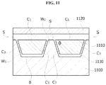
- FIG. 11 is a cross-sectional view of a soft magnetic layer and a receiving coil according to an embodiment of the present invention.
- receiving coils 1110 are formed on a soft magnetic layer 1100 , and a support means 1120 is formed on the receiving coils 1110 .
- the support means 1120 is for supporting the receiving coils 1110 , may include a PET material, and may have the form of a film.
- the soft magnetic layer 1100 , the receiving coils 1110 , and the support film 1120 may be adhered by an adhesive 1130 .
- the receiving coils 1110 may be wound in a spiral or helical shape in parallel with a plane of the soft magnetic layer 1100 .
- the receiving coils 1110 may have a round shape, a racetrack shape, a rectangular shape, a triangular shape, a polygonal shape with round corners and the like, but embodiments are not limited thereto.
- the receiving coils 1110 are embedded in one surface of the soft magnetic layer 1100 .
- at least one surface of the receiving coils 1110 may be obliquely embedded in the surface of the soft magnetic layer 1100 . That is, a wall surface of the receiving coils 1110 may be embedded in the surface of the soft magnetic layer 1100 to be inclined with respect to the surface instead of being perpendicular or parallel thereto.
- a cross-section of the receiving coils 1110 includes one side C 1 adjacent to a surface S of the soft magnetic layer 1100 , and at least one of two sides C 2 and C 3 which meet the side C 1 forms an inclination with the side C 1 .
- the at least one of the two sides C 2 and C 3 which meet the side C 1 may form an angle ⁇ which is 50° or larger and smaller than 90°, preferably, an angle ⁇ which is 60° or larger and 75° or smaller, and more preferably, an angle ⁇ which is 65° or larger and 70° or smaller, with the side C 1 .
- the side C 1 of the cross-section of the receiving coils 1110 may be a side belonging to a surface coming into contact with the support layer 1120 with the adhesive layer 1130 interposed therebetween.
- the side C 1 of the cross-section of the receiving coils 1110 may be a side belonging to a surface placed on the same plane as the surface S of the soft magnetic layer 1100 after the receiving coils 1110 are embedded.
- the receiving coils 1110 are formed so that the side C 1 adjacent to the surface S of the soft magnetic layer 1100 and at least one of the two sides C 2 and C 3 which meet the side C 1 form the angle ⁇ which is smaller than 90°, gaps between the receiving coils 1110 are widened, and the soft magnetic layer 1100 having fluidity may be easily infiltrated into the gaps. Accordingly, a large amount of soft magnetic material is filled into the gaps between the receiving coils 1110 such that voids between the receiving coils 1110 are removed after the receiving coils 1110 are embedded, the electromagnetic characteristic is improved, and the transmission efficiency is increased.
- the amount of soft magnetic material embedded between the receiving coils 1110 is increased as the side C 1 adjacent to the surface S of the soft magnetic layer 1100 and the at least one of the two sides C 2 and C 3 which meet the side C 1 is further smaller than 90°, a problem in which the thickness of the soft magnetic layer 1100 is increased due to the receiving coils 1110 being embedded therein can be mitigated. Accordingly, the total thickness of the soft magnetic layer 1100 and the receiving coils 1110 can be reduced.
- the side C 1 adjacent to the surface S of the soft magnetic layer 1100 and the at least one of the two sides C 2 and C 3 which meet the side C 1 is smaller than 50°, even though the thickness of the soft magnetic layer 1100 and the receiving coils 1110 can be further reduced, the amount of receiving coils 1110 is reduced, and the transmission efficiency is decreased.
- the adhesive layer 1130 may have a both-sided structure including an insulating layer.
- the adhesive layer 1130 may include a first adhesive layer, an insulating layer formed on the first adhesive layer, and a second adhesive layer formed on the insulating layer.
- the insulating layer may include a PET material. Accordingly, even when the first adhesive layer or the second adhesive layer are destroyed in a process for forming or embedding the receiving coils 1110 inside the soft magnetic layer 1100 , an electrical short circuit between metal and the receiving coils within the soft magnetic layer 1100 may be prevented.
- the cross-section of the receiving coils 1110 is illustrated as a trapezoid further including another side C 4 which is in parallel with the side C 1 adjacent to the surface S of the soft magnetic layer 1100 and meets the two sides C 2 and C 3 , embodiments are not limited thereto.
- a cross-section of receiving coils 1210 may be a polygon including one side C 1 adjacent to a surface S of a soft magnetic layer 1200 and two sides C 2 and C 3 which meet the side C 1 , and in which the side C 1 and at least one of the two sides C 2 and C 3 form an inclination which is 50° or larger and smaller than 90°.
- a cross-section of receiving coils 1310 may include one side C 1 adjacent to a surface S of a soft magnetic layer 1300 and two sides C 2 and C 3 which meet the side C 1 , the side C 1 and at least one of the two sides C 2 and C 3 may form an inclination which is 50° or larger and smaller than 90°, and the cross-section may further include a curve C 4 connecting the two sides C 2 and C 3 .
- a groove may be formed at one surface of a soft magnetic layer to accommodate a receiving coil therein.
- the groove may include both wall surfaces W 1 and W 2 which meet the surface S of the soft magnetic layer and a bottom surface B which meets the both wall surfaces W 1 and W 2 , and the surface S and at least one of the both wall surfaces W 1 and W 2 may form an inclination.
- the surface S and at least one of the both wall surfaces W 1 and W 2 may form an angle which is larger than 90° and is 130° or smaller.
- the receiving coils when the receiving coils are arranged on an upper surface of the soft magnetic layer, and then the soft magnetic layer and the receiving coils are compressed, the receiving coils may be embedded in the soft magnetic layer.
- the soft magnetic layer may have fluidity.
- the soft magnetic layer may be formed of a plurality of sheets containing soft magnetic metal powder and polymer resin.
- FIG. 14 is a flowchart illustrating a method of embedding a receiving coil in a soft magnetic layer according to an embodiment of the present invention.
- the soft magnetic layer is assumed as being formed of sheets containing soft magnetic metal powder and high polymer resin.
- sheets containing soft magnetic metal powder and polymer resin are manufactured (S 1400 ).
- ink containing a solvent, soft magnetic metal powder, and polymer resin may be casted onto a film to form a thin sheet.
- the soft magnetic metal powder may include, for example, an Fe—Si based alloy.
- the polymer resin may include, for example, at least one polymer resin of rubber-based polymer resin, epoxy-based polymer resin, and Si-based polymer resin.
- the plurality of sheets are disposed (S 1410 ), an adhesive layer is formed at an upper surface of the plurality of sheets (S 1420 ), receiving coils are arranged on the adhesive layer (S 1430 ), and the plurality of sheets, the adhesive layer, and the receiving coils are simultaneously compressed at high temperature (S 1440 ).
- the receiving coils may have inclined side surfaces.
- the cross-section of the receiving coils may have an inclination which is 50° or larger and smaller than 90° with the upper surface of the plurality of sheets.
- the compression process may be performed under pressure of 100 to 300 kgf/cm 2 for 0.5 to 4 hours at 80 to 250° C. For example, a start temperature 40° C.
- an initial pressure 10 kgf/cm 2 may be maintained for 15 minutes, the pressure may be raised up to 120 kgf/cm 2 in 15 minutes, and 120 kgf/cm 2 may be further maintained for an hour.
- the groove portion formed at the boundary surface between the sheets and the receiving coils is thermally hardened in the process of compressing at high temperature, the groove portion can be stably implemented.
- the polymer resin contained in the sheets becomes an insulating material with high thermal resistance by being compressed at high temperature, the polymer resin may perform an insulating function required between soft magnetic metal powder particles and prevent corrosion of the soft magnetic metal powder even in harsh outside environment.
- an electrical short circuit can be prevented during the high-pressure compression of the plurality of sheets and the receiving coils even when the adhesive layer is partially stripped.
- transmission efficiency (Tx-A1) was measured under conditions in which transmitting power was 3.5 W, 4.0 W, 4.5 W, and 4.9 W.
- Table 1 is a result of measuring final thicknesses and transmission efficiencies after compression in Embodiments 1 to 3 and Comparative examples 1 to 3
- FIG. 15 is a result showing final thicknesses after compression in Embodiments 1 to 3 and Comparative examples 1 to 3 with a graph
- FIG. 16 is a result showing transmission efficiencies in Embodiments 1 to 3 and Comparative examples 1 to 3 with a graph.
- Embodiments 1 and 2 in which wall surface of receiving coils is embedded in an angle of 70° or 65° the thickness is small and the transmission efficiency is high compared to Comparative example 1 in which receiving coils are not embedded and Comparative example 2 in which receiving coils are embedded in an angle of 90°.
- Embodiment 3 in which a wall surface of receiving coils is embedded in an angle of 50°, the transmission efficiency is similar but the thickness is significantly smaller compared to Comparative example 1 or Comparative example 2.
- an embodiment of the present invention is applied to a receiving antenna of a wireless power receiving apparatus for convenience of description, embodiments are not limited thereto.
- An embodiment of the present invention may also be applied to a structure between a soft magnetic core and a transmitting coil included in a transmitting antenna of a wireless power transmitting apparatus.
Landscapes
- Engineering & Computer Science (AREA)
- Power Engineering (AREA)
- Computer Networks & Wireless Communication (AREA)
- Physics & Mathematics (AREA)
- Electromagnetism (AREA)
- Chemical & Material Sciences (AREA)
- Dispersion Chemistry (AREA)
- Signal Processing (AREA)
- Charge And Discharge Circuits For Batteries Or The Like (AREA)
Abstract
Description
Q=w*Ls/Rs [Equation 1]
| TABLE 1 | |||
| Thickness | Transmission efficiency (Tx-A1) | ||
| No. | (μm) | 3.5 W | 4.0 W | 4.5 W | 4.9 |
| Embodiment |
| 1 | 629 | 71.43% | 71.03% | 70.07% | 68.82 |
| Embodiment | |||||
| 2 | 624 | 71.74% | 71.31% | 70.32% | 68.74 |
| Embodiment | |||||
| 3 | 613 | 70.24% | 69.60% | 68.69% | 67.25% |
| Comparative | 679 | 70.42% | 69.71% | 68.75% | 67.34% |
| example 1 | |||||
| Comparative | 647 | 70.97% | 70.17% | 69.36% | 67.69% |
| example 2 | |||||
| Comparative | 609 | 68.45% | 67.83% | 66.91% | 65.99% |
| example 3 | |||||
Claims (21)
Applications Claiming Priority (3)
| Application Number | Priority Date | Filing Date | Title |
|---|---|---|---|
| KR10-2014-0130527 | 2014-09-29 | ||
| KR1020140130527A KR102148847B1 (en) | 2014-09-29 | 2014-09-29 | Receiving antennas and wireless power receiving apparatus comprising the same |
| PCT/KR2015/009696 WO2016052887A1 (en) | 2014-09-29 | 2015-09-16 | Receiving antenna and wireless power receiving apparatus comprising same |
Publications (2)
| Publication Number | Publication Date |
|---|---|
| US20170213644A1 US20170213644A1 (en) | 2017-07-27 |
| US10636564B2 true US10636564B2 (en) | 2020-04-28 |
Family
ID=55630867
Family Applications (1)
| Application Number | Title | Priority Date | Filing Date |
|---|---|---|---|
| US15/515,431 Active 2036-07-19 US10636564B2 (en) | 2014-09-29 | 2015-09-16 | Receiving antenna and wireless power receiving apparatus comprising same |
Country Status (4)
| Country | Link |
|---|---|
| US (1) | US10636564B2 (en) |
| KR (1) | KR102148847B1 (en) |
| CN (1) | CN107078551B (en) |
| WO (1) | WO2016052887A1 (en) |
Families Citing this family (11)
| Publication number | Priority date | Publication date | Assignee | Title |
|---|---|---|---|---|
| US9553476B2 (en) * | 2012-03-23 | 2017-01-24 | Lg Innotek Co., Ltd. | Antenna assembly and method for manufacturing same |
| US9806565B2 (en) | 2012-03-23 | 2017-10-31 | Lg Innotek Co., Ltd. | Wireless power receiver and method of manufacturing the same |
| US10354794B2 (en) * | 2016-08-25 | 2019-07-16 | Witricity Corporation | Multi-coil base pad with angled structure |
| WO2018066894A1 (en) * | 2016-10-07 | 2018-04-12 | 주식회사 아모센스 | Wireless power transmitting antenna core and wireless power transmitting module including same |
| CN109818426B (en) * | 2017-11-20 | 2022-08-16 | 鹏鼎控股(深圳)股份有限公司 | Wireless charging device and manufacturing method thereof |
| JP7106943B2 (en) * | 2018-03-30 | 2022-07-27 | Tdk株式会社 | Coil unit, wireless power transmission device, wireless power reception device, wireless power transmission system |
| KR102022431B1 (en) | 2018-05-29 | 2019-11-25 | 엘지이노텍 주식회사 | Magnetic sheet and wireless power module including the same |
| US11380480B2 (en) | 2019-07-10 | 2022-07-05 | Lear Corporation | Strip induction coil for wireless charging of a vehicle battery |
| US11007887B2 (en) | 2019-07-11 | 2021-05-18 | Lear Corporation | Tubular induction coil for wireless charging of a vehicle battery |
| JP7040687B1 (en) * | 2020-05-22 | 2022-03-23 | 住友電気工業株式会社 | Turning tools and turning equipment |
| KR102312981B1 (en) | 2020-10-22 | 2021-10-15 | 더가우스 주식회사 | Wireless power reception apparatus and a method of manufacturing the same |
Citations (9)
| Publication number | Priority date | Publication date | Assignee | Title |
|---|---|---|---|---|
| US20050072595A1 (en) * | 2003-10-01 | 2005-04-07 | Cho Se-Hoon | Method of manufacturing substrate for circuit board and smart label having the substrate |
| KR20090056457A (en) | 2007-11-30 | 2009-06-03 | 가톨릭대학교 산학협력단 | MEMS-based electromagnetic induction generator and its manufacturing method |
| KR20120086669A (en) | 2011-01-26 | 2012-08-03 | 파나소닉 주식회사 | Contact-less Charging Module and Reception-side and Transmission-side Contact-less Charging Devices Using the Same |
| KR20130008858A (en) | 2011-07-13 | 2013-01-23 | 삼성전자주식회사 | Method for image processing and image processing apparatus thereof |
| KR101394508B1 (en) | 2013-03-22 | 2014-05-13 | 엘지이노텍 주식회사 | Soft magnetism sheet, wireless power receiving apparatus and wireless charging method of the same |
| KR20140066415A (en) | 2012-11-23 | 2014-06-02 | 삼성전기주식회사 | Cordless charging apparatus and electronic device having the same |
| US20140167521A1 (en) * | 2012-12-13 | 2014-06-19 | Lg Innotek Co., Ltd. | Wireless power receiver and method of manufacturing the same |
| US20150054455A1 (en) | 2012-01-09 | 2015-02-26 | Kthepower Inc. | Receiver for wireless charging system |
| US20150077296A1 (en) * | 2012-03-23 | 2015-03-19 | Lg Innotek Co., Ltd. | Antenna assembly and method for manufacturing same |
Family Cites Families (1)
| Publication number | Priority date | Publication date | Assignee | Title |
|---|---|---|---|---|
| KR20140089192A (en) * | 2013-01-04 | 2014-07-14 | 엘지이노텍 주식회사 | Soft magnetic sheet, soft magnetic plate and soft magnetic pellet for antenna of wireless power receiving apparatus |
-
2014
- 2014-09-29 KR KR1020140130527A patent/KR102148847B1/en not_active Expired - Fee Related
-
2015
- 2015-09-16 US US15/515,431 patent/US10636564B2/en active Active
- 2015-09-16 CN CN201580052817.6A patent/CN107078551B/en not_active Expired - Fee Related
- 2015-09-16 WO PCT/KR2015/009696 patent/WO2016052887A1/en not_active Ceased
Patent Citations (10)
| Publication number | Priority date | Publication date | Assignee | Title |
|---|---|---|---|---|
| US20050072595A1 (en) * | 2003-10-01 | 2005-04-07 | Cho Se-Hoon | Method of manufacturing substrate for circuit board and smart label having the substrate |
| KR20090056457A (en) | 2007-11-30 | 2009-06-03 | 가톨릭대학교 산학협력단 | MEMS-based electromagnetic induction generator and its manufacturing method |
| KR20120086669A (en) | 2011-01-26 | 2012-08-03 | 파나소닉 주식회사 | Contact-less Charging Module and Reception-side and Transmission-side Contact-less Charging Devices Using the Same |
| KR20130008858A (en) | 2011-07-13 | 2013-01-23 | 삼성전자주식회사 | Method for image processing and image processing apparatus thereof |
| US20150054455A1 (en) | 2012-01-09 | 2015-02-26 | Kthepower Inc. | Receiver for wireless charging system |
| US20150077296A1 (en) * | 2012-03-23 | 2015-03-19 | Lg Innotek Co., Ltd. | Antenna assembly and method for manufacturing same |
| KR20140066415A (en) | 2012-11-23 | 2014-06-02 | 삼성전기주식회사 | Cordless charging apparatus and electronic device having the same |
| US20140167521A1 (en) * | 2012-12-13 | 2014-06-19 | Lg Innotek Co., Ltd. | Wireless power receiver and method of manufacturing the same |
| KR20140076994A (en) | 2012-12-13 | 2014-06-23 | 엘지이노텍 주식회사 | Wireless power receiver and method of manufacturing the same |
| KR101394508B1 (en) | 2013-03-22 | 2014-05-13 | 엘지이노텍 주식회사 | Soft magnetism sheet, wireless power receiving apparatus and wireless charging method of the same |
Non-Patent Citations (2)
| Title |
|---|
| International Search Report in International Application No. PCT/KR2015/009696, filed Sep. 16, 2015. |
| Office Action dated Feb. 27, 2020 in Korean Application No. 10-2014-0130527. |
Also Published As
| Publication number | Publication date |
|---|---|
| US20170213644A1 (en) | 2017-07-27 |
| WO2016052887A1 (en) | 2016-04-07 |
| KR102148847B1 (en) | 2020-08-27 |
| CN107078551A (en) | 2017-08-18 |
| KR20160037650A (en) | 2016-04-06 |
| CN107078551B (en) | 2020-07-24 |
Similar Documents
| Publication | Publication Date | Title |
|---|---|---|
| US10636564B2 (en) | Receiving antenna and wireless power receiving apparatus comprising same | |
| US10468918B2 (en) | Receiving antenna and wireless power receiving device including the same | |
| US10333358B2 (en) | Receiving antenna and wireless power receiving device including the same | |
| US9460847B2 (en) | Soft magnetic layer, receiving antenna, and wireless power receiving apparatus comprising the same | |
| US11569577B2 (en) | Antenna module comprising shield layer and wireless power receiving device | |
| US20190214180A1 (en) | Magnetic sheet and wireless power receiving device comprising same | |
| KR102742227B1 (en) | Magnetic sheet and wireless power receiving apparatus including the same | |
| US10075009B2 (en) | Receiving antenna and wireless power receiving device including the same | |
| US20170222472A1 (en) | Wireless power transmitting apparatus and wireless power receiving apparatus | |
| KR102348411B1 (en) | Shielding unit for complex-antenna unit and complex-transmission module comprising the same | |
| US20210249166A1 (en) | Magnetic sheet and wireless power module comprising same | |
| KR102348413B1 (en) | Shielding unit for complex-antenna unit and complex-transmission module comprising the same | |
| KR102348412B1 (en) | Shielding unit for complex-antenna unit and complex-transmission module comprising the same | |
| KR102323182B1 (en) | Shielding unit for complex-antenna unit and complex-transmission module comprising the same | |
| KR102310769B1 (en) | Shielding unit for complex-antenna unit and complex-transmission module comprising the same | |
| KR102081319B1 (en) | Receiving antennas and wireless power receiving apparatus comprising the same | |
| KR102310770B1 (en) | Shielding unit for complex-antenna unit and complex-transmission module comprising the same |
Legal Events
| Date | Code | Title | Description |
|---|---|---|---|
| STPP | Information on status: patent application and granting procedure in general |
Free format text: DOCKETED NEW CASE - READY FOR EXAMINATION |
|
| AS | Assignment |
Owner name: LG INNOTEK CO., LTD., KOREA, REPUBLIC OF Free format text: ASSIGNMENT OF ASSIGNORS INTEREST;ASSIGNORS:LEE, JUNG EUN;LEE, SANG WON;BAE, SEOK;AND OTHERS;SIGNING DATES FROM 20170322 TO 20170323;REEL/FRAME:043298/0775 |
|
| STPP | Information on status: patent application and granting procedure in general |
Free format text: NON FINAL ACTION MAILED |
|
| STPP | Information on status: patent application and granting procedure in general |
Free format text: RESPONSE TO NON-FINAL OFFICE ACTION ENTERED AND FORWARDED TO EXAMINER |
|
| STPP | Information on status: patent application and granting procedure in general |
Free format text: FINAL REJECTION MAILED |
|
| STPP | Information on status: patent application and granting procedure in general |
Free format text: NOTICE OF ALLOWANCE MAILED -- APPLICATION RECEIVED IN OFFICE OF PUBLICATIONS |
|
| STCF | Information on status: patent grant |
Free format text: PATENTED CASE |
|
| AS | Assignment |
Owner name: SCRAMOGE TECHNOLOGY LIMITED, IRELAND Free format text: ASSIGNMENT OF ASSIGNORS INTEREST;ASSIGNOR:LG INNOTEK CO., LTD.;REEL/FRAME:055335/0652 Effective date: 20210202 Owner name: SCRAMOGE TECHNOLOGY LIMITED, IRELAND Free format text: ASSIGNMENT OF ASSIGNOR'S INTEREST;ASSIGNOR:LG INNOTEK CO., LTD.;REEL/FRAME:055335/0652 Effective date: 20210202 |
|
| MAFP | Maintenance fee payment |
Free format text: PAYMENT OF MAINTENANCE FEE, 4TH YEAR, LARGE ENTITY (ORIGINAL EVENT CODE: M1551); ENTITY STATUS OF PATENT OWNER: LARGE ENTITY Year of fee payment: 4 |
|
| AS | Assignment |
Owner name: NERA INNOVATIONS LIMITED, IRELAND Free format text: ASSIGNMENT OF ASSIGNORS INTEREST;ASSIGNOR:SCRAMOGE TECHNOLOGY LIMITED;REEL/FRAME:066778/0214 Effective date: 20240305 Owner name: NERA INNOVATIONS LIMITED, IRELAND Free format text: ASSIGNMENT OF ASSIGNOR'S INTEREST;ASSIGNOR:SCRAMOGE TECHNOLOGY LIMITED;REEL/FRAME:066778/0214 Effective date: 20240305 |