US10634747B2 - Apparatus and implementation method of a set of universal compact portable MR-compatible PET inserts to convert whole-body MRI scanners into organ-specific hybrid PET/MRI imagers - Google Patents
Apparatus and implementation method of a set of universal compact portable MR-compatible PET inserts to convert whole-body MRI scanners into organ-specific hybrid PET/MRI imagers Download PDFInfo
- Publication number
- US10634747B2 US10634747B2 US13/827,557 US201313827557A US10634747B2 US 10634747 B2 US10634747 B2 US 10634747B2 US 201313827557 A US201313827557 A US 201313827557A US 10634747 B2 US10634747 B2 US 10634747B2
- Authority
- US
- United States
- Prior art keywords
- pet
- mri
- patient
- photodetector
- coil
- Prior art date
- Legal status (The legal status is an assumption and is not a legal conclusion. Google has not performed a legal analysis and makes no representation as to the accuracy of the status listed.)
- Expired - Fee Related, expires
Links
Images


Classifications
-
- G—PHYSICS
- G01—MEASURING; TESTING
- G01R—MEASURING ELECTRIC VARIABLES; MEASURING MAGNETIC VARIABLES
- G01R33/00—Arrangements or instruments for measuring magnetic variables
- G01R33/20—Arrangements or instruments for measuring magnetic variables involving magnetic resonance
- G01R33/44—Arrangements or instruments for measuring magnetic variables involving magnetic resonance using nuclear magnetic resonance [NMR]
- G01R33/48—NMR imaging systems
- G01R33/4808—Multimodal MR, e.g. MR combined with positron emission tomography [PET], MR combined with ultrasound or MR combined with computed tomography [CT]
- G01R33/481—MR combined with positron emission tomography [PET] or single photon emission computed tomography [SPECT]
-
- A—HUMAN NECESSITIES
- A61—MEDICAL OR VETERINARY SCIENCE; HYGIENE
- A61B—DIAGNOSIS; SURGERY; IDENTIFICATION
- A61B6/00—Apparatus or devices for radiation diagnosis; Apparatus or devices for radiation diagnosis combined with radiation therapy equipment
- A61B6/02—Arrangements for diagnosis sequentially in different planes; Stereoscopic radiation diagnosis
- A61B6/03—Computed tomography [CT]
- A61B6/037—Emission tomography
-
- A—HUMAN NECESSITIES
- A61—MEDICAL OR VETERINARY SCIENCE; HYGIENE
- A61B—DIAGNOSIS; SURGERY; IDENTIFICATION
- A61B6/00—Apparatus or devices for radiation diagnosis; Apparatus or devices for radiation diagnosis combined with radiation therapy equipment
- A61B6/44—Constructional features of apparatus for radiation diagnosis
- A61B6/4417—Constructional features of apparatus for radiation diagnosis related to combined acquisition of different diagnostic modalities
-
- A—HUMAN NECESSITIES
- A61—MEDICAL OR VETERINARY SCIENCE; HYGIENE
- A61B—DIAGNOSIS; SURGERY; IDENTIFICATION
- A61B6/00—Apparatus or devices for radiation diagnosis; Apparatus or devices for radiation diagnosis combined with radiation therapy equipment
- A61B6/50—Apparatus or devices for radiation diagnosis; Apparatus or devices for radiation diagnosis combined with radiation therapy equipment specially adapted for specific body parts; specially adapted for specific clinical applications
- A61B6/501—Apparatus or devices for radiation diagnosis; Apparatus or devices for radiation diagnosis combined with radiation therapy equipment specially adapted for specific body parts; specially adapted for specific clinical applications for diagnosis of the head, e.g. neuroimaging or craniography
-
- G—PHYSICS
- G01—MEASURING; TESTING
- G01T—MEASUREMENT OF NUCLEAR OR X-RADIATION
- G01T1/00—Measuring X-radiation, gamma radiation, corpuscular radiation, or cosmic radiation
- G01T1/16—Measuring radiation intensity
- G01T1/1603—Measuring radiation intensity with a combination of at least two different types of detectors
-
- G—PHYSICS
- G01—MEASURING; TESTING
- G01T—MEASUREMENT OF NUCLEAR OR X-RADIATION
- G01T1/00—Measuring X-radiation, gamma radiation, corpuscular radiation, or cosmic radiation
- G01T1/29—Measurement performed on radiation beams, e.g. position or section of the beam; Measurement of spatial distribution of radiation
- G01T1/2914—Measurement of spatial distribution of radiation
- G01T1/2985—In depth localisation, e.g. using positron emitters; Tomographic imaging (longitudinal and transverse section imaging; apparatus for radiation diagnosis sequentially in different planes, steroscopic radiation diagnosis)
Definitions
- the present disclosure is generally directed toward a combination of Position Emission Tomography (“PET”) and Magnetic Resonance Imaging (“MRI”) system technologies and, more particularly, toward hybrid PET-MRI imaging systems and methods and, even more particularly, towards systems and methods of providing MR-compatible PET inserts for converting whole-body MRI scanners into organ-specific PET/MRI imagers.
- PET Position Emission Tomography
- MRI Magnetic Resonance Imaging
- PET/MRI scanners are just entering the market; however, these scanners are complicated and very expensive (approximately $6-million), making it prohibitive for medical centers to acquire them. Accordingly, they will have limited availability to most patients for many years to come. It is proposed herein to provide an alternative, low-cost system and method, mostly (but not only) applicable to imaging of a particular organ, such as, but not limited to, brain, breast, head/neck, prostate, OB/GYN, heart, and other extremities, by the inventive implementation of PET inserts in any MRI scanner.
- a particular organ such as, but not limited to, brain, breast, head/neck, prostate, OB/GYN, heart, and other extremities
- the present disclosure is directed toward overcoming one or more of the above-identified problems.
- PET and MRI imaging are powerful imaging techniques used, for example, in biomedical research and clinical diagnostics.
- PET imaging in combination with a radioactive tracer, provides molecular information about specific tissues and organs and enables the visualization of biological activity.
- CT Computed Tomography
- MRI scans Both CT and MRI scans provide detailed information about the internal structures of the body.
- PET scans are immediately followed by a CT or MRI scan, although more recently, a tandem PET/CT machine has been used in clinical imaging.
- PET/CT systems are useful, CT technology is not as sensitive as MRI data, especially in terms of soft tissue contrast data. Additionally, CT scans can expose the patient to higher radiation doses. Therefore, there is a clear need for a PET/MRI dual imaging system that can combine the advantages of both imaging systems.
- the inventors herein have created a portable PET imager that is very compact and made to be MRI-compatible, so that it can operate as an insert inside the MRI scanners.
- the inventors herein have thus creating a PET/MRI dual imaging system.
- the PET insert is in a form of a ring of individual detection modules that surround the patient's head. But the same ring can be used to image neck, breast, or other extremities.
- the PET insert is in the form of several planar—panel type—modules that operate in coincidence inside the MRI scanner.
- the system can be comprised of a compact endorectal or surgical PET probe operating in coincidence with the panel modules. Such an embodiment is particularly useful for imaging the prostate gland and surrounding organs in a patient.
- the approach of a single PET insert in MRI can be extended to a set of inserts to cover different parts of the body at the same time.
- the inserts can increase their coverage to larger regions of the patient's body, and can be offered as an upgrade option to operate with almost any MRI scanner.
- the PET insert requires availability and proper installation of MRI model specific Radio Frequency (“RF”) coils to minimize the interference of the PET insert (primarily, the impact is through the decreased signal to noise ratio of the MRI signal) on the MRI operation.
- RF Radio Frequency
- the standard, also flexible, RF coils provided with the MRI scanner will suffice. When operated with a whole body RF coil, some MRI imaging sequences may be impacted and cannot be used, while some may still provide sufficient quality images.
- a detailed evaluation of the compatibility of the PET insert(s) with the particular MRI scanner model needs to be performed.
- the optimal RF coil selection should be performed for each individual PET insert and MRI.
- special case-specific RF coils may need to be implemented with each PET insert for a particular MRI model and mode of operation (e.g., imaging sequences) so as to minimize or eliminate interference effect of the PET insert on the MRI scanner operation.
- Variations of the present invention can include more MRI-model specific PET inserts, as opposed to generic ones, operating, in principle, with any MRI scanner.
- the MRI RF coils can be built into, or incorporated as part of, the structure of the PET insert.
- the flexibility of the inventive solution may be diminished. Careful balancing of the operational parameters versus the complexity and flexibility of this “upgrade” of an MRI scanner to a dedicated organ-specific (e.g., brain, breast, neck, extremity, prostate, OB/GYN, heart, etc.) PET/MRI scanner needs to be performed on a case by case basis, working with MRI scanner producers and the medical center customers.
- organ-specific e.g., brain, breast, neck, extremity, prostate, OB/GYN, heart, etc.
- the present invention offers various improvements and differentiators with respect to prior art techniques. Some of which include:
- inventive technical approach described herein is the consequence of the current inventors' general philosophy (against the common approach) that proposes to use the PET inserts that can be brought to operate inside practically any MRI scanner with only minimal necessary adaptation of the MRI imaging procedure to be able to produce hybrid PET/MRI images.
- any existing whole-body MRI scanner (with about 36,000 currently installed in the world) can be, at low cost and practically with no or minimal modifications/adaptations, converted into an organ-specific PET/MRI imager.
- the first focus that has been considered is PET/MRI brain imaging.
- imaging of body parts and organs is also contemplated including, but not limited to, head/neck, breast, prostate, OB/GYN, heart, and other extremities, which are other envisaged applications.
- a PET insert for use with an MRI scanning device including a plurality of photodetector modules provided adjacent each other in an array, the plurality of photodetector modules configured for placement adjacent a body of a patient and sized to be received in a magnetic bore of the MRI scanning device with the patient, and the photodetector modules providing detection of gamma annihilation photons; and an RF coil provided between the patient and the plurality of photodetector modules.
- Each of the plurality of photodetector modules includes a pixelated scintillator array provided for alignment adjacent the patient's body, and a shielding block including silicon photomultiplier pads and passive electronic circuitry.
- the plurality of photodetector modules is formed as a ring for provision about a body part of the patient.
- the RF coil is provided about at least part of an annular range of the photodetector module ring.
- the ring can include a plurality of rings stacked on top of each other forming a cylinder.
- the ring can also include a plurality of rings, with at least some of the rings spaced apart from other rings for provision about different parts of a patient's body.
- each shielding block includes passive electronic circuitry only, such that the active components of the PET insert are disposed outside of the magnetic bore of the MRI scanner.
- the RF coil extends past the edges of the plurality of photodetectors.
- the RF coil can be a standard coil provided with the MRI scanner with which the PET insert is used, or can include a whole body RF coil.
- the plurality of photodetector modules is formed as a panel having an N ⁇ M array of photodetector modules.
- at least two PET panels are provided for provision against a patient's body in opposing relationship for imaging a desired portion of the patient's body.
- An endorectal PET probe operatively associated with the PET panel can be provided for imaging of, for example the prostate or vaginal regions.
- the photodetector modules include a scintillator as a sensor and energy converter of 511 keV annihilation gamma rays, and a photodetector to detect the scintillation light produced by the absorbed gamma rays in the scintillator.
- a PET insert for use with an MRI scanning device including a plurality of photodetector modules provided adjacent each other in an array and formed as a ring for provision around a portion of a patient's body, the photodetector module ring sized to be received in a magnetic bore of the MRI scanning device with the patient, the photodetector modules providing detection of gamma annihilation photons; and an RF coil provided between the patient and the plurality of photodetector modules.
- the RF coil is provided about at least part of an annular range of the photodetector module ring, and extends over the edges of the photodetector module ring.
- Each of the plurality of photodetector modules includes a pixelated scintillator array provided for alignment adjacent the patient's body, and a shielding block including silicon photomultiplier pads and passive electronic circuitry only.
- the photodetector module ring includes a plurality of rings stacked on top of each other forming a cylinder.
- the photodetector module ring includes a plurality of rings, at least some of the rings spaced apart from other rings for provision about different parts of a patient's body.
- a PET insert for use with an MRI scanning device including a plurality of photodetector modules provided adjacent each other in an array and formed as at least two panels for provision against a patient's body in opposing relationship for imaging a desired portion of the patient's body, the at least two photodetector module panels sized to be received in a magnetic bore of the MRI scanning device with the patient.
- the photodetector modules providing detection of gamma annihilation photons.
- An RF coil is provided between the patient and the plurality of photodetector modules of each of the at least two panels, wherein the RF coil extends over the edges of the at least two photodetector module panels.
- Each of the plurality of photodetector modules includes a pixelated scintillator array provided for alignment adjacent the patient's body, and a shielding block including silicon photomultiplier pads and passive electronic circuitry only.
- each of the at least two panels has an N ⁇ M array of photodetector modules.
- an endorectal PET probe is provided that is operatively associated with the at least two PET panels.
- Such a configuration has particularly utility for imaging the prostate and/or vaginal regions.
- FIG. 1 illustrates an exemplary MRI scanning room environment for use with the PET inserts of the present invention
- FIGS. 2A-C illustrate various views of the PET insert of the present invention provided within an MRI scanner
- FIGS. 3A-D illustrate conceptual views from above the patient's head of the PET inserts of the present invention configured as a brain imaging system including a ring of detector modules arranged around the patient's head ( FIG. 3A illustrates a prior art device);
- FIGS. 4A-B illustrate a prior art PET/MRI system
- FIG. 4C is a data flow diagram of the prior art PET/MRI system of FIGS. 4A-B ;
- FIG. 5 illustrates a 4 ⁇ 2 module panel in a two-ring PET insert
- FIG. 6 illustrates a 4 ⁇ 3 module panel in a three-ring PET insert
- FIGS. 7A-D illustrate exemplary single and multiple PET rings for imaging the head of a patient
- FIGS. 8A-C illustrate exemplary multi-ring, spaced apart PET imager for imaging the head and/or neck regions of a patient
- FIGS. 9A-D illustrate an exemplary embodiment of the present invention utilized for breast scanning with the patient in a prone position
- FIGS. 10A-B illustrate an exemplary embodiment of the present invention utilized for breast scanning with the patient in a supine position
- FIGS. 11A-E illustrate an exemplary embodiment of the present invention utilized for prostate imaging
- FIG. 12 illustrates an exemplary endorectal PET probe utilized for prostate screening
- FIGS. 13A-C illustrate conceptual diagrams of the exemplary endorectal PET probe sensor shown in FIG. 12 ;
- FIGS. 14A-B illustrate an exemplary embodiment of the present invention utilized for vaginal imaging
- FIGS. 15A-C illustrate an exemplary embodiment of the present invention utilized for cardiac imaging
- FIGS. 16A-C illustrate exemplary embodiments of the present invention utilized for extremity (arm and leg) imaging
- FIGS. 17A-C illustrate brain images taken from a brain phantom using an exemplary PET ring embodiment of the present invention
- FIG. 18 illustrates twelve reconstructed 1 mm slices of the brain phantom obtained with an exemplary PET ring embodiment of the present invention
- FIGS. 19A-C illustrate brain images demonstrating basic flood correction of the reconstructed images from an exemplary ring PET, in accordance with the present inventive
- FIGS. 20A-B illustrate two MRI images taken by an exemplary ring PET, including 2 mm slices of the brain phantom using the MPRAGE RF pulse sequence;
- FIGS. 21A-B illustrate two MRI images taken by an exemplary ring PET, including 2 mm slices of the brain phantom using the T2 sequence;
- FIGS. 22A-C show dual modality imaging performed in a 3 Tesla MRI scanner in accordance with an exemplary demonstration of the present invention.
- Nuclear medicine imaging modalities e.g., PET, single gamma, SPECT (Single-Photon Emission Computed Tomography)
- SPECT Single-Photon Emission Computed Tomography
- CT Computer Tomography
- the source of radiation is external to the patient and the X-ray beam is sent through the patient's body with a large fraction of radiation being absorbed and, therefore, delivering a radiation dose to the patient's organs and tissue.
- the possible methods that can lead to a decrease in the injected radioactive dose into the patient include, but are not limited to:
- the best approach will depend on the interplay between the dose, specificity (due to biology) of the imaging agent, and detector efficiency and spatial resolution, on the one side, and imaging quality (e.g., S/N, contrast, etc.) on the other side, for different size structures of interest/lesions to detect and diagnose.
- imaging quality e.g., S/N, contrast, etc.
- the specificity of the imaging agents is a critical component of the strategy on reduction the radioactive doses. Higher differentiation of uptake of imaging agent in diseased versus healthy organ or tissue can allow for lower doses while not compromising the above differentiation.
- the development of new imaging agents and the approval for their use in humans takes many years, while improvements in the detector technology could be implemented on a much shorter time scale.
- the special technical subject is the issue of spatial resolution of the novel dedicated nuclear medicine imagers.
- the very high resolution systems offering 1 mm and even sub-mm spatial resolution (typical of the small animal imagers); and, on the other end, the “pattern” imagers when the demand for spatial resolution is not a major driver.
- An example for the requirement for high resolution is the use of PET in breast imaging or prostate imaging.
- the detection of Alzheimer's is an example of the second “pattern” category, where 4 mm or even 8 mm resolution may be sufficient.
- the present disclosure is focused on task-specific performance, and the results of system optimization, including the radiation dose, will depend, at least in part, on the particular case.
- the present disclosure connects with the individual medicine approach, as the optimal parameters will be disease- and organ-, but will also include patient-specific.
- the separate special subject theme is the imaging of pediatric patients, e.g., infants and small children.
- the current radiation doses even when normalized to the child's body weight, are often deemed too risky and, therefore, a barrier against the even potentially life-saving diagnostic tests is raised.
- PET/MRI multimodal imaging is a major challenge to the imaging field.
- PET uses photomultiplier tubes for detection of scintillation light.
- both imaging techniques detract from the operation of the other.
- the magnetic field created by MRI scans impacts light yield of scintillator materials, thus causing interference in the PET imaging process.
- the PET detector causes disturbances to the magnetic field, leading to artifacts in the MR images.
- tandem PET/MRI an integrated molecular-genetic imaging system with HRRT-PET and 7.0-T MRI, Int'l J. Imaging Sys. Tech. 2007; 17:252-65).
- the PET insert system of the present invention where a removable PET scanner, designed to be MRI-compatible, is used within any MRI system.
- the inventors herein have created such a portable PET imager.
- the portable PET imager is in the form of a ring of individual detection modules (currently fitted tightly around the patient's head; although later could be fitted to other anatomical regions).
- the technology used by the inventors herein includes, for example, a Silicon Photomultiplier (“SiPM”) photo sensor.
- SiPM Silicon Photomultiplier
- the PET inserts require installation of MRI-model specific RF coils that would minimize the interference between the MRI and the PET insert.
- the inventors herein contemplate imaging performed with either the whole body RF coils built into the MRI scanner or standard flexible coils delivered with the scanner.
- the overall approach contemplated herein is to have the PET inserts operate within any MRI scanner, with only minimal changes.
- the key guiding new paradigm philosophy behind the inventive concept is that it is possible, by implementing relatively technically simple and robust and economical means, to convert practically any MRI scanner to an organ-specific PET/MRI imager (e.g., brain, head/neck, breast, prostate, colon, gynecological, pancreas, stomach, extremities, etc.).
- organ-specific PET/MRI imager e.g., brain, head/neck, breast, prostate, colon, gynecological, pancreas, stomach, extremities, etc.
- the strong motivator for this concept is that while the new hybrid PET/MRI imagers have important advantages over standard PET/CT systems, they are very expensive, often up to 3-4 times the PET/CT scanner cost. It is also postulated herein that no, or only minimal, additional adaptation means are necessary through implementation of properly designed organ-specific PET inserts in MRI scanners to obtain good quality PET/MRI images of the selected organ or body part.
- the universal, MR scanner-independent portable PET inserts will not require any special attachment procedures to operate with MRI scanners.
- the only requirement will be to validate that the quality of the MRI images (e.g., signal-to-noise, uniformity, etc.) will not be impacted by the PET inserts. Therefore, the present inventive concept is an enabling concept to propagate the implementation of a life-saving PET/MRI diagnostic technique by offering a “kit” of PET inserts that can be used with any MRI scanner. At present there are an estimated 36,000 MRI scanners in the world.
- the PET detector insert modules are placed very close to the patient body to make them more compact and mechanically compatible with operation inside the magnet bore of the MRI, and also to increase detection sensitivity.
- the detection modules form a tight ring allowing only for an insertion of the thin RF coil between the ring and the patient's head
- the universal portable PET inserts of the present invention which are placed inside the bore of an MRI scanner have no active electronics on-board, except the photodetectors (e.g., Silicon Photomultipliers or Avalanche Photodiodes).
- the active electronics in this case, are at a convenient distance outside the magnet bore, typically 1-10 feet counting from the edge of the bore.
- the PET insert component is placed outside the inner standard solid or flexible RF coil, while both the insert and the RF coil are placed inside the bore of the MRI scanner.
- the PET insert has no active electronics on-board, except the photodetectors (e.g., Silicon Photomultipliers or Avalanche Photodiodes).
- the photodetectors e.g., Silicon Photomultipliers or Avalanche Photodiodes.
- some of the active electronics can be still in the magnet bore, although they should be at a convenient distance from the end of the RF coil, typically 1-20 inches.
- specialized PET inserts on-board passive readout electronics is analog position-encoding. This substantially reduces the number of readout analog signals that need to be sent to the electronic circuitry placed outside the magnet bore, and then sent to the digitizing circuitry. Additionally, this substantially reduces the complexity and cost of the PET inserts themselves.
- the only RF coils used during the combined MRI and PET imaging sessions are: (1) the standard whole body coil; or (2) the manufacturer provided standard solid or flexible attachment coil(s). This reduces the cost and complexity of the PET inserts.
- the calibration and the uniformity correction of the tomographic reconstruction response of the inventive imager are typically performed by simulations, but also can be done experimentally by implementing uniform phantoms.
- a cylindrical uniform phantom is placed inside the ring and the high statistics reconstructed images are used as the base of the system response.
- geometrical response non-uniformities which are ever present in any system, are recorded and appropriate correction measures can be undertaken.
- the reconstructed object or patient images can be divided by corresponding uniform phantom images.
- This very simple technique offers immediate “on-the-go” uniformity, and also absorption correction.
- more sophisticated correction techniques can also be used involving, for example, a mixture of simulation and experimental data.
- FIGS. 1-2 illustrate one implementation form of the PET insert of the present invention configured as a brain ring.
- FIG. 1 illustrates an MRI scanning room, shown generally at 10 .
- the room 10 includes an MRI scanning device 12 .
- a PET insert 14 in the form of a brain ring, is provided which is designed to fit around the head of a patient and be received within the magnetic bore of the MRI scanner 12 while being worn by the patient.
- the PET insert 14 also includes an RF coil 16 , shown more clearly in FIGS. 2-3 . Only the basic necessary front-end PET ring electronics 18 (shown in FIG.
- a screened cable bunch 22 connects the electronics 18 inside the MRI room 10 with the rack/cabinet electronics 20 outside the MRI room 10 , exiting the MRI room 10 via a provided standard wall port 24 .
- the RF coil 16 is placed inside the ring of PET inserts 14 and preferentially extends past the edge of the PET insert 14 (as shown in FIG. 2C ).
- FIGS. 3A-D illustrate conceptual views from above the patient's head of the PET inserts of the present invention configured as a brain imaging system including a ring of detector modules arranged around the patient's head ( FIG. 3A illustrates a prior art device).
- FIG. 3A illustrates a prior art brain imaging system 30 , which includes a set of photodetector modules 32 formed as a ring for fitting around the head of a patient.
- the photodetector modules 32 each include respective scintillator blocks 34 and shielding boxes 36 .
- an RF coil 38 is integrally built into the PET ring 30 .
- the shielding boxes 32 each includes SiPM photo sensors and active electronic circuitry. This enables the ring 30 to operate as a stand-alone brain scanner.
- FIGS. 3B-D illustrate the novel PET inserts 50 (i.e., detector modules) formed as a ring 52 designed to fit around a patients head.
- Each of the detector modules 50 includes respective scintillator blocks 54 and shielding boxes 56 .
- the shielding boxes 56 include no active circuitry (they include passive electronic circuitry only), except for SiPM light sensors.
- an RF coil 58 placed between the object to image (e.g., patient's head 60 ) and the ring detector modules 50 .
- the RF coil 58 is placed close to the inner ring surface. Additionally, the coil 58 does not have to cover the full angular range, but can offer only partial coverage.
- FIG. 3B shows a coil 58 extending around the entire angular displacement
- FIG. 3C shows the coil 58 extending only partially around the angular displacement
- FIG. 3D shows a coil 58 having a two-piece, front-back configuration.
- a preferred coil type is one of the flexible standard coils from the package of coil attachments to the particular MRI scanner model. Such coils are typically provided with the MRI scanner module.
- FIGS. 3B-D show twelve detector modules 50 forming the ring 52 , any number of detector modules 50 may be used without departing from the spirit and scope of the present invention.
- FIGS. 4A-C depict a prior art system incorporating a brain PET/MRI insert concept. Such a system is described particularly at:
- a specially built RF coil 80 must accompany the PET ring, and include a PET gantry 82 , a PET gantry holder 84 and an RF coil holder 86 .
- These items add to the complexity, cost and size of the device.
- the prior art design has to have an additional stand-off distance between the PET ring and the object (head in this case) and larger ring diameter to accommodate the applied RF coil(s) 80 .
- the prior art system loses flexibility and portability.
- the complexity and cost also increases.
- the detection sensitivity of the ring is lower for larger diameters of the ring, resulting in a degradation of performance.
- the inventive concept disclosed herein includes a PET ring design that very closely follows the patient's head. Additionally, the present invention does not use a specially built RF coil accompanying the PET ring, nor the standard brain coil. In contrast, the present invention, in a preferred embodiment, uses a standard flexible RF coil provided with the MRI scanner, allowing for much tighter structure of the PET ring. While both the present invention and the prior art device shown in FIG. 4 place the electronics box outside the magnet bore of the MRI scanner, the present invention utilizes an on-board analog readout that is position-encoded with highly reduced number of exiting analog signal channels. Such position encoding is not found in prior art devices. For example, as shown in FIG.
- analog signals from all SiPM channels have to be sent to the pre-amplifying electronics, shown at 88 , and then only after compression in a position decoder 90 , are the analog signals sent to digitizing electronics. This results in a more complicated, bulky and expensive readout system.
- each of the SiPM modules (built out of an array of N ⁇ M individual SiPM pixels) has a passive (e.g., made out of resistors, capacitors, diodes) charge division circuit that reduces the number of analog channels from N ⁇ M to four.
- a passive e.g., made out of resistors, capacitors, diodes
- only these four channels per module are exiting the PET insert in the MRI magnet bore and connect via the cable to the processing circuitry
- the analog outputs from the N ⁇ M array of SiPM pixels are reduced in the passive charge division circuit to N+M sector analog outputs.
- These N+M module outputs can be further connected, or chained, to form panel/sector “super-modules” in order to reduce the number of sector readout channels.
- FIGS. 5-6 illustrate the general concept of how to implement the high performing channel-reducing on-board (the PET insert) passive circuitry (using only resistors, diodes and capacitors), where the row and column outputs from individual detector modules, that are arranged in rings or panels, are passively chained to form X and Y readout sectors.
- FIG. 5 shows a 4 ⁇ 2 module panel in a two-ring PET insert
- FIG. 6 shows a 4 ⁇ 3 module panel in a three-ring PET insert.
- Such an 8-module group could be a 4 ⁇ 2 module panel (as shown in FIG. 5 ), but also a sector in a two-ring PET insert, etc.
- This needs to be compared with a direct readout of all SiPM pixels in this panel, which is equal to 144 ⁇ 8 1152.
- a channel reduction factor of 16 is thus achieved in this example.
- a similar channel reduction following a similar approach can also be achieved for the 4 ⁇ 3 module panel shown in FIG. 6 .
- prior art approaches require signals from all SiPM pixels to be first exited from the magnet bore and amplified, before they would be processed in any channel reducing circuitry, resulting in increased complexity, cost and space requirements.
- FIG. 7A illustrates an example of a schematic of a single imager PET ring, shown herein with twelve individual MRI-compatible PET modules 14 , which are divided into two parts, for easy placement and adjustment on, for example, the patient's head/brain/neck.
- Each of the individual modules 14 is made from a matrix of pixelated LYSO crystals coupled to an array of solid-state Silicon Photo-Multipliers (SiPM).
- FIGS. 7B-C illustrate an example of an elongated PET ring built with fourteen individual modules 14 , which is better adapted to the shape of the human head.
- any number of individual modules 14 may be incorporate into a given design without departing from the spirit and scope of the present invention.
- only a single ring of modules 14 is built.
- multi-ring systems such as, for example, the three-ring system shown in FIG. 7D , that will cover the whole brain in one position can be built.
- FIG. 8A illustrates such a two-ring variant with two rings spaced apart with an adjustable spacing.
- FIG. 8B illustrates such an “open PET” type arrangement provides a larger field of view at a reduced complexity and cost.
- one of the rings 100 can be place above the ears at the brain level, while another ring 102 can be placed at the neck level, for example, during first path dynamic blood flow imaging with the neck ring measuring the so called input function in the carotid artery, as shown in FIG. 8C .
- FIGS. 9A-D illustrate an embodiment of the present invention utilized for breast scanning with the patient in a prone position.
- FIG. 9A illustrates the PET modules 14 formed as a ring for receiving a breast 110 of a patient.
- the RF coil 16 is provided between the modules 14 and the patient's breast 110 .
- the RF MRI coils are provided between the breast 110 and each of the rings of PET modules 14 .
- the PET breast inserts can also have single ( FIG. 9A ), two ( FIGS. 9C-D ) or three ( FIG. 9B ) or more rings. In a multi-ring variant, the top ring will typically be placed adjacent the chest wall.
- the imager's active edge extends to the chest wall so that the PET coincidence lines of response (“LORs”) at the upper edge of the imager (shown as dashed line 112 ) include the tissue at the base of the breast 110 .
- the number of rings can vary depending on the size of the patient's breast.
- the top ring is typically placed by the chest wall. The patient typically will be placed prone in the MRI scanner in this variant. Position of the rings can be adjusted up and down.
- a gap 112 is provided between the rings in the Open PET variant. This gap 112 may be adjustable from down to almost zero to more than the width of each of the rings (for example, to enable lesion biopsy).
- FIGS. 10A-B illustrate an embodiment of the present invention utilized for breast scanning with the patient in a supine position.
- FIGS. 10A-B illustrates the PET modules 14 formed as a ring for receiving a breast 110 of a patient.
- the RF coil 16 is provided between the modules 14 and the patient's breast 110 .
- the RF MRI coils are provided between the breast 110 and each of the rings of PET modules 14 .
- the ring(s) can extend vertically from a couple of cm to 10 cm or even more, balancing the width of the breast slice seen in one shot against the cost and complexity.
- the imager's active edge extends to the chest wall so that the PET coincidence lines of response (“LORs”) at the lower edge of the imager (shown as dashed line 112 ) include the tissue at the base of the breast 110 .
- LORs PET coincidence lines of response
- An oval ring shape may also be considered to allow for even better positioning than the circularly shaped ring.
- matching flexible RF coil(s) 16 will be placed inside the ring(s).
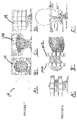
- FIGS. 11A-E illustrate an embodiment of the present invention utilized for prostate imaging.
- the PET inserts 14 are formed as PET panels 120 .
- the panels 120 can be composed of twelve individual modules 14 , for example, a 3 ⁇ 4 array, with each module 14 being approximately 5 cm ⁇ 5 cm in size.
- other numbers of modules, arrays and sizes of panels 120 and modules 14 may be implemented without departing from the spirit and scope of the present invention.
- FIG. 11A in one exemplary embodiment for prostate screening, four individual high resolution panel detectors 120 may be implemented, with two on the upper portion of the patient body and two on the lower portion.
- an endorectal sub-mm PET probe 122 my being inserted in the patient's anus and operates in coincidence with the two top PET panel modules 120 .
- FIG. 11D shows the response signals 124 that are generated between the panels 120 and probe 122 and through the prostate gland 126 . While RF coils 128 are pictured in FIGS. 11C-D , it will be understood that RF coils 128 are implemented in each embodiment shown in FIG. 11 and disposed between the PET panel detectors 120 and the patient's body.
- FIG. 12 illustrates an exemplary endorectal PET probe 122 utilized for prostate screening.
- the probe 122 is inserted in the external, generally cylindrical tube 130 , which provides mechanical means to stabilize the prostate during the PET/MRI scans.
- the tube 130 also incorporates also a special RF coil (not shown) to limit the interference of the PET sensor 132 (i.e., probe element) with the on-board input stage electronics 134 on MRI operation.
- Cables 136 connect the PET sensor 132 and the PET electronics 134 to the electronics remote from the MRI device.
- the overall system may be operated in a simultaneous PET/MRI mode.
- the PET probe 122 may be removed during MRI imaging (leaving the external tube 130 with the coil inside the patient), to minimize interference of the PET insert 122 with the MRI operation, therefore resulting in a sequential PET/MRI imaging.
- the external PET panel modules 120 (see FIG. 11 ) will stay in place during the MRI scans.
- FIGS. 13A-C illustrate conceptual diagrams of the endorectal PET probe sensor 122 based on a double-sided readout of the scintillation array, shown at 140 .
- the scintillator array 140 generally includes two top and bottom SiPM arrays, shown at 142 .
- the containment tube 130 (see FIG. 12 ) is shaped to have minimal cross-section (e.g., less than 35 mm in size).
- the same probe 122 could be also used intra-vaginally in the detection of selected gynecological cancers.
- FIGS. 14A-B illustrate an exemplary embodiment of the present invention utilized for vaginal imaging.
- FIGS. 14A-B shows PET panel modules 120 provided on the upper and lower portions of a patient to surround the patient in the vicinity of the pelvic region for vaginal screening.
- the PET panels 120 include four panel detectors (two on the top and two on the bottom), with each panel 120 built, in this example, with 12 individual MRI-compatible PET modules 14 , approximately 5 cm ⁇ 5 cm in size (preferably in a 3 ⁇ 4 array).
- other numbers of modules, arrays and sizes of panels 120 and modules 14 may be implemented without departing from the spirit and scope of the present invention.
- the system is divided into two sectors—top and bottom—each with two panel detectors 120 , for easy placement and adjustment around the patient inside the MRI scanner.
- the bottom panels 120 will need to be incorporated in the raised support for the patient.
- Each of the individual modules 14 is preferably made from a matrix of pixelated LYSO crystals coupled to an array of solid state Silicon Photo-Multipliers (“SiPMs”).
- SiPMs solid state Silicon Photo-Multipliers
- RF coils 128 are provided between the PET panels 120 and the patient's body.
- the PET probe 122 is not shown in FIG. 14 . However, similar to the prostate case, there are there are two possible variants of the PET probe 122 implementation intra-vaginally, or endorectally, one with and one without.
- FIGS. 15A-C illustrate an exemplary embodiment of the present invention utilized for cardiac imaging of the heart 150 and surrounding region.
- four imaging PET panels 120 are inserted in the MRI scanner to provide good angular coverage of the region of the heart.
- the PET panel modules 120 are provided on the upper and lower portions of a patient to surround the patient in the vicinity of the chest region for cardiac screening.
- the PET panels 120 include four panel detectors (two on the top and two on the bottom), with each panel 120 built, in this example, with 12 individual MRI-compatible PET modules 14 , approximately 5 cm ⁇ 5 cm in size (preferably in a 3 ⁇ 4 array).
- modules 120 and modules 14 may be implemented without departing from the spirit and scope of the present invention.
- the system is divided into two sectors—top and bottom—each with two panel detectors 120 , for easy placement and adjustment around the patient inside the MRI scanner.
- the bottom panels 120 will need to be incorporated in the raised support for the patient.
- Each of the individual modules 14 is preferably made from a matrix of pixelated LYSO crystals coupled to an array of solid state Silicon Photo-Multipliers (“SiPMs”).
- SiPMs solid state Silicon Photo-Multipliers
- RF coils 128 are provided between the PET panels 120 and the patient's body.
- FIGS. 16A-C illustrate exemplary embodiments of the present invention utilized for extremity (arm and leg) imaging.
- FIGS. 16A-B shows the PET modules 14 formed as a ring 160 and used for scanning a patient's leg, for example, around the knee area.
- FIG. 16C shows the PET modules 14 formed as a ring 160 and used for scanning a patient's arm, for example, around the shoulder area (for example looking for involved lymphatic nodes in case of breast cancer).
- FIGS. 16A-B illustrate a two-ring configuration
- FIG. 16C illustrates a three-ring configuration
- the RF coil 28 is provided between the PET modules 14 and the patient's body.
- any MRI scanner can be turned into a dedicated organ-specific (e.g., brain, breast, head/neck, extremities, prostate, OB/GYN, etc.) PET/MRI hybrid imager with no or minimal adaptation.
- a dedicated organ-specific (e.g., brain, breast, head/neck, extremities, prostate, OB/GYN, etc.) PET/MRI hybrid imager with no or minimal adaptation.
- the approval procedure is highly simplified (no modification to MRI scanner is performed) and only limited cooperation from the MRI manufacturer is required.
- the PET panels are composed of approximately 2′′ ⁇ 2′′ modules, with 5 cm ⁇ 5 cm SiPM photo sensors coupled to 50 cm ⁇ 50 cm ⁇ 10 mm LYSO scintillator arrays. These modules can be for, example arranged in 4 ⁇ 3 module panels. There are no electronics on board of the modules, except for the SiPM photo sensors.
- the SiPMs and passive readout circuitry (resistor and diode arrays) on board the modules are MRI compatible.
- the amplifier boards are located approximately 12 ft away outside the MRI bore, and are followed by, for example, the 64 ch DAQ box placed outside the MRI room, that is connected to computer via, for example, a USB2 link.
- An assembled and lightproof compact PET ring can be made out of, for example, twelve detector modules, composed of LYSO arrays and MPPC arrays. Such rings were prepared for studies in the 3 Tesla MRI. Long cables connect between the twelve modules and a set of three 4 ch electronics boards for twelve detector modules, which are disposed outside of the MRI bore.
- Construction of a prototype of the endorectal PET probe, as per the concept described above, can be effectuated, for example, using two 2′′ ⁇ 2′′ arrays of the Hamamatsu monolithic MPPC modules (SIMPs).
- the LYSO array of 24 ⁇ 24 pixels of 1 mm ⁇ 1 mm ⁇ 10 mm pixels (1 mm pitch) is coupled at both sides to SiPM arrays.
- This array from Proteus is optimized for the Depth of Interaction (“DOI”) double-sided operation.
- Teflon tape can cover a tight package with 8 monolithic MPPC modules and LYSO scintillation array having, for example, eight 20 cm long flexible flat cables with four of them bent by 180-degrees, to form a set of eight cables exiting outside of the probe and thus the patient.
- the amplifier boards will be attached to the ends of the cables, outside of the probe and the patient, thus minimizing the electronics' interference with the RF coil and the MRI.
- FIGS. 17A-C illustrate brain images taken from a brain phantom using an exemplary ring embodiment of the present invention, demonstrating the PET operation of the PET ring. Summed reconstructed images from a set of ten 1 mm slices from a multi-layer multi-compartmental brain phantom (see FIG. 17B ) filled with 450 microCurie F18 activity were taken.
- FIG. 17A illustrates a brain image a 30 minute run.
- FIG. 17C illustrates a brain image a 30 second run.
- the short run image ( FIG. 17C ) showed basically the same overall distribution pattern as the long image run ( FIG. 17A ), thus illustrating proper operation of the device.
- FIG. 18 illustrates twelve reconstructed 1 mm slices of the brain phantom obtained with the PET ring, further confirming proper PET imaging operation of the ring PET device.
- a brain phantom and a cylindrical “flood” phantom were used during measurements.
- the diameter of the active volume of the cylinder phantom was approximately 175 mm by about 50 mm in height.
- FIGS. 19A-C are brain images demonstrating the basic flood correction of the reconstructed images from the ring PET, as per the present inventive concept.
- the single vertical slice of the reconstructed brain phantom shows serious non-uniformities before the correction (see FIG. 19A ) using the image of the same vertical slice obtained with the uniformly filled cylinder phantom with water solution of radioactive-F18 (see FIG. 19B ).
- the image shown in FIG. 19C shows that practically all artifacts were corrected for.
- the first-order correction is performed by image division (using, for example, ImageJ software) of the (uncorrected) image slices obtained for the imaged object (such as, for example, phantom, or the patient's head, breast, extremity, etc.) by the corresponding slice images of the flood phantom.
- image division using, for example, ImageJ software
- the flood phantom slice images can be pre-processed before the image division takes place, for example by smoothing or filtering with an optimally selected filtering function, to limit the effect of statistical fluctuations in the flood images on the final images obtained as the result of this division.
- filtering may be also performed on the normalized images, i.e., the results of the image division.
- the geometrical response matrix includes the detector module response due to the fact that the detector ring is “broken” into modules/pieces with gaps between the modules. In addition, it corrects for the imperfections in the detector modules or the errors or in the calibration procedure. The latter effects can be seen as asymmetrical artifacts or non-uniformities in the detector module response. Also, at the edges of the imager's field of view, far from the center and approaching radially the detector modules, the effects of the depth of interaction (“DOI”) (typically not corrected for in a simplified detector design) introduce additional non-uniformities.
- DOI depth of interaction
- Series of flood images obtained for several diameter cylinders are stored in the image processing computer.
- the imaged objects e.g., head, brain, extremity, etc.
- a different flood with best-matched size to the imaged object is used for the above correction procedure, as will be understood by one skilled in the art.
- a twelve module PET ring was built according to the principles described herein of having no active electronics on board, and was inserted in the bore of the 3 Tesla Siemens MRI scanner.
- the electronics were placed in two locations: (1) amplifiers and power supplies (including the bias voltages for the operation of the SiPM based modules) were at the far ends of approximately 12 ft cables connecting at the input ends the detector modules, and placed outside the bore of the MRI scanner, close to the end of the patient table; and (2) in the electronics rack placed outside the MRI room having a data acquisition system (“DAQ”), a coincidence trigger unit with power supply, and a computer with data acquisition software.
- DAQ data acquisition system
- a coincidence trigger unit with power supply and a computer with data acquisition software.
- the PET ring was placed around the brain phantom. Inside the PET ring was placed a standard Siemens 3T Flex Large flexible RF coil. The coil is large enough to cover most of the patient's head, leaving opening for the face. Imaging of the brain phantom was performed with and without the flexible coil. In the latter case, the whole body RF coil was used.
- the PET ring electronics are inside the RF shielded box placed on a plastic MRI compatible cart next to the end of the patient's table.
- the electronics mobile cabinet was placed just outside the MRI room door with the flat cable going through the door.
- the cable connecting the PET ring electronics inside the MRI room and the cabinet in the operator room was exiting via the standard tube port provided in the wall connection panel.
- the data acquisition system the trigger module with power supply, and the computer/monitor.
- FIGS. 21A-B illustrate two MRI images from the above example, namely, 2 mm slices of the brain phantom using the T2 sequence.
- FIG. 21A shows, for comparison, using the RF body coil only.
- FIG. 21B shows using 3T Flex Large RF coil. In both cases the PET ring and the PET DAQ/computer system was fully powered.
- An exemplary imaging demonstration was performed with the PET ring insert imaging the brain PET phantom inserted inside the 3 Tesla MRI scanner.
- a flex RF coil was used and inserted inside the PET ring, between the ring and the phantom.
- Sequential and simultaneous imaging sessions were performed, using T2 and MPRAGE sequences.
- sequentially obtained PET and MRI phantom images we were able to produced/obtained in the same setting.
- FIGS. 22A-C show dual modality imaging performed in the 3 Tesla MRI scanner of the exemplary demonstration.
- FIG. 22A shows a 2 mm T2 MRI slice image
- FIG. 22C shows a 1 mm PET slice image of the brain phantom. These two slice images of the brain phantom are shown overlaid in FIG. 22B .
- the PET image was collected for 10 minutes.
- the position of the patient during MRI imaging can be, for example, supine (for example: brain, prostate, gynecological cancers, etc.), prone (for example: breast), but also upright (for example: patient sitting or standing during brain imaging) due to increasing availability of the inclined or vertical bore MRI scanners.
- MRI imaging in the upright position is enabling studies of the brain function that activates in the upright position.
- an example of clinical cases of interest is the study and assistance of the recovery in brains of stroke patients.
- the current inventive approach described herein is a relatively compact, lightweight wearable PET insert that can be “attached” mechanically and co-registered to the patient head, with a limited MRI-compatible mechanical support (to counterbalance the weight of the PET insert).
- the PET/MRI combination can be also upgraded to a PET/EEG/MRI variant.
- Such hybrid imaging can be beneficial in the imaging, for example, of epilepsy patients or in other conditions with strong electrical abnormalities in their brains, in addition to increased brain research opportunities.
- the EEG electrodes as usual, will be mounted directly on the head of the patient, with RF coils placed outside the EEG cap and inside the PET insert.
- an optical modality can be also added to the PET/MRI combination.
- an even smaller stomach inserted MR-compatible PET probe can be used and placed close (through the stomach wall) to the pancreas.
- the probe will operate with a set of panel detectors, as in the prostate and OB/GYN cases. This setup could also assist with other cases such as, for example, stomach cancers, etc.
- the PET inserts of the present invention can also, in principle, possess high timing characteristics and, therefore, can operate in the Time of Flight (“TOF”) mode with the advantage of improved S/N and higher image contrast.
- TOF Time of Flight
Landscapes
- Health & Medical Sciences (AREA)
- Physics & Mathematics (AREA)
- Engineering & Computer Science (AREA)
- Life Sciences & Earth Sciences (AREA)
- High Energy & Nuclear Physics (AREA)
- General Health & Medical Sciences (AREA)
- Nuclear Medicine, Radiotherapy & Molecular Imaging (AREA)
- Radiology & Medical Imaging (AREA)
- Theoretical Computer Science (AREA)
- Molecular Biology (AREA)
- General Physics & Mathematics (AREA)
- Medical Informatics (AREA)
- Pulmonology (AREA)
- Optics & Photonics (AREA)
- Veterinary Medicine (AREA)
- Pathology (AREA)
- Biomedical Technology (AREA)
- Heart & Thoracic Surgery (AREA)
- Condensed Matter Physics & Semiconductors (AREA)
- Surgery (AREA)
- Animal Behavior & Ethology (AREA)
- Public Health (AREA)
- Biophysics (AREA)
- Spectroscopy & Molecular Physics (AREA)
- Neurology (AREA)
- Neurosurgery (AREA)
- Dentistry (AREA)
- Oral & Maxillofacial Surgery (AREA)
- Magnetic Resonance Imaging Apparatus (AREA)
- Nuclear Medicine (AREA)
Abstract
Description
-
- The PET ring of the present invention very tightly surrounds the patient's head, without a “stand-off” distance. For a long time, this gap distance was assumed to be necessary to assure proper operation of the PET reconstruction software. However, studies by the present inventors have proved that it is possible to get suitable performance without the gap distance once one carries out proper calibration of the imager response.
- The present invention does not use specialized MRI RF coils, which are typically considered the standard and judged to be the necessary approach. In contrast, the present invention rather performs imaging with: (1) the whole body RF coil built into the MRI scanner; or (2) implementation of the standard flexible coils that are typically part of a set of coils delivered with the scanner and/or available from the MRI scanner manufacturer.
-
- Increased detector efficiency (e.g., design, close geometry, etc.).
- Better collimators (e.g., single gamma, SPECT, etc.).
- Improvement in radio imaging agents (e.g., biology, specificity, uptake, etc.).
- Optimization of reconstruction software and analytical algorithms.
- Task-specific dose requirements as opposed to generic standard doses.
- Indirectly, through dual modality imaging PET/MRI and SPECT/MRI with MRI modality, providing structural information (e.g., less demand on high resolution/high statistics in PET or SPECT images).
-
- Improvements in collimators and selection of optimal collimators for the task.
- Increase in angular coverage.
- Simultaneous multiple views, for example, double-sided imaging in breast images.
- More specific imaging agents with higher diseased tissue/healthy tissue uptake ratios.
- SPECT inserts in MRI with MRI providing the co-registered anatomic information, relaxing the demand for higher statistics in SPECT images.
-
- A compact PET machine, which could stand-alone.
- The ability to work with current MRI machines.
- Cheaper than current MRI/PET scanners.
- Inserts can be organ specific, eliminating full body scan.
-
- K. J. Hong, Y. Choi, J. Kang, W. Hu, J. H. Jung, B. J. Min, Y. H. Chung, and C. Jackson: Performance evaluation of a PET detector consists of a LYSO array coupled to a 4×4 array of large-size GAPD for MR compatible imaging, J. Instrum., vol. 6, P05012, 2011.
- J. Kang, Y. Choi, K. J. Hong, J. H. Jung, W. Hu, Y. S. Huh, H. K. Lim, and B-T Kim: A feasibility study of photosensor charge signal transmission to preamplifier using long cable for development of hybrid PET-MRI, Med. Phys., vol. 37, pp. 5655-5664, 2010.
- J. H. Jung, Y. Choi, K. J. Hong, W. Hu, J. Kang, B. J. Min, S. H. Shin, H. K. Lim, Y. S. Huh, and E. J. Kim: Development of a position decoder circuit for PET consisting of GAPD arrays, Nucl. Instr. and Meth., vol. A 621, pp. 310-315, 2010.
- W. Hu, Y. Choi, K. J. Hong, J. Kang, J. H. Jung, Y. S. Huh, H. K. Lim, S. S. Kim, and B. T. Kim: A simple and improved digital timing method for positron emission tomography, Nucl. Instr. and Meth., vol. A 622, pp. 219-224, 2010.
Claims (19)
Priority Applications (1)
| Application Number | Priority Date | Filing Date | Title |
|---|---|---|---|
| US13/827,557 US10634747B2 (en) | 2013-03-14 | 2013-03-14 | Apparatus and implementation method of a set of universal compact portable MR-compatible PET inserts to convert whole-body MRI scanners into organ-specific hybrid PET/MRI imagers |
Applications Claiming Priority (1)
| Application Number | Priority Date | Filing Date | Title |
|---|---|---|---|
| US13/827,557 US10634747B2 (en) | 2013-03-14 | 2013-03-14 | Apparatus and implementation method of a set of universal compact portable MR-compatible PET inserts to convert whole-body MRI scanners into organ-specific hybrid PET/MRI imagers |
Publications (2)
| Publication Number | Publication Date |
|---|---|
| US20140275965A1 US20140275965A1 (en) | 2014-09-18 |
| US10634747B2 true US10634747B2 (en) | 2020-04-28 |
Family
ID=51530402
Family Applications (1)
| Application Number | Title | Priority Date | Filing Date |
|---|---|---|---|
| US13/827,557 Expired - Fee Related US10634747B2 (en) | 2013-03-14 | 2013-03-14 | Apparatus and implementation method of a set of universal compact portable MR-compatible PET inserts to convert whole-body MRI scanners into organ-specific hybrid PET/MRI imagers |
Country Status (1)
| Country | Link |
|---|---|
| US (1) | US10634747B2 (en) |
Cited By (3)
| Publication number | Priority date | Publication date | Assignee | Title |
|---|---|---|---|---|
| WO2021113957A1 (en) * | 2019-12-09 | 2021-06-17 | Sino Canada Health Institute Inc. | Method for monitoring pet readout positions using mri fiducials |
| US11481934B2 (en) * | 2018-10-10 | 2022-10-25 | New York University | System, method, and computer-accessible medium for generating magnetic resonance imaging-based anatomically guided positron emission tomography reconstruction images with a convolutional neural network |
| EP4176816A1 (en) * | 2021-11-08 | 2023-05-10 | Positrigo AG | Detector for a positron emission tomography (pet)-scanning device |
Families Citing this family (11)
| Publication number | Priority date | Publication date | Assignee | Title |
|---|---|---|---|---|
| WO2014064286A1 (en) * | 2012-10-26 | 2014-05-01 | Koninklijke Philips N.V. | Reducing interference in a combined system comprising an mri system and a non-mr imaging system |
| US20140195954A1 (en) * | 2013-01-09 | 2014-07-10 | Siemens Medical Solutions Usa, Inc. | Accessories as Workflow Priors in Medical Systems |
| JP6124216B2 (en) * | 2013-10-30 | 2017-05-10 | 国立研究開発法人量子科学技術研究開発機構 | Helmet type PET equipment |
| US9606245B1 (en) | 2015-03-24 | 2017-03-28 | The Research Foundation For The State University Of New York | Autonomous gamma, X-ray, and particle detector |
| US10806416B2 (en) * | 2015-08-05 | 2020-10-20 | Shanghai United Imaging Healthcare Co., Ltd. | PET/MRI insert system |
| ES2634027B1 (en) * | 2016-02-26 | 2018-07-02 | General Equipment For Medical Imaging, S.A. | Mobile molecular imaging system and intervention system comprising it |
| ES2644251B1 (en) * | 2016-04-25 | 2018-10-10 | General Equipment For Medical Imaging, S.A. | A PET IMAGE DEVICE DEDICATED TO THE OBSERVATION OF THE BRAIN |
| US10983185B2 (en) * | 2017-11-22 | 2021-04-20 | General Electric Company | RF coil array for an MRI system |
| EP4058817A4 (en) * | 2019-11-13 | 2023-12-20 | Sino Canada Health Institute Inc. | BRAINPET SYSTEM FOR SIMULTANEOUS MRI AND PET IMAGING |
| WO2021211941A1 (en) * | 2020-04-16 | 2021-10-21 | West Virginia University | Mobile configurable pet for in-room bedside imaging |
| TWI908046B (en) * | 2023-04-27 | 2025-12-11 | 中央研究院 | An imaging system for use in a positron emission tomography or single photon emission computed tomography and a multi-angular image reconstruction methode thereof |
Citations (4)
| Publication number | Priority date | Publication date | Assignee | Title |
|---|---|---|---|---|
| US20100187424A1 (en) * | 2009-01-23 | 2010-07-29 | Jefferson Science Associates, Llc | Dedicated mobile high resolution prostate PET imager with an insertable transrectal probe |
| US7884331B2 (en) | 2008-09-19 | 2011-02-08 | Jefferson Science Associates Llc | Compact and mobile high resolution PET brain imager |
| US20110224534A1 (en) * | 2010-03-09 | 2011-09-15 | National Institute Of Radiological Sciences | Pet/mri device, pet device, and image reconstruction system |
| US20120136237A1 (en) * | 2009-01-07 | 2012-05-31 | Consejo Superior De Investigaciones Cientificas | Compact, hybrid and integrated gamma/rf system used to form simultaneous pet or spect and mr images |
-
2013
- 2013-03-14 US US13/827,557 patent/US10634747B2/en not_active Expired - Fee Related
Patent Citations (4)
| Publication number | Priority date | Publication date | Assignee | Title |
|---|---|---|---|---|
| US7884331B2 (en) | 2008-09-19 | 2011-02-08 | Jefferson Science Associates Llc | Compact and mobile high resolution PET brain imager |
| US20120136237A1 (en) * | 2009-01-07 | 2012-05-31 | Consejo Superior De Investigaciones Cientificas | Compact, hybrid and integrated gamma/rf system used to form simultaneous pet or spect and mr images |
| US20100187424A1 (en) * | 2009-01-23 | 2010-07-29 | Jefferson Science Associates, Llc | Dedicated mobile high resolution prostate PET imager with an insertable transrectal probe |
| US20110224534A1 (en) * | 2010-03-09 | 2011-09-15 | National Institute Of Radiological Sciences | Pet/mri device, pet device, and image reconstruction system |
Non-Patent Citations (12)
Cited By (5)
| Publication number | Priority date | Publication date | Assignee | Title |
|---|---|---|---|---|
| US11481934B2 (en) * | 2018-10-10 | 2022-10-25 | New York University | System, method, and computer-accessible medium for generating magnetic resonance imaging-based anatomically guided positron emission tomography reconstruction images with a convolutional neural network |
| WO2021113957A1 (en) * | 2019-12-09 | 2021-06-17 | Sino Canada Health Institute Inc. | Method for monitoring pet readout positions using mri fiducials |
| US12558052B2 (en) | 2019-12-09 | 2026-02-24 | Sino Canada Health Institute Inc. | Method for monitoring PET readout positions using MRI fiducials |
| EP4176816A1 (en) * | 2021-11-08 | 2023-05-10 | Positrigo AG | Detector for a positron emission tomography (pet)-scanning device |
| WO2023078842A1 (en) * | 2021-11-08 | 2023-05-11 | Positrigo Ag | Detector for a positron emission tomography (pet)-scanning device |
Also Published As
| Publication number | Publication date |
|---|---|
| US20140275965A1 (en) | 2014-09-18 |
Similar Documents
| Publication | Publication Date | Title |
|---|---|---|
| US10634747B2 (en) | Apparatus and implementation method of a set of universal compact portable MR-compatible PET inserts to convert whole-body MRI scanners into organ-specific hybrid PET/MRI imagers | |
| US12029597B2 (en) | PET/MRI insert system | |
| Pichler et al. | Multimodal imaging approaches: pet/ct and pet/mri | |
| Townsend et al. | Combining anatomy and function: the path to true image fusion | |
| KR100914429B1 (en) | Combined positron emission tomography pet and magnetic resonance imaging mri apparatus | |
| JP5593330B2 (en) | Compact, hybrid and integrated gamma / RF system for simultaneous PET or SPECT and MR imaging | |
| Pichler et al. | Positron emission tomography/magnetic resonance imaging: the next generation of multimodality imaging? | |
| JP6402155B2 (en) | Radiation therapy planning and follow-up system using large bore nuclear and magnetic resonance imaging or large bore CT and magnetic resonance imaging | |
| US6449331B1 (en) | Combined PET and CT detector and method for using same | |
| KR100878881B1 (en) | Integrated PET / CT System | |
| Zaidi et al. | An outlook on future design of hybrid PET/MRI systems | |
| US9029787B2 (en) | Multi-purpose PET device | |
| RU2634622C2 (en) | Protocol with dose optimisation for attenuation correction and location determination on hybrid scanners | |
| JP5750684B2 (en) | PET-MRI equipment | |
| US20080135769A1 (en) | Attenuation correction of pet image using image data acquired with an mri system | |
| US20030090267A1 (en) | Apparatus for combined nuclear imaging and magnetic resonance imaging, and method thereof | |
| JP6130840B2 (en) | Adaptive dual path target reconstruction and acquisition | |
| Sanaat et al. | The quest for multifunctional and dedicated PET instrumentation with irregular geometries | |
| Aiello et al. | Hybrid PET/MRI Methodology | |
| CN103619246B (en) | Medical image diagnostic device | |
| CN101132731A (en) | Combined PET/MR Imaging System and APD-Based PET Detector for Simultaneous PET/MR Imaging | |
| CN113785211A (en) | BrainPET system for simultaneous MRI and PET imaging | |
| KR101051051B1 (en) | Actuator of positron emission tomography equipment used in the fusion system of magnetic resonance imaging and positron emission tomography | |
| Bauer et al. | Development of a ring PET insert for MRI | |
| Kapila et al. | The advent of MR/PET Imaging |
Legal Events
| Date | Code | Title | Description |
|---|---|---|---|
| AS | Assignment |
Owner name: NATIONAL INSTITUTES OF HEALTH (NIH), U.S. DEPT. OF Free format text: CONFIRMATORY LICENSE;ASSIGNOR:WEST VIRGINIA UNIVERSITY;REEL/FRAME:030049/0102 Effective date: 20130318 Owner name: NATIONAL INSTITUTES OF HEALTH (NIH), U.S. DEPT. OF HEALTH AND HUMAN SERVICES (DHHS), U.S. GOVERNMENT, MARYLAND Free format text: CONFIRMATORY LICENSE;ASSIGNOR:WEST VIRGINIA UNIVERSITY;REEL/FRAME:030049/0102 Effective date: 20130318 |
|
| AS | Assignment |
Owner name: WEST VIRGINIA UNIVERSITY, WEST VIRGINIA Free format text: ASSIGNMENT OF ASSIGNORS INTEREST;ASSIGNORS:MAJEWSKI, STANISLAW;PROFFITT, JAMES;LEWIS, JAMES W.;AND OTHERS;SIGNING DATES FROM 20120814 TO 20120821;REEL/FRAME:030188/0384 |
|
| STPP | Information on status: patent application and granting procedure in general |
Free format text: FINAL REJECTION MAILED |
|
| STPP | Information on status: patent application and granting procedure in general |
Free format text: DOCKETED NEW CASE - READY FOR EXAMINATION |
|
| STPP | Information on status: patent application and granting procedure in general |
Free format text: NOTICE OF ALLOWANCE MAILED -- APPLICATION RECEIVED IN OFFICE OF PUBLICATIONS |
|
| ZAAA | Notice of allowance and fees due |
Free format text: ORIGINAL CODE: NOA |
|
| ZAAB | Notice of allowance mailed |
Free format text: ORIGINAL CODE: MN/=. |
|
| STPP | Information on status: patent application and granting procedure in general |
Free format text: PUBLICATIONS -- ISSUE FEE PAYMENT RECEIVED |
|
| STCF | Information on status: patent grant |
Free format text: PATENTED CASE |
|
| FEPP | Fee payment procedure |
Free format text: MAINTENANCE FEE REMINDER MAILED (ORIGINAL EVENT CODE: REM.); ENTITY STATUS OF PATENT OWNER: SMALL ENTITY |
|
| LAPS | Lapse for failure to pay maintenance fees |
Free format text: PATENT EXPIRED FOR FAILURE TO PAY MAINTENANCE FEES (ORIGINAL EVENT CODE: EXP.); ENTITY STATUS OF PATENT OWNER: SMALL ENTITY |
|
| STCH | Information on status: patent discontinuation |
Free format text: PATENT EXPIRED DUE TO NONPAYMENT OF MAINTENANCE FEES UNDER 37 CFR 1.362 |
|
| FP | Lapsed due to failure to pay maintenance fee |
Effective date: 20240428 |