US10629006B2 - Wireless sensor system for a vehicle - Google Patents
Wireless sensor system for a vehicle Download PDFInfo
- Publication number
- US10629006B2 US10629006B2 US15/565,148 US201615565148A US10629006B2 US 10629006 B2 US10629006 B2 US 10629006B2 US 201615565148 A US201615565148 A US 201615565148A US 10629006 B2 US10629006 B2 US 10629006B2
- Authority
- US
- United States
- Prior art keywords
- sensor
- data
- vehicle
- sensor node
- gateway
- Prior art date
- Legal status (The legal status is an assumption and is not a legal conclusion. Google has not performed a legal analysis and makes no representation as to the accuracy of the status listed.)
- Active, expires
Links
- 238000013523 data management Methods 0.000 claims abstract description 7
- 238000012517 data analytics Methods 0.000 claims abstract description 3
- 238000004891 communication Methods 0.000 claims description 25
- 238000007726 management method Methods 0.000 claims description 16
- 230000005540 biological transmission Effects 0.000 claims description 14
- 238000000034 method Methods 0.000 claims description 13
- 238000012360 testing method Methods 0.000 claims description 9
- 238000012544 monitoring process Methods 0.000 claims description 7
- 238000007405 data analysis Methods 0.000 claims description 6
- 238000013500 data storage Methods 0.000 claims description 6
- 238000012546 transfer Methods 0.000 claims description 4
- CNKHSLKYRMDDNQ-UHFFFAOYSA-N halofenozide Chemical compound C=1C=CC=CC=1C(=O)N(C(C)(C)C)NC(=O)C1=CC=C(Cl)C=C1 CNKHSLKYRMDDNQ-UHFFFAOYSA-N 0.000 claims description 2
- 238000005070 sampling Methods 0.000 claims description 2
- 238000009434 installation Methods 0.000 description 8
- 238000000576 coating method Methods 0.000 description 7
- 239000011248 coating agent Substances 0.000 description 5
- 238000013480 data collection Methods 0.000 description 5
- 238000013461 design Methods 0.000 description 4
- 238000012423 maintenance Methods 0.000 description 3
- RZVHIXYEVGDQDX-UHFFFAOYSA-N 9,10-anthraquinone Chemical compound C1=CC=C2C(=O)C3=CC=CC=C3C(=O)C2=C1 RZVHIXYEVGDQDX-UHFFFAOYSA-N 0.000 description 2
- 238000010276 construction Methods 0.000 description 2
- 238000005259 measurement Methods 0.000 description 2
- 238000010521 absorption reaction Methods 0.000 description 1
- 230000001133 acceleration Effects 0.000 description 1
- 238000007792 addition Methods 0.000 description 1
- 230000004075 alteration Effects 0.000 description 1
- 238000004458 analytical method Methods 0.000 description 1
- 230000008901 benefit Effects 0.000 description 1
- 230000008859 change Effects 0.000 description 1
- 230000001010 compromised effect Effects 0.000 description 1
- 230000000593 degrading effect Effects 0.000 description 1
- 238000011161 development Methods 0.000 description 1
- 238000011156 evaluation Methods 0.000 description 1
- 239000002828 fuel tank Substances 0.000 description 1
- 238000010438 heat treatment Methods 0.000 description 1
- 239000000463 material Substances 0.000 description 1
- 239000002184 metal Substances 0.000 description 1
- 238000012986 modification Methods 0.000 description 1
- 230000004048 modification Effects 0.000 description 1
- 230000008439 repair process Effects 0.000 description 1
- 238000012827 research and development Methods 0.000 description 1
- 238000012384 transportation and delivery Methods 0.000 description 1
Images


Classifications
-
- G—PHYSICS
- G07—CHECKING-DEVICES
- G07C—TIME OR ATTENDANCE REGISTERS; REGISTERING OR INDICATING THE WORKING OF MACHINES; GENERATING RANDOM NUMBERS; VOTING OR LOTTERY APPARATUS; ARRANGEMENTS, SYSTEMS OR APPARATUS FOR CHECKING NOT PROVIDED FOR ELSEWHERE
- G07C5/00—Registering or indicating the working of vehicles
- G07C5/008—Registering or indicating the working of vehicles communicating information to a remotely located station
-
- B—PERFORMING OPERATIONS; TRANSPORTING
- B64—AIRCRAFT; AVIATION; COSMONAUTICS
- B64D—EQUIPMENT FOR FITTING IN OR TO AIRCRAFT; FLIGHT SUITS; PARACHUTES; ARRANGEMENT OR MOUNTING OF POWER PLANTS OR PROPULSION TRANSMISSIONS IN AIRCRAFT
- B64D45/00—Aircraft indicators or protectors not otherwise provided for
-
- B—PERFORMING OPERATIONS; TRANSPORTING
- B64—AIRCRAFT; AVIATION; COSMONAUTICS
- B64F—GROUND OR AIRCRAFT-CARRIER-DECK INSTALLATIONS SPECIALLY ADAPTED FOR USE IN CONNECTION WITH AIRCRAFT; DESIGNING, MANUFACTURING, ASSEMBLING, CLEANING, MAINTAINING OR REPAIRING AIRCRAFT, NOT OTHERWISE PROVIDED FOR; HANDLING, TRANSPORTING, TESTING OR INSPECTING AIRCRAFT COMPONENTS, NOT OTHERWISE PROVIDED FOR
- B64F5/00—Designing, manufacturing, assembling, cleaning, maintaining or repairing aircraft, not otherwise provided for; Handling, transporting, testing or inspecting aircraft components, not otherwise provided for
- B64F5/60—Testing or inspecting aircraft components or systems
-
- G—PHYSICS
- G07—CHECKING-DEVICES
- G07C—TIME OR ATTENDANCE REGISTERS; REGISTERING OR INDICATING THE WORKING OF MACHINES; GENERATING RANDOM NUMBERS; VOTING OR LOTTERY APPARATUS; ARRANGEMENTS, SYSTEMS OR APPARATUS FOR CHECKING NOT PROVIDED FOR ELSEWHERE
- G07C5/00—Registering or indicating the working of vehicles
- G07C5/08—Registering or indicating performance data other than driving, working, idle, or waiting time, with or without registering driving, working, idle or waiting time
- G07C5/0816—Indicating performance data, e.g. occurrence of a malfunction
-
- G—PHYSICS
- G07—CHECKING-DEVICES
- G07C—TIME OR ATTENDANCE REGISTERS; REGISTERING OR INDICATING THE WORKING OF MACHINES; GENERATING RANDOM NUMBERS; VOTING OR LOTTERY APPARATUS; ARRANGEMENTS, SYSTEMS OR APPARATUS FOR CHECKING NOT PROVIDED FOR ELSEWHERE
- G07C5/00—Registering or indicating the working of vehicles
- G07C5/08—Registering or indicating performance data other than driving, working, idle, or waiting time, with or without registering driving, working, idle or waiting time
- G07C5/0841—Registering performance data
-
- H—ELECTRICITY
- H04—ELECTRIC COMMUNICATION TECHNIQUE
- H04L—TRANSMISSION OF DIGITAL INFORMATION, e.g. TELEGRAPHIC COMMUNICATION
- H04L67/00—Network arrangements or protocols for supporting network services or applications
- H04L67/01—Protocols
- H04L67/12—Protocols specially adapted for proprietary or special-purpose networking environments, e.g. medical networks, sensor networks, networks in vehicles or remote metering networks
-
- H—ELECTRICITY
- H04—ELECTRIC COMMUNICATION TECHNIQUE
- H04Q—SELECTING
- H04Q9/00—Arrangements in telecontrol or telemetry systems for selectively calling a substation from a main station, in which substation desired apparatus is selected for applying a control signal thereto or for obtaining measured values therefrom
-
- B—PERFORMING OPERATIONS; TRANSPORTING
- B64—AIRCRAFT; AVIATION; COSMONAUTICS
- B64D—EQUIPMENT FOR FITTING IN OR TO AIRCRAFT; FLIGHT SUITS; PARACHUTES; ARRANGEMENT OR MOUNTING OF POWER PLANTS OR PROPULSION TRANSMISSIONS IN AIRCRAFT
- B64D45/00—Aircraft indicators or protectors not otherwise provided for
- B64D2045/0085—Devices for aircraft health monitoring, e.g. monitoring flutter or vibration
-
- G—PHYSICS
- G01—MEASURING; TESTING
- G01S—RADIO DIRECTION-FINDING; RADIO NAVIGATION; DETERMINING DISTANCE OR VELOCITY BY USE OF RADIO WAVES; LOCATING OR PRESENCE-DETECTING BY USE OF THE REFLECTION OR RERADIATION OF RADIO WAVES; ANALOGOUS ARRANGEMENTS USING OTHER WAVES
- G01S19/00—Satellite radio beacon positioning systems; Determining position, velocity or attitude using signals transmitted by such systems
- G01S19/01—Satellite radio beacon positioning systems transmitting time-stamped messages, e.g. GPS [Global Positioning System], GLONASS [Global Orbiting Navigation Satellite System] or GALILEO
- G01S19/13—Receivers
-
- H—ELECTRICITY
- H01—ELECTRIC ELEMENTS
- H01Q—ANTENNAS, i.e. RADIO AERIALS
- H01Q1/00—Details of, or arrangements associated with, antennas
- H01Q1/27—Adaptation for use in or on movable bodies
- H01Q1/28—Adaptation for use in or on aircraft, missiles, satellites, or balloons
- H01Q1/282—Modifying the aerodynamic properties of the vehicle, e.g. projecting type aerials
- H01Q1/283—Blade, stub antennas
-
- H—ELECTRICITY
- H04—ELECTRIC COMMUNICATION TECHNIQUE
- H04W—WIRELESS COMMUNICATION NETWORKS
- H04W84/00—Network topologies
- H04W84/18—Self-organising networks, e.g. ad-hoc networks or sensor networks
-
- H—ELECTRICITY
- H04—ELECTRIC COMMUNICATION TECHNIQUE
- H04W—WIRELESS COMMUNICATION NETWORKS
- H04W88/00—Devices specially adapted for wireless communication networks, e.g. terminals, base stations or access point devices
- H04W88/16—Gateway arrangements
Definitions
- This invention relates to a wireless sensor system, for use on high performance vehicles such as aircraft, that includes a plurality of sensor nodes of various types and on-board data collection, storage, transmission, command and control and system integrity checking systems.
- the wireless sensor system is able to be self-powered, and attached to, or removed from, the high performance vehicle, with a minimum of vehicle downtime, and without causing any damage to the external surface coating of the vehicle.
- High performance vehicles for example high performance aircraft and aircraft undergoing testing and research and development, require a reliable, accurate and robust sensor and telemetry system in order to provide real-time operational condition feedback of the measurement data collected by the sensors.
- This data may be sent as continuous telemetry and/or collected in a central data collection unit for subsequent downloading.
- the data collected may be stored within the sensor itself, and subsequently transmitted to the central data collection unit at a specific time. Or it may be required to collect data individually from each sensor using a portable computer.
- current sensors typically require wiring to at least provide power to the sensor, and typically also to provide a path for the data acquired by the sensor to be sent to a separate data logger at a sufficient data transfer rate.
- the fitting of wired sensors can take weeks, or even months to install and commission. This adds significantly to the cost, both direct and indirect, related to having such a high value asset out of commission during the fitting and commissioning phases.
- Traditional wired sensors may be smaller than their non-wired counterparts, but when wired sensors have the advantage with size, they have the disadvantage of adding the weight of the associated wiring that is required for them to operate. It is not uncommon for an installed system to consist of several kilograms of wiring. Most often, the aircraft structure needs to be permanently modified to accommodate the sensing system and its associated equipment and wiring. When an aircraft is modified in this way, it often needs to have its airworthiness re-certified. Air-worthiness certification is both time consuming and very costly.
- modified aircraft often become “orphan aircraft” because of their unique modified structures and require individualised maintenance and sustainment plans which are costly and inefficient, thereby making them a burden on aircraft maintenance resources and scheduling. All this substantially increases the cost and time associated with acquiring real time flight performance data, both in direct costs, and in the ancillary costs surrounding specialised maintenance and recertification.
- Orange wired aircraft are significantly more expensive than regular aircraft. Due to this significant extra cost, both in acquiring and maintaining them, they are often minimally used to preserve their integrity, and to reduce their wear and tear, and to keep the aircraft within its airworthiness lifespan for as long as possible. This type of special treatment often means that there is a disconnect between the flight characteristics of an orange wired aircraft over that of a regular aircraft of the same make and model. The data acquired from the operation of orange wired aircraft may not be truly representative of the operations of the entire regular fleet.
- stealth is now a major design consideration in many designs of military aircraft, particularly high performance military aircraft.
- Two critical factors that directly relate to the stealthiness of a particular aircraft design are its shape and the type of coating on the skin of the aircraft.
- Many advanced coatings have either been developed already, or are under development, that provide a high level of RADAR signal absorption, and this coating cannot be either removed or damaged in relation to the installation of, or removal of, any of the sensors and/or its ancillary equipment.
- the installation of the sensors and/or its ancillary equipment cannot significantly alter the shape of the aircraft so that its stealth performance is compromised in any way.
- the present invention is a wireless sensor and telemetry system for use on a vehicle such as an aircraft including:
- the gateway is capable of receiving operational control signals and thereby configuring the wireless sensor and telemetry system in accordance with the received operational control signals, and the gateway is capable of alerting a person, or persons, if any one of the at least one sensor node, or the gateway itself, is no longer capable of functioning within acceptable operational parameters.
- the gateway is capable of receiving the acquired data from all the sensor nodes in the system, and it is capable of storing that acquired data or streaming that acquired data via a telemetry system, either continuously, or in batches, to a person or persons within the vehicle, or remote from the vehicle.
- the gateway includes:
- the sensor node comes in a variety of shapes, sizes and weights, and may include one or more sensors within the node that are each capable of acquiring a specific type of data relating to the operational performance of, or structural condition of, the vehicle.
- the appropriate sensor node type is selectable from a range of available sensor nodes so that the sensor node can be attached to the vehicle either internally to the vehicle's frame, or upon the outer skin of the vehicle, depending upon the particular types(s) of operational performance and/or structural condition of the vehicle that is being monitored by the sensor(s) in the sensor node.
- the sensor nodes that are selected from the range of available sensor nodes, for use on any of the control surfaces of the vehicle, feature light weight and a low profile construction, so as to not significantly interrupt the operational performance of the vehicle during its operation.
- each of the sensor nodes used in the system works in conjunction with fastening means that is designed so that the particular sensor node type can be attached to, and removed from, the vehicle without damaging the vehicle's outer surface, or its frame, and wherein the fastener means enables each sensor type to be fastened to, or removed from, the vehicle within an acceptable amount of time, without the need for special tools, or for the vehicle to be moved to a specialised installation location.
- each sensor node type includes wireless data transmission and receiving means, and these means enable the particular sensor node to operate in accordance with specific operational instructions given to it from the gateway, or directly from a remote management system, and to transmit the sensor data it acquires while in use, to the gateway, or directly to the remote management system.
- each sensor node type has an autonomous power supply.
- each sensor node is capable of determining in real time what the most appropriate sensor within the node is at any particular time during the operation of the vehicle so that the best quality data can be acquired by that sensor node at any given time.
- each sensor node is able to self-calibrate its sensors and report any sensor that is not functioning within acceptable performance parameters as pre-set, or subsequently set, by the operator of the system.
- each sensor node is modular, thereby allowing an operator to provision a sensor node with at least one sensor type, so that the node is capable of acquiring a pre-determined set of sensor data that conforms with the type of test(s) being conducted during the operation of the vehicle.
- each sensor node will include heating means so that the temperature of the sensors within the node does not drop below a set minimum temperature.
- At least one of the types of sensor nodes that is selectable from the range of sensor nodes includes a flexible body that enables the sensor to be shaped so that it closely conforms to the surface shape of the part of the vehicle to which it has been fastened.
- the types of surface include, by way of example, rotating shafts, external fuel tanks, and ordinance mounting and delivery systems.
- the sensor data collection and analysis system includes a user interface within the crew cabin, such as the cockpit on an aircraft, and this data collection and analysis system is usable by the on-board operators of the vehicle.
- both the user interface within the crew cabin, and any external remote user interface includes a graphical user interface.
- the remote management user interface for the onboard sensor system and telemetry includes at least one computer wherein a remote operator or operators can wirelessly communicate with, and manage the operation of, the sensor and telemetry system using the at least one computer, and wherein the remote management system allows the remote operator or operators to communicate directly with the gateway, and/or each sensor node in the sensor and telemetry system.
- the remote management system manages all aspects of the operation of the sensor and telemetry system, including, but not limited to:
- the system is able to communicate wirelessly in real-time on up to 150 channels in deployed sensor nodes simultaneously, as well as accepting live streaming data from these nodes at sample rates suitable for high performance vehicle testing.
- the system is able to buffer data in the event of a loss of wireless communications, and transmit the buffered data when wireless communication resume, while maintaining data integrity.
- the sensor system shall be connected to the vehicles power supply system.
- the power supply for at least a part of the sensor system is autonomous.
- each sensor node used in the system is able to be attached directly onto a coated surface of the vehicle, and the attachment means enables the installation and removal of each sensor node to or from the surface without damaging the integrity of the coated surface.
- At least one of the sensor node types shall be capable for use while mounted to an external surface of the vehicle during operation at supersonic speeds up to Mach 2.
- the present invention includes a method of providing a sensor and telemetry system to a vehicle including the steps of:
- the method includes a step of enabling the gateway to condition monitor the operational performance of the system, including each of the sensor nodes, and the sensor types housed within each one, the status of the wireless sensor real-time data transmission, so that an alert may be generated if any of the components within the system is no longer capable of functioning within acceptable operational parameters.
- the method includes a step of providing the gateway with storage means that enables the gateway to store the acquired data it receives from the sensor nodes, and wirelessly streaming it, either in batches, or continuously, to a user of the system, or to store the acquired data, in the event of a loss of wireless communications between the gateway and the user interface, and resume the data transmission once the communication link is restored.
- the method includes a step of providing the system with an accurate GPS and time keeping system so that all data acquired has its associated location and time data recorded in the system.
- the method includes a step of providing at least one type of sensor node with a deformable housing that thereby allows a user to deform the housing to make the sensor node as low profile as possible, and to enable the shape of the deformation to closely match the contours of the surface upon which the sensor node is affixed.
- the method includes a step of providing a fastening means that is adapted to enable a sensor node to be affixed to, and subsequently removed from, a surface on the vehicle, without either degrading the surface material, or any coating applied thereto, and without the need for special tools, or for the need to move the vehicle to a specialized installation or removal location.
- the method includes a step of providing the system with an autonomous power supply system.
- the method includes a step of providing the system with the wireless transmission means to enable up to 150 channels in deployed sensor nodes to communicate wirelessly and simultaneously in real-time.
- FIG. 1 is a top view of a typical high performance vehicle with an array of sensors and ancillary equipment installed in accordance with the present invention.
- FIG. 2 is a schematic view of a typical vehicle, in this example an aircraft, in flight and showing the wireless data communications.
- FIG. 3 is a schematic of a couple of sensors attached to the leading edge of an aircraft wing, and also a sensor attached to the surface of a control surface for the aircraft.
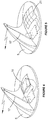
- FIGS. 4-7 are various embodiments of a wireless sensor nodes used in conjunction with the wireless sensor system.
- FIG. 1 we can see a schematic of the wireless sensor and telemetry system that is the subject of the present invention.
- a gateway 3 in this embodiment carried under starboard wing, and a plurality of sensor nodes 5 .
- the gateway 3 and each sensor node 5 is wirelessly connected together for two-way data communication. This two-way communication may be directly between an individual sensor node 5 and the gateway 3 , or a cluster of sensor nodes 5 and the gateway 3 .
- a cockpit mounted sensor system monitoring and management interface 7 we are also shown.
- FIG. 2 we are shown another schematic of the overall sensor system.
- the aircraft 1 has a plurality of sensor nodes 5 fitted to strategic positions on the airframe and on flight control surfaces. Each sensor node, and/or clusters of sensor nodes are in two-way wireless communication with the sensor gateway 3 , this time located under the port wing of the aircraft.
- the sensor gateway 3 is designed to fit to a standard ordinance/equipment mounting point on the aircraft's airframe.
- the sensor gateway 3 is in two-way wireless communication with the cockpit mounted management interface 7 , and with at least one remote monitoring and sensor system management interface 9 that is located remotely from the aircraft.
- the remote management interface 9 can be any suitable computer device, such as a personal computer, tablet or other mobile computing device.
- the two-way communication between the sensor gateway 3 and the remote management interface 9 can be direct, or where the distance between the aircraft 1 being tested, and the remote interface 9 is too great to make direct communication practical, then the signal can be relayed via at least one of ground base relay stations 11 , and/or a nearby relay aircraft 13 , or an orbiting satellite 15 .
- the two-way data communication allows either the pilot and/or remote monitoring personnel to adjust the condition of the sensor system and at least some of the sensor nodes.
- the logic control means within the sensor gateway 3 is able control the operation of each of the sensor nodes 5 .
- Such control signals may be to switch the sensor from a low power mode to high power mode for example, or it may turn sensors off when they are not needed to preserve power to the sensor node 5 or the sensor gateway 3 .
- either of the management interfaces 7 or 9 may change the sensor frequency during different phases of the flight test so that more useful data can be obtained and analyzed.
- the monitoring and management interfaces 7 and 9 are each capable of receiving system error messages, and receiving alerts when any of the sensors within the system go outside of acceptable performance parameters. Furthermore, authorised personnel monitoring the system remotely can also transmit software and firmware updates to the system, even while the aircraft is in flight.
- FIG. 3 we can see some illustrations of a typical sensor node 5 that are shown by way of example here on the leading edge of a wing, or on a control surface of the aircraft.
- Sensor nodes 5 that may be used in high velocity and/or high load locations, particularly on high performance aircraft, may be housed in a package that is able to be deformed into a shape that provides the sensor node 5 with minimal disruption to the airflow across the airframe, wing or control surface. In this way, each sensor node 5 can be manipulated by the installer so that it closely conforms with the contour of the portion of the aircraft onto which it is applied.
- similar sensor nodes may be housed in a deformable package that allows them to be attached to other types of moving parts on a vehicle.
- the deformation of the housing enables the sensor node to have a low profile that conforms to the surface contours of the object it is affixed to.
- moving parts include, by way of example only, a blade, or blades, of a rotary wing aircraft, or a drive shaft, or an axle on a high performance automobile.
- FIGS. 4 to 5 we see a variety of illustrations of possible sensor node designs.
- the sensor node 5 includes an antenna 17 that enables the two-way wireless communication, as well as a sensor node battery 19 .
- the battery has been replaced by a solar panel 21 .
- FIG. 6 we are shown another form of one aspect of the invention wherein the power supply for the sensor node 5 is provided by a wind turbine 23 .
- the sensor node 5 it may be possible for the sensor node 5 to be wired into the aircrafts power supply system via wires 25 .
Landscapes
- Engineering & Computer Science (AREA)
- General Physics & Mathematics (AREA)
- Physics & Mathematics (AREA)
- Aviation & Aerospace Engineering (AREA)
- Computer Networks & Wireless Communication (AREA)
- Manufacturing & Machinery (AREA)
- Transportation (AREA)
- Computing Systems (AREA)
- General Health & Medical Sciences (AREA)
- Medical Informatics (AREA)
- Signal Processing (AREA)
- Health & Medical Sciences (AREA)
- Arrangements For Transmission Of Measured Signals (AREA)
Abstract
Description
-
- at least one sensor node, and
- a gateway, and
- a user control system, and
- data management and analytics means, wherein the at least one sensor node is capable of sensing at least one type of operational performance or structural condition parameter data for the vehicle, and the at least one sensor node is attached to the vehicle in a specific location so that the data it acquires gives useful and valuable information to the users of the system that relates to the operational performance or structural condition of the vehicle during the vehicle's operation. The at least one sensor node is capable of wirelessly transmitting the data it acquires to the gateway. The user control system enables a person, or persons, to remotely operate and control the wireless sensor and telemetry system, by sending wireless operational control instructions to the system either via the gateway, or directly to a particular sensor node, or to a cluster of sensor nodes.
-
- sensor node control and data communication means, and
- data storage memory means, and
- data communication and telemetry means,
- accurate time keeping means, and
- GPS system, and
- remote user interface, and
wherein the gateway has a unitary body with an autonomous power supply. The gateway is capable of controlling and communicating with any or all of the sensor nodes in the system, and transferring data to and from any of the sensor nodes in the system via the sensor node control and data communication means. The data storage memory means is capable of centrally and securely storing the sensor data acquired by the sensor node, and is capable of either continuously transmitting that acquired data via the telemetry system, or transmitting it in batches. The accurate time keeping means provides central time synchronisation to the entire system, including all the sensor nodes, and the gateway itself, so that all recorded events and other information acquired by the operation of the system are accurately logged and date stamped for the purposes of data management and analysis. The GPS system continuously monitors the position of the vehicle and works in conjunction with the accurate time keeping means so that relevant recorded events and other information acquired by the operation of the system include accurate position co-ordinates for the purposes of data management and analysis. The remote user interface enables a person or persons to manage the operation of the wireless sensor and telemetry system, and the person or persons may be located either within or remote from the vehicle.
-
- a. the sampling rate per sensor or sensor node, and/or
- b. the synchronisation of sensors, and/or
- c. sensor and/or sensor node naming and clustering, and/or
- d. the sampling program, and/or
- e. the acceptable operational parameters per sensor and/or sensor node, and/or
- f. system events handling, and/or
- g. the data transmission rates, and/or
- h. the power output, and/or
- i. the RF frequencies used for data transfers within the system and the telemetry system and other wireless communication parameters, and/or
- j. the data storage parameters including formats and encryption to be used, and/or
- k. the data transmission formats and interface speeds, and/or
- l. the system power, including power supply status for all sensor nodes in the system, or individual sensors, and the gateway, and/or
- m. providing error and alert monitoring for all sensor system components
- n. memory utilization.
-
- selecting at least one suitable wireless sensor node from a plurality of sensor node types, wherein each sensor node type is adapted to house at least one type of sensor, and
- affixing the selected sensor node to a suitable location on a vehicle's body, either internally or upon the outer surface of the vehicle, and
- providing a gateway that receives real-time sensor data wirelessly from the at least one sensor node, and
- providing a user control system that enables a user, who is either remotely located from the vehicle, or is an occupant of the vehicle, to send wireless command and control signals to the sensor node, or to a particular sensor type housed within the sensor node.
Claims (18)
Applications Claiming Priority (3)
| Application Number | Priority Date | Filing Date | Title |
|---|---|---|---|
| AU2015901251A AU2015901251A0 (en) | 2015-04-08 | A Sensor and Associated Data System for an Aerospace Vehicle | |
| AU2015901251 | 2015-04-08 | ||
| PCT/AU2016/000122 WO2016161474A1 (en) | 2015-04-08 | 2016-04-08 | A wireless sensor system for a vehicle |
Publications (2)
| Publication Number | Publication Date |
|---|---|
| US20180108188A1 US20180108188A1 (en) | 2018-04-19 |
| US10629006B2 true US10629006B2 (en) | 2020-04-21 |
Family
ID=57071606
Family Applications (1)
| Application Number | Title | Priority Date | Filing Date |
|---|---|---|---|
| US15/565,148 Active 2037-01-29 US10629006B2 (en) | 2015-04-08 | 2016-04-08 | Wireless sensor system for a vehicle |
Country Status (4)
| Country | Link |
|---|---|
| US (1) | US10629006B2 (en) |
| EP (1) | EP3281491B1 (en) |
| AU (1) | AU2016245325B2 (en) |
| WO (1) | WO2016161474A1 (en) |
Families Citing this family (17)
| Publication number | Priority date | Publication date | Assignee | Title |
|---|---|---|---|---|
| US10864995B2 (en) * | 2017-03-21 | 2020-12-15 | Textron Innovations, Inc. | Hybrid auxiliary power unit for aircraft |
| US11065979B1 (en) | 2017-04-05 | 2021-07-20 | H55 Sa | Aircraft monitoring system and method for electric or hybrid aircrafts |
| US11148819B2 (en) | 2019-01-23 | 2021-10-19 | H55 Sa | Battery module for electrically-driven aircraft |
| US12409756B2 (en) | 2017-04-05 | 2025-09-09 | H55 Sa | Aircraft monitoring system and method for electric or hybrid aircrafts |
| US10854866B2 (en) | 2019-04-08 | 2020-12-01 | H55 Sa | Power supply storage and fire management in electrically-driven aircraft |
| US10479223B2 (en) | 2018-01-25 | 2019-11-19 | H55 Sa | Construction and operation of electric or hybrid aircraft |
| US11063323B2 (en) | 2019-01-23 | 2021-07-13 | H55 Sa | Battery module for electrically-driven aircraft |
| US10334522B2 (en) * | 2017-06-15 | 2019-06-25 | Simmonds Precision Products, Inc. | Battery use management for wireless networks |
| US10753893B2 (en) * | 2018-01-26 | 2020-08-25 | Hamilton Sunstrand Corporation | Gear set health monitoring system |
| DE102018209407A1 (en) * | 2018-06-13 | 2019-12-19 | Robert Bosch Gmbh | Method and device for handling an anomaly in a communication network |
| EP3624355A1 (en) | 2018-09-17 | 2020-03-18 | KNORR-BREMSE Systeme für Nutzfahrzeuge GmbH | A vehicle communication tool for retrofitting a wired communication and a method of its usage |
| BR112021015188A2 (en) * | 2019-02-01 | 2021-09-28 | Ace Controls Inc. | SYSTEM TO PREDICT SHOCK ABSORBER FAILURES |
| US10644789B1 (en) * | 2019-12-12 | 2020-05-05 | Cabin Management Solutions, Llc. | Vehicle communication system and method |
| US10644786B1 (en) | 2019-12-12 | 2020-05-05 | Cabin Management Solutions, Llc. | Plug-and-play vehicle communication system and method |
| CN114760285B (en) * | 2022-04-12 | 2023-06-30 | 福建新大陆软件工程有限公司 | Method and system for configuring and controlling sensors of Internet of things |
| CN118158632A (en) * | 2022-12-06 | 2024-06-07 | 浙江清华柔性电子技术研究院 | Data acquisition device and data processing system |
| CN118506474B (en) * | 2024-07-09 | 2024-10-01 | 中印云端(深圳)科技有限公司 | New energy automobile data real-time acquisition method based on Internet of things |
Citations (6)
| Publication number | Priority date | Publication date | Assignee | Title |
|---|---|---|---|---|
| US20070093974A1 (en) | 2005-10-20 | 2007-04-26 | Hoogenboom Christopher L | Remote configuration of a sensor for monitoring the structural integrity of a building |
| US20090243895A1 (en) * | 2008-03-31 | 2009-10-01 | Mitchell Bradley J | Wireless aircraft sensor network |
| US20100302071A1 (en) * | 2009-05-29 | 2010-12-02 | United Technologies Corporation | Method for remotely updating wireless sensors |
| US20110119024A1 (en) * | 2007-12-17 | 2011-05-19 | Yoon Seok Nam | Method of estimating position of mobile node in wireless sensor network |
| US20120188057A1 (en) * | 2011-01-24 | 2012-07-26 | Ole Green | Controller for a wireless sensor |
| US8964708B2 (en) * | 1998-06-22 | 2015-02-24 | Sipco Llc | Systems and methods for monitoring and controlling remote devices |
Family Cites Families (3)
| Publication number | Priority date | Publication date | Assignee | Title |
|---|---|---|---|---|
| US2699537A (en) * | 1953-11-27 | 1955-01-11 | Honeywell Regulator Co | Control and indicating apparatus for icing conditions |
| US7543501B2 (en) * | 2005-10-27 | 2009-06-09 | Advanced Research Corporation | Self-calibrating pressure sensor |
| WO2015013307A1 (en) * | 2013-07-23 | 2015-01-29 | Gulfstream Aerospace Corporation | Methods, systems and apparatus for automated generation of a flight log and a squawk list file |
-
2016
- 2016-04-08 AU AU2016245325A patent/AU2016245325B2/en active Active
- 2016-04-08 US US15/565,148 patent/US10629006B2/en active Active
- 2016-04-08 EP EP16775956.2A patent/EP3281491B1/en active Active
- 2016-04-08 WO PCT/AU2016/000122 patent/WO2016161474A1/en not_active Ceased
Patent Citations (6)
| Publication number | Priority date | Publication date | Assignee | Title |
|---|---|---|---|---|
| US8964708B2 (en) * | 1998-06-22 | 2015-02-24 | Sipco Llc | Systems and methods for monitoring and controlling remote devices |
| US20070093974A1 (en) | 2005-10-20 | 2007-04-26 | Hoogenboom Christopher L | Remote configuration of a sensor for monitoring the structural integrity of a building |
| US20110119024A1 (en) * | 2007-12-17 | 2011-05-19 | Yoon Seok Nam | Method of estimating position of mobile node in wireless sensor network |
| US20090243895A1 (en) * | 2008-03-31 | 2009-10-01 | Mitchell Bradley J | Wireless aircraft sensor network |
| US20100302071A1 (en) * | 2009-05-29 | 2010-12-02 | United Technologies Corporation | Method for remotely updating wireless sensors |
| US20120188057A1 (en) * | 2011-01-24 | 2012-07-26 | Ole Green | Controller for a wireless sensor |
Also Published As
| Publication number | Publication date |
|---|---|
| AU2016245325B2 (en) | 2020-04-23 |
| EP3281491B1 (en) | 2023-06-14 |
| WO2016161474A1 (en) | 2016-10-13 |
| US20180108188A1 (en) | 2018-04-19 |
| AU2016245325A1 (en) | 2017-10-12 |
| EP3281491C0 (en) | 2023-06-14 |
| EP3281491A4 (en) | 2018-12-05 |
| EP3281491A1 (en) | 2018-02-14 |
Similar Documents
| Publication | Publication Date | Title |
|---|---|---|
| US10629006B2 (en) | Wireless sensor system for a vehicle | |
| US10073811B2 (en) | Systems and methods for monitoring health of vibration damping components | |
| US10810501B1 (en) | Automated pre-flight and in-flight testing of aerial vehicles by machine learning | |
| US8982784B2 (en) | Sensor and sensor network for an aircraft | |
| US8682509B2 (en) | Vehicle monitoring system | |
| AU2018285555A1 (en) | Autonomuos aircraft health systems and methods | |
| US9126696B1 (en) | Method and system for obtaining and presenting turbulence data via communication devices located on airplanes | |
| CN111292559B (en) | Aircraft monitoring system and method of collecting data in an aircraft | |
| US11244520B2 (en) | System for collecting and analyzing data relating to an aircraft | |
| CN104615143A (en) | Unmanned aerial vehicle scheduling method | |
| GB2496395B (en) | Apparatus and method for aggregating health management information | |
| US8963691B1 (en) | Sensor association system using wireless device information | |
| US11468606B2 (en) | Systems and method for aligning augmented reality display with real-time location sensors | |
| CN105510951A (en) | Radiation monitoring system | |
| Nagy et al. | Unmanned measurement platform for paragliders | |
| RU137016U1 (en) | UNMANNED AIRCRAFT FOR MONITORING EXTENDED OBJECTS | |
| CN113044214A (en) | Vertical take-off and landing sounding unmanned aerial vehicle system | |
| Huusko | Design and implementation of UAV performance validation system | |
| Mancarella et al. | Insights from using a rapidly deployable, wireless data acquisition system for non-intrusive flight test instrumentation | |
| KR102021300B1 (en) | Apparatus of prividing location information and method of verifying location for unmanned air vehicle system using the same | |
| Studor | " Fly-by-Wireless" and Wireless Sensors Update | |
| Kim et al. | DevKopter, Multicopter Development Platform for Engineers | |
| JP2023169941A (en) | Unmanned aerial vehicle centralized management system and unmanned aerial vehicle centralized management method | |
| Studor | Fly-by-Wireless Update | |
| Tiaden | Six Degree of Freedom Vehicle Tracking System (6DVTS) Implementation for Aerial Delivery Development Testing |
Legal Events
| Date | Code | Title | Description |
|---|---|---|---|
| AS | Assignment |
Owner name: DEFENCE INNOVATIONS IP PTY LTD, AUSTRALIA Free format text: ASSIGNMENT OF ASSIGNORS INTEREST;ASSIGNORS:CANNING, WARREN PETER;LOK-KUN HO, DANIEL;MAHER, AARON;AND OTHERS;SIGNING DATES FROM 20170926 TO 20171005;REEL/FRAME:044148/0834 |
|
| FEPP | Fee payment procedure |
Free format text: ENTITY STATUS SET TO UNDISCOUNTED (ORIGINAL EVENT CODE: BIG.); ENTITY STATUS OF PATENT OWNER: SMALL ENTITY |
|
| FEPP | Fee payment procedure |
Free format text: ENTITY STATUS SET TO SMALL (ORIGINAL EVENT CODE: SMAL); ENTITY STATUS OF PATENT OWNER: SMALL ENTITY |
|
| STPP | Information on status: patent application and granting procedure in general |
Free format text: DOCKETED NEW CASE - READY FOR EXAMINATION |
|
| STPP | Information on status: patent application and granting procedure in general |
Free format text: NON FINAL ACTION MAILED |
|
| STPP | Information on status: patent application and granting procedure in general |
Free format text: RESPONSE TO NON-FINAL OFFICE ACTION ENTERED AND FORWARDED TO EXAMINER |
|
| STPP | Information on status: patent application and granting procedure in general |
Free format text: NOTICE OF ALLOWANCE MAILED -- APPLICATION RECEIVED IN OFFICE OF PUBLICATIONS |
|
| STCF | Information on status: patent grant |
Free format text: PATENTED CASE |
|
| AS | Assignment |
Owner name: DEFENCE INNOVATIONS PTY LTD, AUSTRALIA Free format text: ASSIGNMENT OF ASSIGNORS INTEREST;ASSIGNOR:DEFENCE INNOVATIONS IP PTY LTD;REEL/FRAME:064307/0510 Effective date: 20230717 |
|
| MAFP | Maintenance fee payment |
Free format text: PAYMENT OF MAINTENANCE FEE, 4TH YR, SMALL ENTITY (ORIGINAL EVENT CODE: M2551); ENTITY STATUS OF PATENT OWNER: SMALL ENTITY Year of fee payment: 4 |