US10627752B2 - Thermal transfer apparatus - Google Patents
Thermal transfer apparatus Download PDFInfo
- Publication number
- US10627752B2 US10627752B2 US16/139,381 US201816139381A US10627752B2 US 10627752 B2 US10627752 B2 US 10627752B2 US 201816139381 A US201816139381 A US 201816139381A US 10627752 B2 US10627752 B2 US 10627752B2
- Authority
- US
- United States
- Prior art keywords
- gear
- cam
- cover
- roller
- thermal transfer
- Prior art date
- Legal status (The legal status is an assumption and is not a legal conclusion. Google has not performed a legal analysis and makes no representation as to the accuracy of the status listed.)
- Active
Links
- 238000010438 heat treatment Methods 0.000 claims abstract description 48
- 230000005540 biological transmission Effects 0.000 claims description 82
- 239000011888 foil Substances 0.000 description 28
- 239000010410 layer Substances 0.000 description 22
- 230000000717 retained effect Effects 0.000 description 10
- 230000000694 effects Effects 0.000 description 9
- 239000000463 material Substances 0.000 description 5
- 230000000903 blocking effect Effects 0.000 description 4
- 238000004519 manufacturing process Methods 0.000 description 3
- 230000003287 optical effect Effects 0.000 description 3
- 238000003825 pressing Methods 0.000 description 3
- 239000012790 adhesive layer Substances 0.000 description 2
- 238000001514 detection method Methods 0.000 description 2
- RYGMFSIKBFXOCR-UHFFFAOYSA-N Copper Chemical compound [Cu] RYGMFSIKBFXOCR-UHFFFAOYSA-N 0.000 description 1
- BQCADISMDOOEFD-UHFFFAOYSA-N Silver Chemical compound [Ag] BQCADISMDOOEFD-UHFFFAOYSA-N 0.000 description 1
- 229910052782 aluminium Inorganic materials 0.000 description 1
- XAGFODPZIPBFFR-UHFFFAOYSA-N aluminium Chemical compound [Al] XAGFODPZIPBFFR-UHFFFAOYSA-N 0.000 description 1
- 238000004040 coloring Methods 0.000 description 1
- 230000006835 compression Effects 0.000 description 1
- 238000007906 compression Methods 0.000 description 1
- 229910052802 copper Inorganic materials 0.000 description 1
- 239000010949 copper Substances 0.000 description 1
- PCHJSUWPFVWCPO-UHFFFAOYSA-N gold Chemical compound [Au] PCHJSUWPFVWCPO-UHFFFAOYSA-N 0.000 description 1
- 229910052737 gold Inorganic materials 0.000 description 1
- 239000010931 gold Substances 0.000 description 1
- 229910052751 metal Inorganic materials 0.000 description 1
- 239000002184 metal Substances 0.000 description 1
- 238000000034 method Methods 0.000 description 1
- 238000012986 modification Methods 0.000 description 1
- 230000004048 modification Effects 0.000 description 1
- 239000011295 pitch Substances 0.000 description 1
- 229910052709 silver Inorganic materials 0.000 description 1
- 239000004332 silver Substances 0.000 description 1
Images


Classifications
-
- G—PHYSICS
- G03—PHOTOGRAPHY; CINEMATOGRAPHY; ANALOGOUS TECHNIQUES USING WAVES OTHER THAN OPTICAL WAVES; ELECTROGRAPHY; HOLOGRAPHY
- G03G—ELECTROGRAPHY; ELECTROPHOTOGRAPHY; MAGNETOGRAPHY
- G03G15/00—Apparatus for electrographic processes using a charge pattern
- G03G15/20—Apparatus for electrographic processes using a charge pattern for fixing, e.g. by using heat
- G03G15/2003—Apparatus for electrographic processes using a charge pattern for fixing, e.g. by using heat using heat
- G03G15/2014—Apparatus for electrographic processes using a charge pattern for fixing, e.g. by using heat using heat using contact heat
- G03G15/2039—Apparatus for electrographic processes using a charge pattern for fixing, e.g. by using heat using heat using contact heat with means for controlling the fixing temperature
- G03G15/2042—Apparatus for electrographic processes using a charge pattern for fixing, e.g. by using heat using heat using contact heat with means for controlling the fixing temperature specially for the axial heat partition
-
- B—PERFORMING OPERATIONS; TRANSPORTING
- B65—CONVEYING; PACKING; STORING; HANDLING THIN OR FILAMENTARY MATERIAL
- B65H—HANDLING THIN OR FILAMENTARY MATERIAL, e.g. SHEETS, WEBS, CABLES
- B65H5/00—Feeding articles separated from piles; Feeding articles to machines
- B65H5/06—Feeding articles separated from piles; Feeding articles to machines by rollers or balls, e.g. between rollers
-
- G—PHYSICS
- G03—PHOTOGRAPHY; CINEMATOGRAPHY; ANALOGOUS TECHNIQUES USING WAVES OTHER THAN OPTICAL WAVES; ELECTROGRAPHY; HOLOGRAPHY
- G03G—ELECTROGRAPHY; ELECTROPHOTOGRAPHY; MAGNETOGRAPHY
- G03G15/00—Apparatus for electrographic processes using a charge pattern
- G03G15/20—Apparatus for electrographic processes using a charge pattern for fixing, e.g. by using heat
- G03G15/2003—Apparatus for electrographic processes using a charge pattern for fixing, e.g. by using heat using heat
- G03G15/2014—Apparatus for electrographic processes using a charge pattern for fixing, e.g. by using heat using heat using contact heat
- G03G15/2017—Structural details of the fixing unit in general, e.g. cooling means, heat shielding means
- G03G15/2028—Structural details of the fixing unit in general, e.g. cooling means, heat shielding means with means for handling the copy material in the fixing nip, e.g. introduction guides, stripping means
-
- G—PHYSICS
- G03—PHOTOGRAPHY; CINEMATOGRAPHY; ANALOGOUS TECHNIQUES USING WAVES OTHER THAN OPTICAL WAVES; ELECTROGRAPHY; HOLOGRAPHY
- G03G—ELECTROGRAPHY; ELECTROPHOTOGRAPHY; MAGNETOGRAPHY
- G03G15/00—Apparatus for electrographic processes using a charge pattern
- G03G15/20—Apparatus for electrographic processes using a charge pattern for fixing, e.g. by using heat
- G03G15/2003—Apparatus for electrographic processes using a charge pattern for fixing, e.g. by using heat using heat
- G03G15/2014—Apparatus for electrographic processes using a charge pattern for fixing, e.g. by using heat using heat using contact heat
- G03G15/2017—Structural details of the fixing unit in general, e.g. cooling means, heat shielding means
- G03G15/2032—Retractable heating or pressure unit
-
- G—PHYSICS
- G03—PHOTOGRAPHY; CINEMATOGRAPHY; ANALOGOUS TECHNIQUES USING WAVES OTHER THAN OPTICAL WAVES; ELECTROGRAPHY; HOLOGRAPHY
- G03G—ELECTROGRAPHY; ELECTROPHOTOGRAPHY; MAGNETOGRAPHY
- G03G15/00—Apparatus for electrographic processes using a charge pattern
- G03G15/20—Apparatus for electrographic processes using a charge pattern for fixing, e.g. by using heat
- G03G15/2003—Apparatus for electrographic processes using a charge pattern for fixing, e.g. by using heat using heat
- G03G15/2014—Apparatus for electrographic processes using a charge pattern for fixing, e.g. by using heat using heat using contact heat
- G03G15/2064—Apparatus for electrographic processes using a charge pattern for fixing, e.g. by using heat using heat using contact heat combined with pressure
-
- B—PERFORMING OPERATIONS; TRANSPORTING
- B65—CONVEYING; PACKING; STORING; HANDLING THIN OR FILAMENTARY MATERIAL
- B65H—HANDLING THIN OR FILAMENTARY MATERIAL, e.g. SHEETS, WEBS, CABLES
- B65H2403/00—Power transmission; Driving means
- B65H2403/40—Toothed gearings
- B65H2403/42—Spur gearing
- B65H2403/421—Spur gearing involving at least a gear with toothless portion
-
- B—PERFORMING OPERATIONS; TRANSPORTING
- B65—CONVEYING; PACKING; STORING; HANDLING THIN OR FILAMENTARY MATERIAL
- B65H—HANDLING THIN OR FILAMENTARY MATERIAL, e.g. SHEETS, WEBS, CABLES
- B65H2403/00—Power transmission; Driving means
- B65H2403/40—Toothed gearings
- B65H2403/48—Other
- B65H2403/481—Planetary
-
- B—PERFORMING OPERATIONS; TRANSPORTING
- B65—CONVEYING; PACKING; STORING; HANDLING THIN OR FILAMENTARY MATERIAL
- B65H—HANDLING THIN OR FILAMENTARY MATERIAL, e.g. SHEETS, WEBS, CABLES
- B65H2403/00—Power transmission; Driving means
- B65H2403/50—Driving mechanisms
- B65H2403/51—Cam mechanisms
-
- B—PERFORMING OPERATIONS; TRANSPORTING
- B65—CONVEYING; PACKING; STORING; HANDLING THIN OR FILAMENTARY MATERIAL
- B65H—HANDLING THIN OR FILAMENTARY MATERIAL, e.g. SHEETS, WEBS, CABLES
- B65H2403/00—Power transmission; Driving means
- B65H2403/70—Clutches; Couplings
- B65H2403/72—Clutches, brakes, e.g. one-way clutch +F204
- B65H2403/722—Gear clutches
-
- B—PERFORMING OPERATIONS; TRANSPORTING
- B65—CONVEYING; PACKING; STORING; HANDLING THIN OR FILAMENTARY MATERIAL
- B65H—HANDLING THIN OR FILAMENTARY MATERIAL, e.g. SHEETS, WEBS, CABLES
- B65H2403/00—Power transmission; Driving means
- B65H2403/70—Clutches; Couplings
- B65H2403/72—Clutches, brakes, e.g. one-way clutch +F204
- B65H2403/724—Clutches, brakes, e.g. one-way clutch +F204 electromagnetic clutches
Definitions
- aspects of the disclosure relate to a thermal transfer apparatus that places a film having a plurality of layers over an image on a sheet and transfers one of the layers of the film onto the image.
- a known thermal transfer apparatus includes a film including a foil layer, a heat roller, and a pressure roller.
- the heat roller is configured to heat a portion of the film.
- the pressure roller pinches a portion of the film in cooperation with the heat roller.
- the film and the pressure roller are disposed at a base member, and the heat roller is disposed at a cover pivotally disposed at the base member. With this configuration, when the cover is closed, the heat roller contacts a portion of the film. When the cover is opened, the head roller does not contact and is spaced from the film.
- the heat roller in a state where the cover is closed, the heat roller contacts a portion of the film at all times. Therefore, before a sheet enters between the film and the pressure roller for foil layer transfer onto a toner image of the sheet, the heat roller remains in contact with a portion the film, thereby causing unnecessary or excessive heating of the film by the heat roller.
- some embodiments of the disclosure provide for a technique for reducing unnecessary or excessive heating of a film by a heat roller.
- the disclosure provides a thermal transfer apparatus.
- the thermal transfer apparatus includes a housing including an opening, and a cover positioned to cover the opening and movable between open and closed positions.
- the thermal transfer apparatus also includes a heating roller movable between a first position and a second position.
- the first position is a film contact position and the second position is a retracted position.
- the film contact position is a position in which the heating roller contacts a web of multi-layer transfer film.
- the thermal transfer apparatus further includes a nip roller positioned opposed to the heating roller when the heating roller is in the film contact position. In accordance with this aspect, the heating roller is moved from the first position to the second position in response to opening of the cover and the heating roller is not moved from the second position to the first position during closing of the cover.
- the thermal transfer apparatus comprises a film, a first roller, a second roller, a cam, a cam gear, a housing, a cover, and a partially toothless gear.
- the film comprises multi layers. At least one layer of the multi layers is transferred from the film to a toner image on a paper.
- the first roller is configured to heat both the film and the toner.
- the second roller is configured to nip a portion of the film in cooperation with the first roller.
- the cam is configured to move between a first position and a second position. The first roller is contacting a portion of the film when the cam is at the first position. The first roller is spaced from the film when the cam is at the second position.
- the cam gear has teeth on entire circumference of the cam gear and rotatable together with the cam on the same axis as the cam.
- the housing comprises an opening.
- the cover comprises teeth and is configured to move between an open position for uncovering the opening and a closed position for covering the opening.
- the partially toothless gear comprises a first diameter gear.
- the first diameter gear comprises a toothed portion on a portion of circumference of the first diameter gear and a toothless portion on the other portion of circumference of the first diameter gear.
- the partially toothless gear is designated between the cam gear and the teeth of the cover.
- unnecessary or excessive heating of the film by the heat roller may be prevented or reduced.
- FIG. 1 is a schematic sectional view of a thermal transfer apparatus in a first illustrative embodiment according to one or more aspects of the disclosure.
- FIG. 2 is a schematic sectional view of the thermal transfer apparatus in the first illustrative embodiment according to one or more aspects of the disclosure, wherein a cover is slightly opened.
- FIG. 3 is a schematic view of a roller position changing mechanism of the thermal transfer apparatus in the first illustrative embodiment according to one or more aspects of the disclosure.
- FIG. 4 illustrates how the roller position changing mechanism behaves when a motor is driven in the first illustrative embodiment according to one or more aspects of the disclosure.
- FIG. 5 illustrates how the roller position changing mechanism behaves when the cover is started to be opened in the first illustrative embodiment according to one or more aspects of the disclosure.
- FIG. 6 illustrates how the roller position changing mechanism behaves when the cover arrives at a predetermined position in the first illustrative embodiment according to one or more aspects of the disclosure.
- FIG. 7 illustrates how the roller position changing mechanism behaves when the cover is started to be closed in the first illustrative embodiment according to one or more aspects of the disclosure.
- FIG. 8 illustrates how the roller position changing mechanism behaves when the cover is fully closed in the first illustrative embodiment according to one or more aspects of the disclosure.
- FIG. 9 is a schematic view of a roller position changing mechanism in a second illustrative embodiment according to one or more aspects of the disclosure.
- FIG. 10 illustrates how the roller position changing mechanism behaves when the cover is started to be opened in the second illustrative embodiment according to one or more aspects of the disclosure.
- FIG. 11 illustrates how the roller position changing mechanism behaves when the cover arrives at the predetermined position in the second illustrative embodiment according to one or more aspects of the disclosure.
- FIG. 12 is a schematic view of a roller position changing mechanism in a third illustrative embodiment according to one or more aspects of the disclosure.
- FIG. 13 illustrates how the roller position changing mechanism behaves when the cover is started to be opened in the third illustrative embodiment according to one or more aspects of the disclosure.
- FIG. 14 illustrates how the roller position changing mechanism behaves when the cover arrives at the predetermined position in the third illustrative embodiment according to one or more aspects of the disclosure.
- FIG. 15 is a schematic view of a roller position changing mechanism in a fourth illustrative embodiment according to one or more aspects of the disclosure.
- FIG. 16A is a schematic view of a planetary gear mechanism in the fourth illustrative embodiment according to one or more aspects of the disclosure.
- FIG. 16B illustrates how a driving force of the planetary gear mechanism is transmitted when a ring gear is locked in the fourth illustrative embodiment according to one or more aspects of the disclosure.
- FIG. 16C illustrates how the driving force of the planetary gear mechanism is transmitted when a carrier is locked in the fourth illustrative embodiment according to one or more aspects of the disclosure.
- FIG. 17A illustrates a state of a lock mechanism in the fourth illustrative embodiment according to one or more aspects of the disclosure, wherein the ring gear is locked.
- FIG. 17B illustrates another state of the lock mechanism in the fourth illustrative embodiment according to one or more aspects of the disclosure, wherein the carrier is locked.
- FIG. 18A illustrates how the driving force of the planetary gear mechanism is transmitted when the ring gear is locked as viewed in a direction orthogonal to an axial direction in the fourth illustrative embodiment according to one or more aspects of the disclosure.
- FIG. 18B illustrates how the driving force of the planetary gear mechanism is transmitted when the carrier is locked as viewed in the direction orthogonal to the axial direction in the fourth illustrative embodiment according to one or more aspects of the disclosure.
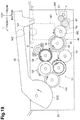
- FIG. 19 illustrates how the roller position changing mechanism behaves when the cover is started to be opened in the fourth illustrative embodiment according to one or more aspects of the disclosure.
- FIG. 20 illustrates how the roller position changing mechanism behaves when the cover arrives at the predetermined position in the fourth illustrative embodiment according to one or more aspects of the disclosure.
- FIG. 1 A first illustrative embodiment will be described with reference to appropriate ones of the accompanying drawings. Hereinafter, description will be made with reference to directions, top, bottom, front, and rear, as defined in FIG. 1 .
- the right and left of a thermal transfer apparatus 1 are defined as viewed from the front of the thermal transfer apparatus 1 .
- the thermal transfer apparatus 1 includes a housing 2 , a feed roller pair 3 , a discharge roller pair 4 , a motor 5 , a sensor 6 , a transfer device 140 , a roller position changing mechanism 180 , and a controller 200 .
- the housing 2 accommodates therein the feed roller pair 3 , the discharge roller pair 4 , the motor 5 , the sensor 6 , the transfer device 140 , the roller position changing mechanism 180 , and the controller 200 .
- the housing 2 includes a base housing 21 and a cover 22 .
- the base housing 21 has an opening 21 A (refer to FIG. 2 ) at its upper end.
- the cover 22 covers the opening 21 A of the base housing 21 .
- the cover 22 is pivotally supported by the base housing 21 , so that the cover 22 is movable between an open position at which the cover 22 uncovers the opening 21 A and a closed position at which the cover 22 covers the opening 21 A.
- the open position refers to a position at which the cover 22 is fully opened and cannot be further moved toward the front
- the closed position refers to a position at which the cover 22 is fully closed and the opening 21 A is not exposed.
- the cover 22 includes a plate portion 22 A and a sectorial portion 22 B.
- the plate portion 22 A is configured to, when the cover 22 is located at the closed position, cover the opening 21 A.
- the sectorial portion 22 B has an arc shaped portion when viewed in an axial direction of the cover 22 .
- the sectorial portion 22 B includes a gear 22 G.
- the gear 22 G may be a portion of the sectorial portion 22 B having teeth on a circumference of the sectorial portion 22 B.
- the thermal transfer apparatus 1 further includes a feed tray 23 and a discharge tray 24 at the base housing 21 .
- the feed tray 23 is configured to support one or more sheets S each having a toner image thereon.
- the feed tray 23 is disposed at the front of the base housing 21 .
- the discharge tray 24 is configured to support one or more sheets S on each of which a foil layer has been transferred by the transfer device 140 .
- the discharge tray 24 is disposed at the rear of the base housing 21 .
- the feed roller pair 3 is configured to feed and convey a sheet S toward the transfer device 140 from the feed tray 23 .
- the feed roller pair 3 is disposed between the feed tray 23 and the transfer device 140 in a sheet conveying direction.
- the feed roller pair 3 includes one roller, which is disposed at the cover 22 , and the other roller, which is disposed at the base housing 21 .
- the discharge roller pair 4 is configured to convey a sheet S that has passed the transfer device 140 toward the discharge tray 24 .
- the discharge roller pair 4 is disposed between the transfer device 140 and the discharge tray 24 in the sheet conveying direction.
- the discharge roller pair 4 includes one roller, which is disposed at the cover 22 , and the other roller, which is disposed at the base housing 21 .
- the motor 5 may be a drive source for supplying a driving force to the roller position changing mechanism 180 .
- the motor 5 is connected to the roller position changing mechanism 180 via gears (not illustrated).
- the sensor 6 is configured to detect a position of a cam 182 of the roller position changing mechanism 180 .
- the sensor 6 may be, for example, an optical sensor including a light emitter and a light receiver.
- the optical sensor may be a through-beam sensor configured to detect whether light emitted from the light emitter to the light receiver is blocked by the cam 182 .
- the optical sensor may be a reflective sensor configured to detect whether the light receiver has received light that was emitted from the light emitter and reflected off the cam 182 .
- the transfer device 140 is configured to transfer foil onto a toner image formed on a surface of a sheet S. More specifically, for example, the transfer device 140 places foil over a surface, having a toner image, of a sheet S and applies heat and pressure to the entire sheet S, i.e., both an image portion and a non-image portion of the sheet S, to transfer foil onto the toner image.
- the transfer device 140 is configured to transfer metallic foil onto a toner image.
- the transfer device 140 includes a film F, a supply reel 120 , a takeup reel 130 , a plurality of guide shafts 171 , a roller 141 , and a roller 142 .
- the roller 141 can be implemented as a heating roller
- the roller 142 can be implemented as a nip roller.
- the film F includes a tape-shaped base made of polymeric material, and at least both a releasable layer and a foil layer formed on the base.
- the film F has a width between or equal to 210 mm and 400 mm in an axial direction of the supply reel 120 and the takeup reel 130 and a length between or equal to 10 m and 300 m.
- the supply reel 120 holds such a new film F in a wound state before used.
- the film F wound around the supply reel 120 has a foil layer, no portion of which has been used or transferred to a toner image of a sheet S.
- the takeup reel 130 is disposed further to the rear than the supply reel 120 .
- the takeup reel 130 is configured to draw and wind the film F around the supply reel 120 . Therefore, during operation, the film F forms a web extending between the supply reel 120 and the takeup reel 130 , with the web extending between the roller 141 and roller 142 at a film location.
- Foil is a sheet of metal such as gold, silver, copper, or aluminum.
- the film F includes polymeric material mainly and has a thickness of between 5 and 250
- the film F may have a width longer than 400 mm in the axial direction of the supply reel 120 and the takeup reel 130 . That is, the film F includes a long narrow strip of material, such as a tape.
- the film F may include a plurality of layers made of different materials from a polymeric material used for the base.
- Two of the guide shafts 171 define a route that the film F moves from the supply reel 120 toward between the roller 141 and the roller 142 , and guide the film F along the route.
- the other two of the guide shafts 171 define a route that the film F moves from between the roller 141 and the roller 142 toward the takeup roller 130 , and guide the film F along the route.
- the guide shafts 171 hold the film F such that a portion of the film F extends along a direction in which a common tangent that is tangent to a circumferential surface of the roller 141 and a circumferential surface of the roller 142 (hereinafter, referred to as a “common tangent direction”) extends.
- the common tangent direction extends along the front-rear direction.
- the roller 141 and the roller 142 are disposed between the supply reel 120 and the takeup reel 130 in a direction from the supply reel 120 to the takeup reel 130 .
- the roller 141 is configured to heat a portion of the film F by heat applied to the roller 141 from a heating source (not illustrated).
- the roller 142 and the roller 141 nip a portion, which extends along the common tangent direction, of the film F therebetween. More specifically, for example, the roller 142 is disposed above the portion of the film F, and the pressure roller 143 is disposed below the portion of the film F. In other words, when the cover 22 is located at the closed position, at least a portion of the film F is located between the roller 141 and the roller 142 , such that, when roller 141 contacts the web of film F, roller 142 is positioned opposed to roller 141 and on an opposite side of film F.
- the roller 142 and the roller 141 nip the sheet S and a portion of the film F together.
- the roller 141 heats the toner image on the sheet S and the nipped portion of the film F having a foil layer to transfer a portion of the foil layer onto the toner image.
- the roller 142 is disposed at the cover 22 . Therefore, in response to opening of the cover 22 (refer to FIG. 2 ), the roller 142 becomes separated from the film F and roller 141 . As described above, while the one roller of each of the feed roller pair 3 and the discharge roller pair 4 is disposed at the cover 22 , and the other roller of each of the feed roller pair 3 and the discharge roller pair 3 is disposed at the base housing 21 .
- the one roller of each of the feed roller pair 3 and the discharge roller pair 4 becomes separated from the other roller of each of the feed roller pair 3 and the discharge roller pair 4 . That is, when the cover 22 is opened, those rollers are disengaged from each other so as not to provide a nip portion therebetween. Therefore, for example, in a case where a sheet S is jammed, a user may remove the sheet S readily by opening the cover 22 .
- the roller 141 is disposed at the base housing 21 via the roller position changing mechanism 180 .
- the roller position changing mechanism 180 is configured to move the roller 141 between a first position (refer to FIG. 1 ) that enables the roller 141 to contact a portion of the film F (e.g., a “film contact position”) and a second position (refer to FIG. 2 ) that enables the roller 141 to be spaced from the film F (e.g., a “retracted position”).
- the roller position changing mechanism 180 includes a support member 181 and the cam 182 .
- the support member 181 supports the roller 141 such that the roller 141 is rotatable.
- the cam 182 is for pressing the roller 141 toward the film F.
- the support member 181 is supported by the base housing 21 so as to be movable in the top-bottom direction.
- the cam 182 is disposed below the support member 181 and is configured to press the roller 141 toward the roller 142 via the support member 181 .
- the cam 182 is configured to move between a contacting position (refer to FIG. 1 ) that enables the roller 141 to contact the film F and a non-contacting position (refer to FIG. 2 ) that enables the roller 141 to be separated from the film F. More specifically, for example, the cam 182 is configured to rotate between the contacting position and the non-contacting position (e.g., first and second cam positions, respectively) by a driving force transmitted from the motor 5 or by a driving force transmitted from the cover 22 when the cover 22 is pivoted.
- the cam 182 has a sectorial shape when viewed in an axial direction of the cam 182 .
- the roller position changing mechanism 180 is configured to, when the cover 22 is located at the closed position, move the roller 141 between the first position and the second position by receiving a driving force from the motor 5 under appropriate control of the controller 200 .
- the roller position changing mechanism 180 is further configured to move the roller 141 to the second position in conjunction with opening of the cover 22 .
- the roller position changing mechanism 180 is further configured to retain the roller 141 at the second position during closing of the cover 22 .
- the roller position changing mechanism 180 further includes a cam gear Gc, a first transmission mechanism T 1 , and a second transmission mechanism T 2 , as well as the support member 181 and the cam 182 .
- the cam gear Gc is rotatable together with the cam 182 on the same axis as the cam 182 .
- the first transmission mechanism T 1 is configured to transmit a driving force from the motor 5 to the cam gear Gc.
- the second transmission mechanism T 2 is configured to transmit a driving force from the cover 22 to the cam gear Gc.
- the second transmission mechanism T 2 includes a gear train having a plurality of gears; example embodiments of such a gear train are discussed further below.
- gears disclosed therein have teeth on their entire circumference.
- the cover 22 has the axis at the different locations between FIG. 1 and FIG. 3 , the axis of the cover 22 does not change actually.
- the cam gear Gc is fixed to a shaft 182 A of the cam 182 and is rotatable together with the cam 182 .
- the shaft 182 A is rotatably supported by a frame 21 S of the base housing 21 .
- the cam 182 and the cam gear Gc are disposed on opposite sides of the frame 21 S. More specifically, for example, the cam 182 is disposed to the left of the frame 21 S and the cam gear Gc is disposed to the right of the frame 21 S. In other words, the frame 21 S is disposed between the cam 182 and the cam gear Gc in the axial direction of the cam 182 .
- the first transmission mechanism T 1 and the second transmission mechanism T 2 are disposed to the right of the frame 21 S. In other words, the frame 21 S is disposed between the first transmission mechanism T 1 and the cam 182 and between the second transmission mechanism T 2 and the cam 182 in the axial direction of the cam 182 .
- the first transmission mechanism T 1 includes a gear G 1 and an electromagnetic clutch EC.
- the gear G 1 meshes with both of a gear 5 G attached to the motor 5 and a gear EG attached to the electromagnetic clutch EC with interlocking teeth.
- the gear EG meshes with the gear G 1 and the cam gear Gc with interlocking teeth.
- the electromagnetic clutch EC is configured to switch between a driving force transmitting state (e.g., an “engaged state”), in which the electromagnetic clutch EC allows transmission of a driving force from the gear G 1 to the cam gear Gc and from the cam gear Gc to the gear G 1 , and a driving force blocking state (e.g., a “disengaged state”) in which the electromagnetic clutch EC blocks transmission of a driving force from the gear G 1 to the cam gear Gc and from the cam gear Gc to the gear G 1 when the cover 22 is closed.
- the controller 200 controls the state of the electromagnetic clutch EC and switches the state of the electromagnetic clutch EC between the driving force transmitting state and the driving force blocking state.
- the second transmission mechanism T 2 includes a partially toothless gear GN, a lock mechanism 7 , a transmission gear Gt, a one-way clutch C 1 , and a gear G 2 , G 3 .
- the partially toothless gear GN may be a double gear including a small-diameter gear N 1 and a large-diameter gear N 2 having a larger diameter than the small-diameter gear N 1 .
- the small-diameter gear N 1 meshes with the cam gear Gc with interlocking teeth.
- the large-diameter gear N 2 is configured to rotate together with the small-diameter gear N 1 .
- the large-diameter gear N 2 includes a toothed portion N 21 on a portion of its circumference and the toothed portion N 21 is meshable with the transmission gear Gt.
- the large-diameter gear N 2 further includes a toothless portion N 22 on the other portion of its circumference and the toothless portion N 22 does not mesh with the transmission gear Gt. Therefore, in a state where the toothless portion N 22 faces the transmission gear Gt, the large-diameter gear N 2 does not mesh with the transmission gear GT.
- the toothless portion N 22 is configured to, when the roller 141 is located at the second position at which the roller 141 is spaced from the film F, face the transmission gear Gt.
- the partially toothless gear GN further includes a protrusion N 3 that is engageable with the lock mechanism 7 .
- the protrusion N 3 is disposed between the small-diameter gear N 1 and the large-diameter gear N 2 of the partially toothless gear GN in an axial direction of the partially toothless gear GN.
- the protrusion N 3 protrudes from a toothless portion of an outer circumference of the partially toothless gear GN.
- the protrusion N 3 has a flat surface that is contactable with a hook 71 A of a lock lever 71 of the lock mechanism 7 .
- the flat surface of the protrusion N 3 extends from the small-diameter gear N 1 to the large-diameter gear N 2 in a diameter direction of the partially toothless gear GN.
- the lock mechanism 7 includes the lock lever 71 and a link member 72 .
- the lock lever 71 includes the hook 71 A and a protrusion 71 B.
- the hook 71 A is engageable with the protrusion N 3 .
- the protrusion 71 B is connected to the link member 72 .
- the hook 71 A has a flat surface that is surface-contactable with the flat surface of the protrusion N 3 . Therefore, the hook 71 A and the protrusion N 3 may be engaged with each other more reliably as compared with a case where the hook 71 A and the protrusion N 3 point-contact with each other. Consequently, such a reliable surface contact of the hook 71 A and the protrusion N 3 may stop rotation of the partially toothless gear GN reliably.
- the protrusion 71 B includes a protrusion that is engaged with an elongated hole of a first arm 72 A of the link member 72 .
- the lock lever 71 is swingably supported by the frame 21 S. More specifically, for example, the lock lever 71 is configured to swing between a locking position (refer to FIG. 6 ) that enables the hook 71 A to be located on a moving route of the protrusion N 3 , and an unlocking position (refer to FIG. 3 ) that enables the hook 71 A to be located out of the moving route of the protrusion N 3 .
- the lock lever 71 is urged toward the locking position by a spring (not illustrated).
- the link member 72 is swingably supported by the frame 21 S.
- the link member 72 includes the first arm 72 A and a second arm 72 B.
- the first arm 72 A extends from an axis of the link member 72 in one direction.
- the second arm 72 B extends from the axis of the link member 72 in another direction.
- the first arm 72 A is connected to the protrusion 71 B of the lock lever 71 via the elongated hole of the first arm 72 A.
- the second arm 72 B contacts a protrusion 22 A of the cover 22 .
- the cover 22 may receive, via the link member 72 , the urging force applied to the lock lever 71 by the spring.
- the protrusion 22 A of the cover 22 retains the link member 72 to locate the lock lever 71 at the unlocking position.
- the protrusion 22 A of the cover 22 is disengaged from the link member 72 and the link member 72 becomes free from the pressure of the protrusion 22 A. Therefore, the lock lever 71 swings to the locking position from the unlocking position by the urging force of the spring in conjunction with the opening of the cover 22 .
- the transmission gear Gt is configured to rotate in conjunction with opening of the cover 22 .
- the transmission gear Gt is meshable with the toothed portion N 21 of the partially toothless gear GN, and meshes with a first outer race C 12 of the one-way clutch C 1 with interlocking teeth.
- the one-way clutch C 1 has an engaged state and a disengaged state, and as such, is configured to transmit a rotating force in one direction only (e.g., when in the engaged state).
- the one-way clutch C 1 includes a first inner race C 11 and the first outer race C 12 .
- the first inner race C 11 has teeth on its entire circumference and meshes with the gear G 3 with interlocking teeth.
- the first outer race C 12 has teeth on its entire circumference and meshes with the transmission gear Gt with interlocking teeth.
- the first inner race C 11 is configured to, when rotating clockwise (in the engaged state), engage with the first outer race C 12 to rotate together with the first outer race C 12 .
- the one-way clutch C 1 allows transmission of a driving force from the cover 22 to the transmission gear Gt during opening of the cover 22 .
- the first inner race C 11 is further configured to, when rotating counterclockwise, rotate relative to the first outer race C 12 without engaging with the first outer race C 12 (e.g., in the disengaged state).
- the one-way clutch C 1 blocks transmission of a driving force from the cover 22 to the transmission gear Gt during closing of the cover 22 .
- the first outer race C 12 is configured to, when rotating clockwise, rotate relative to the first inner race C 11 without engaging with the first inner race C 11 .
- the one-way clutch C 1 blocks transmission of a driving force from the transmission gear Gt to the cover 22 .
- the gear G 2 may be a double gear including a large-diameter gear G 21 and a small-diameter gear G 22 having a smaller diameter than the large-diameter gear G 21 .
- the large-diameter gear G 21 is coaxial with the small-diameter gear G 22 and is rotatable together with the small-diameter gear G 22 .
- the larger-diameter gear G 21 meshes with a small-diameter gear G 31 of a gear G 3 .
- the small-diameter gear G 22 meshes with the gear 22 G of the cover 22 with interlocking teeth.
- a gear G 3 , a one-way clutch C 2 , and a damper D are disposed to the right of the frame S 21 .
- the gear G 3 may be a double gear including a small-diameter gear G 31 and a large-diameter gear G 32 having a larger diameter than the small-diameter gear G 31 .
- the small-diameter gear G 31 is coaxial with the large-diameter gear G 32 and is rotatable together with the large-diameter gear G 32 .
- the small-diameter gear G 31 meshes with the large-diameter gear G 21 of the gear G 2 with interlocking teeth.
- the larger-diameter gear G 32 meshes with an inner race C 21 of the one-way clutch C 2 with interlocking teeth, and also meshes with an inner race C 11 of one-way clutch C 1 with interlocking teeth.
- the one-way clutch C 2 has an engaged state and a disengaged state, and as such, is configured to transmit a rotating force in one direction only (e.g., in the engaged state).
- the one-way clutch C 2 includes the inner race C 21 and an outer race C 22 .
- the inner race C 21 has teeth on its entire circumference and meshes with the large-diameter gear G 32 of the gear G 3 with interlocking teeth.
- the outer race C 22 has teeth on its entire circumference and meshes with a gear DG attached to the damper D.
- the gear DG has teeth on its entire circumference.
- the inner race C 21 is configured to, when rotating counterclockwise, engage with the outer race C 22 to rotate together with the outer race C 22 (refer to FIG. 7 ).
- the one-way clutch C 2 operates in the engaged state, and allows transmission of a driving force of the cover 22 to the damper D during closing of the cover 22 .
- the inner race C 21 is further configured to, when rotating clockwise, rotate relative to the outer race C 22 without engaging with the outer race C 22 .
- the one-way clutch C 2 operates in the disengaged state, and blocks transmission of a driving force of the cover 22 to the damper D during opening of the cover 22 .
- the damper D may be a rotary damper and is configured to generate a brake force to control the moving speed of the cover 22 .
- a hydraulic damper which generates a brake using viscous resistance of oil contained therein, may be used as the damper D.
- the controller 200 is configured to, when executing a foil transfer control for transferring a foil layer onto a toner image of a sheet S, supply power to the electromagnetic clutch EC and the motor 5 for a predetermined time period to switch the position of the cam 182 appropriately between the contacting position (indicated by a dashed line in FIG. 4 ) and the non-contacting position (indicated by a double-dotted-and-dashed line). More specifically, for example, the controller 200 controls the cam 182 to be located at the non-contacting position from when a sheet S starts moving from the feed tray 23 until immediately before the sheet S enters a nip portion defined between the roller 142 and the film F.
- the controller 200 controls the cam 182 to be located at the contacting position when the sheet S enters the nip portion. This control may therefore enable the roller 141 to be kept separated from the film F until immediately before a sheet S enters the nip portion, and enable the roller 141 to contact film F when the sheet S enters the nip portion.
- the determination as to whether a sheet S has entered the nip portion may be made, for example, based on a detection result of a sheet sensor for detecting a sheet S or based on a time elapsed since the feed roller pair 3 started driving.
- the controller 200 controls a power source to start supplying power to the electromagnetic clutch EC and the motor 5 .
- the motor 5 starts rotating and the electromagnetic clutch EC enters the driving force transmitting state.
- a driving force of the motor 5 is allowed to be transmitted to the cam 182 .
- the controller 200 controls the power source to stop supplying power to at least one of the electromagnetic clutch EC and the motor 5 .
- the electromagnetic clutch EC enters the driving force blocking state (e.g., a disengaged state) or the motor 4 stops rotating.
- the driving force blocking state e.g., a disengaged state
- the controller 200 is connected to the sensor 6 via a bus so as to be capable of receiving a signal from the sensor 6 .
- the controller 200 is configured to, when the cover 22 is fully closed, determine, based on a signal outputted from the sensor 6 , whether the cam 182 is located at the non-contacting position (e.g., the first position). If the controller 200 determines that the cam 182 is not located at the non-contacting position, the controller 200 controls the electromagnetic clutch EC and the motor 5 to rotate the cam 182 to the non-contacting position.
- the controller 200 may determine, based on a signal outputted from a cover sensor, whether the cover 22 is located at the closed position. In such a case, the cover sensor may be configured to detect that the cover 22 is located at the closed position.
- the controller 200 drives the feed roller pair 3 (refer to FIG. 1 ) to feed and convey a sheet S toward the nip portion defined between the roller 142 and a portion of the film F without supplying power to the electromagnetic clutch EC and the motor 5 .
- the controller 200 controls the power source to start and keep supplying power to the electromagnetic clutch EC and the motor 5 for a predetermined time period.
- the motor 5 starts rotating clockwise in FIG. 4 and a driving force of the motor 5 is transmitted to the cam gear Gc for the predetermined time period via the gear G 1 and the electromagnetic clutch EC to rotate the cam 182 counterclockwise by 180 degrees in FIG. 4 . That is, the cam 182 rotates from the non-contacting position (e.g., the second position) to the contacting position (e.g., the first position) and moves the support member 181 upward to move the roller 141 from the second position to the first position. Consequently, an appropriate degree of nip pressure may be surely generated at the nip portion defined between a portion of the film F and the roller 142 , thereby achieving a preferable foil transfer.
- the partially toothless gear GN, the transmission gear Gt, and the first outer race C 12 of the one-way clutch C 1 also rotate.
- the first outer race C 12 rotates clockwise in FIG. 4 , and therefore, the first outer race C 12 idly rotates relative to the first inner race C 11 . That is, the first inner race C 11 does not rotate and the driving force of the motor 5 is thus not transmitted to the cover 22 .
- the motor 5 is driven in a state where the cover 22 is located at the closed position, the cover 22 does not open and instead stays at the closed position.
- some components, such as gears are filled with dots. Those components remains stationary under respective situations shown in the respective drawings although other components are rotated or driven.
- the controller 200 controls the power source to start supplying power to the electromagnetic clutch EC and the motor 5 for the predetermined time period to rotate the cam 182 counterclockwise by 180 degrees in FIG. 4 . That is, the cam 182 rotates from the contacting position (e.g., the first position) to the non-contacting position (e.g., the second position). Therefore, the support member 181 moves downward gradually by its own weight to move the roller 141 from the first position to the second position. Accordingly, until the next sheet S arrives at the nip portion, the roller 141 may be kept separated from the film F, thereby avoiding unnecessary or excessive heating of the film F.
- the second transmission mechanism T 2 configured to transmit a driving force of the cover 22 to the cam 182 is provided. Therefore, although a driving force of the motor 5 is not allowed to be transmitted to the cam 182 , the cam 182 may be rotated in conjunction with opening of the cover 22 . Thus, the user enables the roller 141 to move from the first position (e.g., a film contact position) to the second position (e.g., a retracted position) although the driving force of the motor 5 is not allowed to be transmitted to the cam 182 . In other words, although the driving force of the motor 5 is not allowed to be transmitted to the cam 182 , the thermal transfer apparatus 1 enables the roller 141 to move from the first position to the second position.
- the first position e.g., a film contact position
- the second position e.g., a retracted position
- a driving force of the cover 22 is transmitted to the cam gear Gc via the gear 22 G, the gear G 2 , the gear G 3 , the one-way clutch C 1 , the transmission gear Gt, and the partially toothless gear GN.
- the cam 182 starts rotating toward the non-contacting position from the contacting position.
- the cam 182 when the cover 22 arrives at a predetermined position (e.g., a position indicated by a solid line), the cam 182 is located at the non-contacting position by rotation. In such a state, the toothless portion N 22 of the partially toothless gear GN faces the transmission gear Gt and thus the partially toothless gear GN does not mesh with the transmission gear Gt. Therefore, the driving force is not allowed to be transmitted from the transmission gear Gt to the partially toothless gear GN. Thus, the cam 182 is retained at the non-contacting position and the roller 141 is retained at the second position that enables the roller 141 to be separated from the film F (e.g., at the retracted position). When the toothless portion N 22 of the partially toothless gear GN faces the transmission gear Gt, the lock lever 71 engages with the protrusion N 3 . Therefore, the rotation of the partially toothless gear GN is locked by the lock lever 71 .
- a predetermined position e.g., a position indicated by a solid line
- the roller 141 is retained at the second position because the driving force is not allowed to be transmitted from the transmission gear Gt to the partially toothless gear GN. Accordingly, if the power source is forcedly turned off during foil transfer due to an accidental opening of the cover 22 by the user, the roller 141 may be separated from the film F by the driving force of the cover 22 , thereby avoiding unnecessary or excessive heating of the film F.
- the driving force of the cover 22 is transmitted to the first inner race C 11 of the one-way clutch C 1 via the gear 22 G, the gear G 2 , and the gear G 3 .
- the first inner race C 11 rotates counterclockwise in FIG. 7 , and therefore, the first inner race C 11 idly rotates relative to the first outer race C 12 . That is, the first outer race C 12 does not rotate together with the first inner race C 11 , as the one-way clutch C 1 is in a disengaged state.
- the driving force of the cover 22 is not transmitted to the cam 182 and the roller 141 is retained at the second position.
- the damper D may lessen an impact caused when the cover 22 arrives at the closed position.
- the transmission route of the driving force of the cover 22 generated during closing of the cover 22 does not change until the cover 22 arrives at the closed position. Therefore, the roller 141 may be retained at the second position during closing of the cover 22 until the cover 22 arrives at the closed position. Accordingly, if the user fully opens the cover 22 accidentally during foil transfer and then fully closes the cover 22 immediately afterwards, the roller 141 remains separated from the film F, thereby avoiding unnecessary or excessive heating of the film F.
- the protrusion 22 A of the cover 22 contacts and presses the link member 72 downward to swing the lock lever 71 to the locking position from the unlocking position. Therefore, when the cover 22 is located at the closed position, the hook 71 A of the lock lever 71 is disengaged from the protrusion N 3 of the partially toothless gear GN. Consequently, during the next foil transfer, the cam 182 may be rotated reliably by a driving force of the motor 5 . Further, the damper D may lessen an impact caused when the protrusion 22 A contacts the link member 72 . Therefore, damage to the protrusion 22 A and/or the link member 72 may be reduced.
- the cam 182 may stop rotating at a position different from the contacting position and the non-contacting position. More specifically, for example, as the cover 22 is opened to a position of FIG. 5 , the cam 182 slightly rotates toward the non-contacting position from the contacting position. Then, if the cover 22 moves toward the closed position from the position of FIG. 5 , the first switching member C 1 blocks transmission of the driving force of the cover 22 to the cam 182 . Therefore, the cam 182 is retained at the position slightly shifted from the contacting position. In such a case, the roller 141 may remain contacting the film F.
- the controller 200 detects the position of the cam 182 using the sensor 6 . Based on the detection result, the controller 200 causes the cam 182 to rotate to the non-contacting position, thereby avoiding unnecessary or excessive heating of the film F.
- the roller 141 may be kept separated from the film F by the driving force of the motor 5 , thereby avoiding unnecessary or excessive heating of the film F.
- the roller 141 is configured to move away from the film F in conjunction with opening of the cover 22 . Therefore, in a case where the user opens the cover 22 accidentally during foil transfer or in a case where the user clears a jam, the roller 141 is separated from the film F and unnecessary or excessive heating of the film F may be avoided.
- the roller 141 is further configured to be retained at the second position during closing of the cover 22 . Therefore, if the temperature of the roller 141 is still relatively high when the cover 22 is fully closed, the roller 141 does not contact the film F and unnecessary or excessive heating of the film F may be avoided.
- one-way clutches are used as the one-way clutch C 1 and the one-way clutch C 2 . Therefore, the roller position changing mechanism 181 may be smaller in size as compared with a case where the one-way clutch C 1 and the one-way clutch C 2 each have another configuration.
- the driving force of the cover 22 generated during closing of the cover 22 is transmitted to the damper D. Therefore, the closing speed of the cover 22 may be reduced.
- the thermal transfer apparatus 1 includes a roller position changing mechanism 280 as a substitute for the roller position changing mechanism 180 .
- the roller position changing mechanism 280 includes a rack gear C 3 different from the one-way clutch C 1 of the first illustrative embodiment.
- the rack gear C 3 is movable linearly.
- the rack gear C 3 is supported by the base housing 21 so as to be movable in the front-rear direction.
- the rack gear C 3 includes a toothed portion C 31 , a toothed portion C 32 , and a toothless portion C 33 .
- the toothed portion C 31 meshes with the gear G 2 with interlocking teeth.
- the toothed portion C 32 is meshable with the toothed portion N 21 of the partially toothless gear GN.
- the toothless portion C 33 does not mesh with any portion of the partially toothless gear GN when the toothless portion C 33 faces the partially toothless gear GN.
- the toothed portion C 32 corresponds to a transmission gear.
- the toothless portion C 33 is disposed between the toothed portion C 31 and the toothed portion C 32 in the front-rear direction. In a state where the cover 22 is located at the closed position, the toothless portion C 33 faces the toothed portion N 21 of the partially toothless gear GN in the top-bottom direction, i.e., in a direction orthogonal to a direction in which the rack gear C 3 moves.
- the toothed portion C 31 meshes with the gear G 2 with interlocking teeth wherever the cover 22 is located between the closed position and the open position.
- the toothed portion C 32 does not mesh with the toothed portion N 21 of the partially toothless gear GN.
- the toothed portion C 32 meshes with the toothed portion N 21 of the partially toothless gear GN.
- the toothed portion C 32 is disposed at a different position from the cam 182 and the cam gear 182 in the axial direction of the cam 182 .
- the toothless portion C 33 of the rack gear C 3 faces the partially toothless gear GN and the rack gear C 3 does not mesh with the partially toothless gear GN.
- transmission of a driving force of the motor 5 from the partially toothless gear GN to the rack gear C 3 is not allowed. Therefore, as in the case of the first illustrative embodiment, the position of the cam 182 may be changed by the driving force of the motor 5 at an appropriate timing.
- a third illustrative embodiment will be described with reference to appropriate ones of the accompanying drawings.
- changes are applied to the roller position changing mechanism 180 of the first illustrative embodiment. Therefore, an explanation will be given mainly for the components different from the first illustrative embodiment, and an explanation will be omitted for the common components by assigning the same reference numerals thereto.
- the thermal transfer apparatus 1 includes a roller position changing mechanism 380 as a substitute for the roller position changing mechanism 180 .
- the roller position changing mechanism 380 includes a switching mechanism C 4 different from the one-way clutch C 1 of the first illustrative embodiment, and a switching mechanism C 5 different from the one-way clutch C 2 of the first illustrative embodiment.
- the switching mechanism C 4 includes a base gear C 41 and a pendulum gear C 42 .
- the base gear C 41 is configured to rotate in conjunction with opening and closing of the cover 22 .
- the base gear C 41 meshes with the gear G 2 with interlocking teeth.
- the pendulum gear C 42 is movable between a first meshing position (e.g., a position indicated by a solid line in FIG. 13 ) and a first disengaging position (e.g., a position in FIG. 12 ) while meshing with the base gear C 41 .
- a first meshing position e.g., a position indicated by a solid line in FIG. 13
- a first disengaging position e.g., a position in FIG. 12
- the pendulum gear C 42 meshes with the transmission gear Gt.
- the pendulum gear C 42 does not mesh with the transmission gear Gt.
- the cover 22 is located at the closed position, the pendulum gear C 42 is located at the first disengaging position.
- the pendulum gear C 42 moves from the first disengaging position to the first meshing position. As the cover 22 moves from the open position to the closed position, the pendulum gear C 42 moves from the first meshing position to the first disengaging position.
- the base housing 21 further includes an urging member SP that urges the pendulum gear C 42 in a direction away from the transmission gear Gt.
- the urging member SP may be a torsion spring.
- the urging member SP has one end engaged with a shaft of the pendulum gear C 42 and the other end engaged with a spring retaining portion 21 B of the base housing 21 .
- the switching mechanism C 5 includes the base gear C 41 and a pendulum gear C 52 . That is, in the third illustrative embodiment, the base gear C 41 is commonly used as the base gear of the switching mechanism C 4 and the base gear of the switching mechanism C 5 .
- the pendulum gear C 52 is movable between a second meshing position (e.g., a position in FIG. 12 ) and a second disengaging position (e.g., a position indicated by a solid line in FIG. 13 ) while meshing with the base gear C 41 .
- a second meshing position e.g., a position in FIG. 12
- a second disengaging position e.g., a position indicated by a solid line in FIG. 13
- the pendulum gear C 52 meshes with the damper D.
- the pendulum gear C 52 does not mesh with the damper D.
- the cover 22 is located at the closed position, the pendulum gear C 52 is located at the second meshing position.
- the pendulum gear C 52 moves from the second meshing position to the second disengaging position. As the cover 22 moves from the open position to the closed position, the pendulum gear C 52 moves from the second disengaging position to the second meshing position.
- the pendulum gear C 42 does not engage with the transmission gear Gt.
- transmission of a driving force of the motor 5 from the transmission gear Gt to the switching mechanism C 4 is not allowed. Therefore, as in the case of the first illustrative embodiment, the position of the cam 182 may be changed by the driving force of the motor 5 at an appropriate timing.
- the transmission of the driving force of the cover 22 from the transmission gear Gt to the partially toothless gear GN is blocked.
- the cam 182 stops rotating and stays at the non-contacting position.
- the same effects as the effects achieved in the first illustrative embodiment may be achieved.
- the pendulum gear C 42 is used in the switching mechanism C 4 . Therefore, manufacturing costs may be further reduced as compared with the second illustrative embodiment in which a rack gear is used.
- the pendulum gear C 42 and the pendulum gear C 52 are used in the switching mechanism C 4 and the switching mechanism C 5 , respectively. Therefore, manufacturing costs may be reduced as compared with the first illustrative embodiment in which the one-way clutch C 1 and the one-way clutch C 2 are used.
- the urging member SP that urges the pendulum gear C 42 in the direction away from the transmission gear Gt is provided. Therefore, when the cover 22 is located at the closed position, the pendulum gear C 42 may be disengaged from the transmission gear Gt reliably.
- a fourth illustrative embodiment will be described with reference to appropriate ones of the accompanying drawings.
- changes are applied to the roller position changing mechanism 180 of the first illustrative embodiment. Therefore, an explanation will be given mainly for the components different from the first illustrative embodiment, and an explanation will be omitted for the common components by assigning the same reference numerals thereto.
- the thermal transfer apparatus 1 includes a roller position changing mechanism 480 as a substitute for the roller position changing mechanism 180 .
- the roller position changing mechanism 480 includes a planetary gear mechanism 80 as a substitute for the partially toothless gear GN of the first illustrative embodiment.
- the planetary gear mechanism 80 includes a sun gear 81 , a plurality of planet gears 82 , a ring gear 83 , and a carrier 84 .
- the sun gear 81 may be a double gear including a large-diameter gear 81 A and a small-diameter gear 81 B having a smaller diameter than the large-diameter gear 81 A.
- the large-diameter gear 81 A meshes with the transmission gear Gt with interlocking teeth.
- the small-diameter gear 81 B meshes with each of the planet gears G 21 with interlocking teeth.
- the small-diameter gear 81 B is rotatable together with the large-diameter gear 81 A.
- the planet gears 82 are disposed around the small-diameter gear 81 B of the sun gear 81 .
- Each of the planet gears 82 meshes with the small-diameter gear 81 B and internal teeth 83 A of the ring gear 83 with interlocking teeth.
- the ring gear 83 has an outside diameter smaller than the diameter of the large-diameter gear 81 A of the sun gear 81 .
- the ring gear 82 has the internal teeth 83 A on its entire inner circumference.
- the carrier 84 may be a hollow cylindrical member having an outside diameter smaller than the outside diameter of the ring gear 83 .
- the carrier 84 supports a shaft of each of the planet gears 82 at its one end such that the planet gears 82 are rotatable.
- the carrier 84 has teeth on a portion of its outer circumference. The teeth are provided on an entire circumference of the portion of the carrier 84 so as to mesh with the cam gear Gc with interlocking teeth.
- a driving force of the cover 22 is allowed to be transmitted to the cam gear Gc via the transmission gear Gt, the sun gear 81 , the planet gears 82 , and the carrier 84 .
- the planet gears 82 rotate along the internal circumference of the locked ring gear 83 . That is, each of the planet gears 82 rotates around the axis of the sun gear 81 while rotating on its own axis.
- the carrier 84 rotates and the driving force of the cover 22 is transmitted from the carrier 84 to the cam gear Gc.
- the thermal transfer apparatus 1 further includes a lock mechanism 90 at the base housing 21 so as to be pivotable.
- the lock mechanism 90 includes a first lock arm 91 , a second lock arm 92 , and a spring 93 .
- the first lock arm 91 is configured to lock the ring gear 83 .
- the second lock arm 92 is configured to lock the carrier 84 .
- the spring 93 urges the second lock arm 92 toward the carrier 84 .
- the first lock arm 91 is pivotable relative to the base housing 21 .
- the first lock arm 91 includes one end portion that is supported by the base housing 21 and the other end portion that includes a hook 91 A.
- the ring gear 83 has protrusions 83 B (e.g., teeth) on an entire outer circumference of the ring gear 83 with equal pitches.
- the hook 91 A of the first lock arm 91 is engageable with one of the protrusions 83 B of the ring gear 83 .
- the first lock arm 91 and the second lock arm 92 are held by the same shaft so as to extend therefrom perpendicular to each other.
- the second lock arm 92 is pivotable together with the first lock arm 91 relative to the base housing 21 on the shaft commonly used as the shaft of the first lock arm 91 .
- the second lock arm 92 includes one end portion that is fixed to the one end portion of the first lock arm 91 and that is pivotally supported by the base housing 21 .
- the second lock arm 92 further includes the other end portion that includes a hook 92 A.
- the hook 92 A is engageable with a recessed portion 84 B defined in the outer circumference of the carrier 84 .
- the second lock arm 92 is located at a different position from the first lock arm 91 in an axial direction of the sum gear 81 .
- the spring 93 is disposed between a spring retaining portion 21 C and the second lock arm 92 .
- the spring retaining portion 21 C is disposed at the base housing 21 .
- the cover 22 further includes an arm retainer 22 B that is contactable to the first lock arm 91 .
- the arm retainer 22 B of the cover 22 contacts and retains the first lock arm 91 at a position where the first lock arm 91 engages with one of the protrusions 83 B of the ring arm 83 (refer to FIG. 17A ), thereby locking the ring gear 83 . Therefore, in the state where the cover 22 is located at the closed position, a driving force is allowed to be transmitted from the transmission gear Gt to the cam gear Gc and from the cam gear Gc to the transmission gear Gt (refer to FIG. 18A ).
- the second lock arm 92 is retained at a position where the second lock arm 92 is spaced from the recessed portion 84 B (refer to FIG. 17A ).
- the spring 93 is compressed between the second lock arm 92 and the spring retaining portion 21 C.
- the second lock arm 92 starts pivoting toward the carrier 84 by an urging force of the spring 93 , thereby engaging with the recessed portion 84 B (refer to FIG. 17B ).
- the ring gear 84 becomes locked. Therefore, in the state where the cover 22 is located at the predetermined position, a driving force is not allowed to be transmitted from the transmission gear Gt to the cam gear Gc (refer to FIG. 18B ). In such a state, the first lock arm 91 is retained at a position there the first lock arm 91 is spaced from the protrusions 83 B.
- the arm retainer 22 B of the cover 22 retains the first lock arm 91 such that the first lock arm 91 engages with one of the protrusions 83 B of the ring gear 83 .
- the cam 182 is rotated by a driving force of the cover 22 .
- the cam 182 is located at the non-contacting position and the arm retainer 22 B disengages from the first lock arm 91 .
- the transmission of the driving force of the cover 22 to the cam 182 is blocked, thereby stopping rotation of the cam 182 and retaining the cam 182 at the non-contacting position.
- the ring gear 83 is locked by the lock mechanism 90 . Therefore, as illustrated in FIG. 16B , while transmission of a driving force of the motor 5 to the transmission gear Gt from the cam gear Gc via the planetary gear mechanism 80 is allowed, transmission of the driving force of the motor 5 to the cover 22 is blocked by the one-way clutch C 1 as in the case of the first illustrative embodiment.
- the position of the cam 182 may be changed at an appropriate timing by application of the driving force of the motor 5 .
- a sheet S may be, for example, plain paper, thick paper, or overhead projector sheet.
- the film F might not necessarily include a foil layer.
- a film may include a coloring layer, e.g., a woodgrain layer, as a substitute fora foil layer.
- a film may include an adhesive layer capable of adhering to toner and a releasable layer disposed between the adhesive layer and a base only.
- the cam 182 is used for pressing the roller 141 toward the film F.
- an elastic member e.g., a spring
- a cam may be used for separating the heat roller from the film by urging the heat roller against an urging force of the elastic member.
- the base gear C 41 is commonly used as the base gear of the switching mechanism C 4 and the base gear of the switching mechanism C 5 .
- a switching mechanism C 4 may include a first base gear and a first pendulum gear
- a switching mechanism C 5 may include another base gear, e.g., a second base gear, and a second pendulum gear.
- the urging member SP is a torsion spring.
- the urging member SP may be, for example, a coil compression spring, a coil tension spring, a leaf spring, or a wire spring.
Landscapes
- Physics & Mathematics (AREA)
- General Physics & Mathematics (AREA)
- Engineering & Computer Science (AREA)
- Mechanical Engineering (AREA)
- Electrostatic Charge, Transfer And Separation In Electrography (AREA)
Abstract
Description
Claims (21)
Applications Claiming Priority (4)
| Application Number | Priority Date | Filing Date | Title |
|---|---|---|---|
| JP2017184393 | 2017-09-26 | ||
| JP2017-184393 | 2017-09-26 | ||
| JP2018-175155 | 2018-09-19 | ||
| JP2018175155A JP7151310B2 (en) | 2017-09-26 | 2018-09-19 | film transfer device |
Publications (2)
| Publication Number | Publication Date |
|---|---|
| US20190094767A1 US20190094767A1 (en) | 2019-03-28 |
| US10627752B2 true US10627752B2 (en) | 2020-04-21 |
Family
ID=65808990
Family Applications (1)
| Application Number | Title | Priority Date | Filing Date |
|---|---|---|---|
| US16/139,381 Active US10627752B2 (en) | 2017-09-26 | 2018-09-24 | Thermal transfer apparatus |
Country Status (1)
| Country | Link |
|---|---|
| US (1) | US10627752B2 (en) |
Families Citing this family (5)
| Publication number | Priority date | Publication date | Assignee | Title |
|---|---|---|---|---|
| WO2020158004A1 (en) * | 2019-01-29 | 2020-08-06 | ブラザー工業株式会社 | Layer transfer device |
| JP7218591B2 (en) * | 2019-01-30 | 2023-02-07 | ブラザー工業株式会社 | Layer transfer device |
| JP7468083B2 (en) * | 2020-04-01 | 2024-04-16 | ブラザー工業株式会社 | Foil transfer device |
| JP7655102B2 (en) * | 2021-06-14 | 2025-04-02 | ブラザー工業株式会社 | Foil transfer device |
| JP7666163B2 (en) * | 2021-06-24 | 2025-04-22 | ブラザー工業株式会社 | Cartridges and holders for foil transfer devices |
Citations (5)
| Publication number | Priority date | Publication date | Assignee | Title |
|---|---|---|---|---|
| US5045887A (en) * | 1989-08-09 | 1991-09-03 | Minolta Camera Kabushiki Kaisha | Fixing device with a selectively movable cover |
| US5179415A (en) * | 1990-06-20 | 1993-01-12 | Fujitsu Limited | Electro-photographic printing apparatus comprising a toner fixing unit |
| JPH068571A (en) | 1992-06-29 | 1994-01-18 | Mitsubishi Electric Corp | Printer |
| JP2002120960A (en) | 2000-10-18 | 2002-04-23 | Canon Inc | Film feeder and image forming apparatus having the same |
| US20050271863A1 (en) * | 2004-05-10 | 2005-12-08 | Dai Nippon Printing Co., Ltd. | Protective layer transfer film, intermediate recording medium and printed matter |
-
2018
- 2018-09-24 US US16/139,381 patent/US10627752B2/en active Active
Patent Citations (5)
| Publication number | Priority date | Publication date | Assignee | Title |
|---|---|---|---|---|
| US5045887A (en) * | 1989-08-09 | 1991-09-03 | Minolta Camera Kabushiki Kaisha | Fixing device with a selectively movable cover |
| US5179415A (en) * | 1990-06-20 | 1993-01-12 | Fujitsu Limited | Electro-photographic printing apparatus comprising a toner fixing unit |
| JPH068571A (en) | 1992-06-29 | 1994-01-18 | Mitsubishi Electric Corp | Printer |
| JP2002120960A (en) | 2000-10-18 | 2002-04-23 | Canon Inc | Film feeder and image forming apparatus having the same |
| US20050271863A1 (en) * | 2004-05-10 | 2005-12-08 | Dai Nippon Printing Co., Ltd. | Protective layer transfer film, intermediate recording medium and printed matter |
Also Published As
| Publication number | Publication date |
|---|---|
| US20190094767A1 (en) | 2019-03-28 |
Similar Documents
| Publication | Publication Date | Title |
|---|---|---|
| US10627752B2 (en) | Thermal transfer apparatus | |
| US5730536A (en) | Tape printer having platen moving mechanism and mechanism for interlocking platen and tape feed roller with movement of cover | |
| US5882002A (en) | Paper feeding device | |
| US5758840A (en) | Paper magazine | |
| CN101096153A (en) | printing device | |
| JP5605759B2 (en) | Roll paper drive device and image forming apparatus | |
| JPH0431315B2 (en) | ||
| JP5104537B2 (en) | Sealing device and envelope sealing method | |
| JPH05301405A (en) | Mechanism for preventing carbon ribbon from relaxing in printing apparatus | |
| US8219012B2 (en) | Retraction mechanism for a toner image transfer apparatus | |
| JP7151310B2 (en) | film transfer device | |
| JP3825155B2 (en) | Stencil printing machine | |
| JP7124527B2 (en) | image forming device | |
| JP6184279B2 (en) | Driving force switching mechanism and image forming apparatus | |
| JP2843713B2 (en) | Paper reversing mechanism | |
| US7882781B2 (en) | Duplex printing apparatus having control unit to control printing speed | |
| JP3369004B2 (en) | Color thermal printer | |
| JP7666163B2 (en) | Cartridges and holders for foil transfer devices | |
| JP3867759B2 (en) | Roll paper identification device | |
| JPH072210Y2 (en) | Paper feeder for printer | |
| JPS6230430B2 (en) | ||
| JP2702269B2 (en) | Recording paper conveying method and apparatus | |
| JP2000108472A (en) | Printing equipment | |
| KR100194369B1 (en) | Paper Magazine | |
| JP2672393B2 (en) | Recording paper storage cassette |
Legal Events
| Date | Code | Title | Description |
|---|---|---|---|
| AS | Assignment |
Owner name: BROTHER KOGYO KABUSHIKI KAISHA, JAPAN Free format text: ASSIGNMENT OF ASSIGNORS INTEREST;ASSIGNOR:SAKAI, RYOSUKE;REEL/FRAME:046949/0587 Effective date: 20180919 |
|
| FEPP | Fee payment procedure |
Free format text: ENTITY STATUS SET TO UNDISCOUNTED (ORIGINAL EVENT CODE: BIG.); ENTITY STATUS OF PATENT OWNER: LARGE ENTITY |
|
| STPP | Information on status: patent application and granting procedure in general |
Free format text: DOCKETED NEW CASE - READY FOR EXAMINATION |
|
| STPP | Information on status: patent application and granting procedure in general |
Free format text: NON FINAL ACTION MAILED |
|
| STPP | Information on status: patent application and granting procedure in general |
Free format text: RESPONSE TO NON-FINAL OFFICE ACTION ENTERED AND FORWARDED TO EXAMINER |
|
| STPP | Information on status: patent application and granting procedure in general |
Free format text: NOTICE OF ALLOWANCE MAILED -- APPLICATION RECEIVED IN OFFICE OF PUBLICATIONS |
|
| STPP | Information on status: patent application and granting procedure in general |
Free format text: PUBLICATIONS -- ISSUE FEE PAYMENT RECEIVED |
|
| STCF | Information on status: patent grant |
Free format text: PATENTED CASE |
|
| MAFP | Maintenance fee payment |
Free format text: PAYMENT OF MAINTENANCE FEE, 4TH YEAR, LARGE ENTITY (ORIGINAL EVENT CODE: M1551); ENTITY STATUS OF PATENT OWNER: LARGE ENTITY Year of fee payment: 4 |