US10627171B2 - Submersed heat exchanger - Google Patents
Submersed heat exchanger Download PDFInfo
- Publication number
- US10627171B2 US10627171B2 US14/694,056 US201514694056A US10627171B2 US 10627171 B2 US10627171 B2 US 10627171B2 US 201514694056 A US201514694056 A US 201514694056A US 10627171 B2 US10627171 B2 US 10627171B2
- Authority
- US
- United States
- Prior art keywords
- coil
- fluid
- heat exchanger
- temperature
- flow
- Prior art date
- Legal status (The legal status is an assumption and is not a legal conclusion. Google has not performed a legal analysis and makes no representation as to the accuracy of the status listed.)
- Active
Links
- 239000012530 fluid Substances 0.000 claims abstract description 146
- 229930195733 hydrocarbon Natural products 0.000 claims abstract description 26
- 150000002430 hydrocarbons Chemical class 0.000 claims abstract description 26
- 239000004215 Carbon black (E152) Substances 0.000 claims abstract description 24
- 238000012546 transfer Methods 0.000 claims description 37
- 238000012423 maintenance Methods 0.000 claims description 9
- 239000013535 sea water Substances 0.000 claims description 7
- XLYOFNOQVPJJNP-UHFFFAOYSA-N water Substances O XLYOFNOQVPJJNP-UHFFFAOYSA-N 0.000 claims description 6
- 239000002519 antifouling agent Substances 0.000 claims description 4
- 238000000034 method Methods 0.000 abstract description 18
- 238000013461 design Methods 0.000 description 16
- 238000004519 manufacturing process Methods 0.000 description 14
- 238000001816 cooling Methods 0.000 description 8
- 238000013459 approach Methods 0.000 description 4
- 238000004891 communication Methods 0.000 description 3
- 239000002826 coolant Substances 0.000 description 3
- 230000007613 environmental effect Effects 0.000 description 3
- 239000000463 material Substances 0.000 description 3
- 229910001369 Brass Inorganic materials 0.000 description 2
- 229910000975 Carbon steel Inorganic materials 0.000 description 2
- 230000005540 biological transmission Effects 0.000 description 2
- 239000010951 brass Substances 0.000 description 2
- 239000010962 carbon steel Substances 0.000 description 2
- 230000003628 erosive effect Effects 0.000 description 2
- 229910052751 metal Inorganic materials 0.000 description 2
- 239000002184 metal Substances 0.000 description 2
- 238000012545 processing Methods 0.000 description 2
- 239000003643 water by type Substances 0.000 description 2
- 241001317177 Glossostigma diandrum Species 0.000 description 1
- 229910000831 Steel Inorganic materials 0.000 description 1
- 230000003213 activating effect Effects 0.000 description 1
- 239000003570 air Substances 0.000 description 1
- WYTGDNHDOZPMIW-RCBQFDQVSA-N alstonine Natural products C1=CC2=C3C=CC=CC3=NC2=C2N1C[C@H]1[C@H](C)OC=C(C(=O)OC)[C@H]1C2 WYTGDNHDOZPMIW-RCBQFDQVSA-N 0.000 description 1
- 239000011449 brick Substances 0.000 description 1
- 238000004140 cleaning Methods 0.000 description 1
- 230000008602 contraction Effects 0.000 description 1
- 230000001419 dependent effect Effects 0.000 description 1
- 238000005553 drilling Methods 0.000 description 1
- -1 e.g. Substances 0.000 description 1
- 230000000694 effects Effects 0.000 description 1
- 238000010348 incorporation Methods 0.000 description 1
- 229910052500 inorganic mineral Inorganic materials 0.000 description 1
- 238000009434 installation Methods 0.000 description 1
- 230000002452 interceptive effect Effects 0.000 description 1
- QSHDDOUJBYECFT-UHFFFAOYSA-N mercury Chemical compound [Hg] QSHDDOUJBYECFT-UHFFFAOYSA-N 0.000 description 1
- 229910052753 mercury Inorganic materials 0.000 description 1
- 229910001092 metal group alloy Inorganic materials 0.000 description 1
- 150000002739 metals Chemical class 0.000 description 1
- 239000011707 mineral Substances 0.000 description 1
- 239000000203 mixture Substances 0.000 description 1
- 238000007747 plating Methods 0.000 description 1
- 239000011435 rock Substances 0.000 description 1
- 239000004576 sand Substances 0.000 description 1
- 238000007789 sealing Methods 0.000 description 1
- 239000007787 solid Substances 0.000 description 1
- 239000010959 steel Substances 0.000 description 1
- 238000010998 test method Methods 0.000 description 1
Images


Classifications
-
- E—FIXED CONSTRUCTIONS
- E21—EARTH OR ROCK DRILLING; MINING
- E21B—EARTH OR ROCK DRILLING; OBTAINING OIL, GAS, WATER, SOLUBLE OR MELTABLE MATERIALS OR A SLURRY OF MINERALS FROM WELLS
- E21B36/00—Heating, cooling or insulating arrangements for boreholes or wells, e.g. for use in permafrost zones
- E21B36/001—Cooling arrangements
-
- F—MECHANICAL ENGINEERING; LIGHTING; HEATING; WEAPONS; BLASTING
- F28—HEAT EXCHANGE IN GENERAL
- F28F—DETAILS OF HEAT-EXCHANGE AND HEAT-TRANSFER APPARATUS, OF GENERAL APPLICATION
- F28F27/00—Control arrangements or safety devices specially adapted for heat-exchange or heat-transfer apparatus
-
- E—FIXED CONSTRUCTIONS
- E21—EARTH OR ROCK DRILLING; MINING
- E21B—EARTH OR ROCK DRILLING; OBTAINING OIL, GAS, WATER, SOLUBLE OR MELTABLE MATERIALS OR A SLURRY OF MINERALS FROM WELLS
- E21B43/00—Methods or apparatus for obtaining oil, gas, water, soluble or meltable materials or a slurry of minerals from wells
- E21B43/01—Methods or apparatus for obtaining oil, gas, water, soluble or meltable materials or a slurry of minerals from wells specially adapted for obtaining from underwater installations
-
- F—MECHANICAL ENGINEERING; LIGHTING; HEATING; WEAPONS; BLASTING
- F16—ENGINEERING ELEMENTS AND UNITS; GENERAL MEASURES FOR PRODUCING AND MAINTAINING EFFECTIVE FUNCTIONING OF MACHINES OR INSTALLATIONS; THERMAL INSULATION IN GENERAL
- F16L—PIPES; JOINTS OR FITTINGS FOR PIPES; SUPPORTS FOR PIPES, CABLES OR PROTECTIVE TUBING; MEANS FOR THERMAL INSULATION IN GENERAL
- F16L53/00—Heating of pipes or pipe systems; Cooling of pipes or pipe systems
-
- F—MECHANICAL ENGINEERING; LIGHTING; HEATING; WEAPONS; BLASTING
- F28—HEAT EXCHANGE IN GENERAL
- F28D—HEAT-EXCHANGE APPARATUS, NOT PROVIDED FOR IN ANOTHER SUBCLASS, IN WHICH THE HEAT-EXCHANGE MEDIA DO NOT COME INTO DIRECT CONTACT
- F28D1/00—Heat-exchange apparatus having stationary conduit assemblies for one heat-exchange medium only, the media being in contact with different sides of the conduit wall, in which the other heat-exchange medium is a large body of fluid, e.g. domestic or motor car radiators
- F28D1/02—Heat-exchange apparatus having stationary conduit assemblies for one heat-exchange medium only, the media being in contact with different sides of the conduit wall, in which the other heat-exchange medium is a large body of fluid, e.g. domestic or motor car radiators with heat-exchange conduits immersed in the body of fluid
- F28D1/0206—Heat exchangers immersed in a large body of liquid
- F28D1/022—Heat exchangers immersed in a large body of liquid for immersion in a natural body of water, e.g. marine radiators
-
- F—MECHANICAL ENGINEERING; LIGHTING; HEATING; WEAPONS; BLASTING
- F28—HEAT EXCHANGE IN GENERAL
- F28D—HEAT-EXCHANGE APPARATUS, NOT PROVIDED FOR IN ANOTHER SUBCLASS, IN WHICH THE HEAT-EXCHANGE MEDIA DO NOT COME INTO DIRECT CONTACT
- F28D1/00—Heat-exchange apparatus having stationary conduit assemblies for one heat-exchange medium only, the media being in contact with different sides of the conduit wall, in which the other heat-exchange medium is a large body of fluid, e.g. domestic or motor car radiators
- F28D1/02—Heat-exchange apparatus having stationary conduit assemblies for one heat-exchange medium only, the media being in contact with different sides of the conduit wall, in which the other heat-exchange medium is a large body of fluid, e.g. domestic or motor car radiators with heat-exchange conduits immersed in the body of fluid
- F28D1/04—Heat-exchange apparatus having stationary conduit assemblies for one heat-exchange medium only, the media being in contact with different sides of the conduit wall, in which the other heat-exchange medium is a large body of fluid, e.g. domestic or motor car radiators with heat-exchange conduits immersed in the body of fluid with tubular conduits
- F28D1/047—Heat-exchange apparatus having stationary conduit assemblies for one heat-exchange medium only, the media being in contact with different sides of the conduit wall, in which the other heat-exchange medium is a large body of fluid, e.g. domestic or motor car radiators with heat-exchange conduits immersed in the body of fluid with tubular conduits the conduits being bent, e.g. in a serpentine or zig-zag
- F28D1/0472—Heat-exchange apparatus having stationary conduit assemblies for one heat-exchange medium only, the media being in contact with different sides of the conduit wall, in which the other heat-exchange medium is a large body of fluid, e.g. domestic or motor car radiators with heat-exchange conduits immersed in the body of fluid with tubular conduits the conduits being bent, e.g. in a serpentine or zig-zag the conduits being helically or spirally coiled
-
- F—MECHANICAL ENGINEERING; LIGHTING; HEATING; WEAPONS; BLASTING
- F28—HEAT EXCHANGE IN GENERAL
- F28D—HEAT-EXCHANGE APPARATUS, NOT PROVIDED FOR IN ANOTHER SUBCLASS, IN WHICH THE HEAT-EXCHANGE MEDIA DO NOT COME INTO DIRECT CONTACT
- F28D1/00—Heat-exchange apparatus having stationary conduit assemblies for one heat-exchange medium only, the media being in contact with different sides of the conduit wall, in which the other heat-exchange medium is a large body of fluid, e.g. domestic or motor car radiators
- F28D1/02—Heat-exchange apparatus having stationary conduit assemblies for one heat-exchange medium only, the media being in contact with different sides of the conduit wall, in which the other heat-exchange medium is a large body of fluid, e.g. domestic or motor car radiators with heat-exchange conduits immersed in the body of fluid
- F28D1/04—Heat-exchange apparatus having stationary conduit assemblies for one heat-exchange medium only, the media being in contact with different sides of the conduit wall, in which the other heat-exchange medium is a large body of fluid, e.g. domestic or motor car radiators with heat-exchange conduits immersed in the body of fluid with tubular conduits
- F28D1/047—Heat-exchange apparatus having stationary conduit assemblies for one heat-exchange medium only, the media being in contact with different sides of the conduit wall, in which the other heat-exchange medium is a large body of fluid, e.g. domestic or motor car radiators with heat-exchange conduits immersed in the body of fluid with tubular conduits the conduits being bent, e.g. in a serpentine or zig-zag
- F28D1/0477—Heat-exchange apparatus having stationary conduit assemblies for one heat-exchange medium only, the media being in contact with different sides of the conduit wall, in which the other heat-exchange medium is a large body of fluid, e.g. domestic or motor car radiators with heat-exchange conduits immersed in the body of fluid with tubular conduits the conduits being bent, e.g. in a serpentine or zig-zag the conduits being bent in a serpentine or zig-zag
-
- F—MECHANICAL ENGINEERING; LIGHTING; HEATING; WEAPONS; BLASTING
- F28—HEAT EXCHANGE IN GENERAL
- F28F—DETAILS OF HEAT-EXCHANGE AND HEAT-TRANSFER APPARATUS, OF GENERAL APPLICATION
- F28F13/00—Arrangements for modifying heat-transfer, e.g. increasing, decreasing
- F28F13/06—Arrangements for modifying heat-transfer, e.g. increasing, decreasing by affecting the pattern of flow of the heat-exchange media
- F28F13/08—Arrangements for modifying heat-transfer, e.g. increasing, decreasing by affecting the pattern of flow of the heat-exchange media by varying the cross-section of the flow channels
-
- F—MECHANICAL ENGINEERING; LIGHTING; HEATING; WEAPONS; BLASTING
- F28—HEAT EXCHANGE IN GENERAL
- F28D—HEAT-EXCHANGE APPARATUS, NOT PROVIDED FOR IN ANOTHER SUBCLASS, IN WHICH THE HEAT-EXCHANGE MEDIA DO NOT COME INTO DIRECT CONTACT
- F28D21/00—Heat-exchange apparatus not covered by any of the groups F28D1/00 - F28D20/00
- F28D2021/0019—Other heat exchangers for particular applications; Heat exchange systems not otherwise provided for
- F28D2021/0059—Other heat exchangers for particular applications; Heat exchange systems not otherwise provided for for petrochemical plants
-
- F—MECHANICAL ENGINEERING; LIGHTING; HEATING; WEAPONS; BLASTING
- F28—HEAT EXCHANGE IN GENERAL
- F28F—DETAILS OF HEAT-EXCHANGE AND HEAT-TRANSFER APPARATUS, OF GENERAL APPLICATION
- F28F13/00—Arrangements for modifying heat-transfer, e.g. increasing, decreasing
- F28F13/06—Arrangements for modifying heat-transfer, e.g. increasing, decreasing by affecting the pattern of flow of the heat-exchange media
-
- F—MECHANICAL ENGINEERING; LIGHTING; HEATING; WEAPONS; BLASTING
- F28—HEAT EXCHANGE IN GENERAL
- F28F—DETAILS OF HEAT-EXCHANGE AND HEAT-TRANSFER APPARATUS, OF GENERAL APPLICATION
- F28F19/00—Preventing the formation of deposits or corrosion, e.g. by using filters or scrapers
- F28F19/02—Preventing the formation of deposits or corrosion, e.g. by using filters or scrapers by using coatings, e.g. vitreous or enamel coatings
-
- Y—GENERAL TAGGING OF NEW TECHNOLOGICAL DEVELOPMENTS; GENERAL TAGGING OF CROSS-SECTIONAL TECHNOLOGIES SPANNING OVER SEVERAL SECTIONS OF THE IPC; TECHNICAL SUBJECTS COVERED BY FORMER USPC CROSS-REFERENCE ART COLLECTIONS [XRACs] AND DIGESTS
- Y10—TECHNICAL SUBJECTS COVERED BY FORMER USPC
- Y10T—TECHNICAL SUBJECTS COVERED BY FORMER US CLASSIFICATION
- Y10T137/00—Fluid handling
- Y10T137/8593—Systems
- Y10T137/85954—Closed circulating system
-
- Y—GENERAL TAGGING OF NEW TECHNOLOGICAL DEVELOPMENTS; GENERAL TAGGING OF CROSS-SECTIONAL TECHNOLOGIES SPANNING OVER SEVERAL SECTIONS OF THE IPC; TECHNICAL SUBJECTS COVERED BY FORMER USPC CROSS-REFERENCE ART COLLECTIONS [XRACs] AND DIGESTS
- Y10—TECHNICAL SUBJECTS COVERED BY FORMER USPC
- Y10T—TECHNICAL SUBJECTS COVERED BY FORMER US CLASSIFICATION
- Y10T137/00—Fluid handling
- Y10T137/8593—Systems
- Y10T137/85978—With pump
- Y10T137/85986—Pumped fluid control
- Y10T137/86002—Fluid pressure responsive
Definitions
- Embodiments described herein generally relate to processing a hydrocarbon. More particularly, such embodiments relate to subsea hydrocarbon production.
- seawater in subsea hydrocarbon production, can be used as a coolant.
- the pipe for example, can be arranged with one or more bends to increase the contact area between the pipe and the seawater. This approach is dependent on the water temperature and native currents in the seawater.
- FIG. 1 depicts a perspective sectional view of an illustrative heat exchanger, according to one or more embodiments described.
- FIG. 2 depicts a perspective sectional view of an illustrative heat exchanger having a second sliding sleeve, according to one or more embodiments described.
- FIG. 3 depicts a schematic of an illustrative system for controlling the temperature of a fluid during transport having the heat exchanger depicted in FIG. 1 , according to one or more embodiments described.
- FIG. 4 depicts a schematic of another illustrative system for controlling the temperature of a fluid during transport having two of the heat exchangers depicted in FIG. 1 arranged in series with respect to one another, according to one or more embodiments described.
- FIG. 5 depicts a schematic of yet another illustrative system for controlling the temperature of a fluid during transport having two of the heat exchangers depicted in FIG. 1 arranged in parallel with respect to one another, according to one or more embodiments described.
- the method can include introducing a fluid at a first pressure and a first temperature to an inlet of a pump and pressurizing the fluid within the pump to produce a pressurized fluid having a second pressure and a second temperature.
- the method can also include flowing at least a portion of the pressurized fluid through a first heat exchanger and back to the inlet of the pump.
- the heat exchanger can include a coil having an inlet and an outlet and a housing at least partially enclosing the coil and having a first opening and a second opening. A first end of the coil can be disposed proximate the first opening.
- the heat exchanger can also include a foundation for supporting the coil and the housing.
- FIG. 1 depicts a perspective sectional view of an illustrative heat exchanger 100 , according to one or more embodiments.
- the heat exchanger 100 can include one or more coils 110 , housings 115 , and foundations or bases 160 .
- the coil 110 can have an inlet 105 for receiving fluid, e.g., a hydrocarbon, and can have an outlet 106 for transmitting the fluid, e.g., a cooled or heated hydrocarbon.
- the coil 110 can have a first or “bottom” end 113 and a second or “top” end 112 .
- the coil 110 can include one or more conduits 114 .
- the inlet 105 can be in fluid communication with the second end 112 of the coil 110 and the outlet 106 can be in fluid communication with the first end 113 of the coil 110 .
- a flow valve 136 can be disposed on the inlet 105 to adjust a flow of the fluid through the coil 110 .
- the terms “up” and “down;” “upward” and “downward;” “upper” and “lower;” “upwardly” and “downwardly;” “above” and “below;” and other like terms refer to relative positions to one another and are not intended to denote a particular spatial orientation since the apparatus and methods of using the same can be equally effective at various angles or orientations.
- the conduits 114 of the coil 110 can have a variety of shapes and sizes.
- the cross sectional shape of the conduits 114 can be, but is not limited to, circular, elliptical, oval, triangular, rectangular, square, polygonal, some other geometric shape, or any combination thereof.
- the conduits 114 can be formed in a straight line, in a loop or series of loops, in a series of bends, along a serpentine or “zigzag” path, or any combination thereof.
- the coil 110 can have a substantially straight inlet conduit 111 , as shown, that can connect the inlet 105 to the second end 112 of the coil 110 , and the one or more conduits 114 can be formed in a helical or coiled arrangement from the second end 112 to the first end 113 of the coil 110 .
- the conduits 114 can include features to improve heat transfer effectiveness of the coil 110 , including, but not limited to, increased surface area (e.g., fins and/or flattened pipes), material with a high heat transfer coefficient, thinner tube walls, or any combination thereof.
- the inlet conduit 111 can connect the inlet 105 to the second end 112 , i.e., the “top” of the coil 110 . Connecting the inlet conduit 111 to the second end 112 of the coil can reduce or minimize a change in temperature from the inlet 105 to the external environment and can produce a counter current flow of a fluid flowing through the coil 110 with respect to a convection current flowing outside the coil 110 . A smaller change in temperature can reduce or minimize scaling on the coil 110 .
- the inlet conduit 111 can connect the inlet 105 to the side or bottom of the coil 110 to provide parallel flow heat exchange. When the heat exchanger 100 operates to cool a fluid flowing through the coil 110 , the fluid introduced to the second end 112 of the coil 110 can be at a greater temperature than the fluid within the coil 110 at the first end 113 .
- the coil 110 can be designed to operate in subsea conditions.
- the coil 110 can include a brass plating, e.g., navy brass and/or can be at least partially covered or coated with one or more anti-fouling agents to help prevent damage to the coil 110 caused by scaling, mineral deposits, and/or marine growth.
- the coil 110 can be composed in whole or in part, of one or more metals, metal alloys, or any combination thereof.
- the coil 110 can be composed of carbon steel in whole or in part.
- the coil 110 can be composed of from about 5 mm to about 10 mm thick carbon steel tubing or piping.
- the coil 110 can be composed of about 6 mm (about 0.25 inches) steel tubing or piping.
- the housing 115 can at least partially enclose the coil 110 and can have one or more first openings 117 and one or more second openings 118 .
- the first end 113 of the coil 110 can be disposed proximate the first opening 117 and the second end 112 of the coil 110 can be oriented toward the second opening 118 .
- the housing 115 can include one or more sidewalls 116 and a frame 125 .
- the housing 115 can mitigate influences on the coil 110 from the environment, e.g., subsea currents and can create stability for heat transfer.
- the heat transfer medium can flow through the first opening 117 and out the second opening 118 .
- the coil 110 can be disposed within the housing 115 and spaced from the sidewall 116 and the frame 125 .
- the coil 110 can be centered within the housing 115 .
- the space or distance between the coil 110 and the sidewall 116 can, among other factors, help induce a current of a heat transfer medium or coolant, e.g., water or seawater, within the housing 115 .
- the frame 125 and the sidewall 116 can provide strength and/or shape to the heat exchanger 100 .
- the frame 125 can reinforce the sidewall 116 .
- the frame 125 can have a variety of shapes and sizes to allow inflow and outflow of the heat transfer medium into and out of the heat exchanger 100 .
- the frame 125 can be shaped as, but is not limited to, a cube, a rectangular box, a cylinder, a cone, a sphere, a dome, a pyramid, a polyhedron, a triangular prism, a hyperboloid structure, or some other shape or combination thereof.
- the frame 125 can have a cylindrical bottom and a dome shaped top, where poles or bars 126 can be substantially perpendicularly disposed on, attached to, or otherwise secured to the foundation 160 for added support.
- a cylindrical bottom and dome shaped top can be easily manufactured, structurally sound, and/or can handle stresses of expansion and/or contraction.
- the top of the frame 125 can have one or more openings sized to allow tooling, e.g., cleaning tools, to reach the coil 110 and other parts of the heat exchanger 100 .
- the frame 125 can protrude from the second opening 118 of the housing 115 , leaving openings between the poles 126 .
- the openings between the poles 126 and the second opening 118 of the housing 115 can be used as maintenance ports.
- the poles 126 can be joined to a ring 127 to form the domed shaped top of the frame 125 .
- the ring 127 can be aligned along a longitudinal axis, e.g., a central longitudinal axis, extending through the second opening 118 of the housing 115 .
- Tools and/or control lines can be introduced to the coil 110 via the ring 127 .
- a high pressure jet (not shown) can be lowered through the ring 127 and aligned therewith, to clean the inside of the housing 115 and/or the coil 110 .
- the ring 127 in conjunction with the rest of the frame 125 , can be used for alignment and stability of the heat exchanger 100 while it is moving and/or while it is stationary.
- the frame 125 can provide support for the heat exchanger 100 if it is being moved to or removed from its operating location, e.g., the sea floor bottom proximate a wellbore or production zone.
- Various equipment and tools can connect to the frame 125 during movement of the heat exchanger 100 and/or during maintenance of the heat exchanger 100 .
- the top of the frame 125 can be partially or completely enclosed by a cover.
- the cover (not shown) can be removable or can have access ports disposed therein.
- the cover can be or include a screen that can allow fluid transfer and protect the heat exchanger 100 from debris and projectiles.
- the sidewall 116 of the housing 115 can be disposed on the outside and/or inside of the frame 125 , can be formed as part of the frame 125 , or a combination thereof.
- the frame 125 and the sidewall 116 can be integrated with one another, i.e., one piece.
- the sidewall 116 can match or correspond to the shape of the frame 125 or can have a different shape.
- the sidewall 116 can have a different shape than frame 125 .
- the sidewall 116 can be boxlike if the frame 125 is cylindrical.
- the sidewall 116 can extend from the first opening 117 to the second opening 118 .
- the sidewall 116 can minimize or reduce dynamic changes based on external surroundings.
- the sidewall 116 can protect the coil 110 from damage caused by projectiles, nearby equipment, currents, and/or erosion.
- the sidewall 116 can be designed with vibration limiting and/or drag reducing devices including, but not limited too, fins, fairings, and strakes.
- the sidewall 116 can have doors and/or baffles to further control current flow through the coil 110 . Doors (not shown) in the sidewall 116 can be used as maintenance ports for maintenance and/or installation of components of the coil 110 .
- the sidewall 116 can help to mitigate, control, or adjust a current or flow rate of the heat transfer medium.
- the larger a distance 119 between the second end 112 of the coil 110 and the second opening 118 the less effect current can have on an efficiency of the heat exchanger 100 .
- the distance 119 for a given heat exchanger 100 can be based, at least in part, on an appropriate distance that can maximize heat transfer between the heat transfer medium and the fluid in the coil 110 .
- the distance 119 for a given heat exchanger 100 can also be based, at least in part, on the particular location or environment. For example, a heat exchanger 100 located subsea in arctic waters could have a larger distance 119 than a heat exchanger located subsea in tropical waters.
- the distance 122 between the sidewall 116 and the coil 110 can also be based, at least in part, on the size of the coil 110 and the desired current through the heat exchanger 100 .
- the distance 122 can be configured to minimize or otherwise reduce a flow rate restriction of a heat transfer medium, e.g., water or seawater, through the housing 115 .
- a heat transfer medium e.g., water or seawater
- the distance 119 and/or the distance 122 can be adjustable or otherwise variable during operation of the heat exchanger 100 .
- the first opening 117 can be spaced between an end of the housing 115 and the foundation 160 .
- the first opening 117 can be adjustable in size.
- the housing 115 can include a sliding sleeve 120 that can be adjusted to control the size of the first opening 117 .
- the opening 117 can extend or partially extend about a perimeter of the housing 115 .
- the first opening 117 can be a plurality of openings.
- the first opening 117 can be one or more perforations or holes in the sidewall 116 of housing 115 , the foundation 160 , or both.
- the perforations (not shown) can be adjustable in size or can have a fixed size.
- the perforations can be sealed or partially sealed by removable plugs or moveable parts (not shown).
- the sliding sleeve 120 can be disposed at least partially about an outer surface of the sidewall 116 . It will be appreciated, however, that the sliding sleeve 120 can also be disposed at least partially within the sidewall 116 , e.g., proximate an inner surface of the sidewall 116 .
- the sliding sleeve 120 can move from a closed position, through a range of open positions, to a completely open position. For example, the sliding sleeve 120 in the closed position can have one end flush with the foundation 160 , thereby at least partially sealing the first opening 117 .
- the sliding sleeve 120 can correspond in shape to the housing 115 and/or sidewall 116 to effectively extend the housing 115 and/or sidewall 116 toward the opening 117 .
- the sliding sleeve 120 can be cylindrical.
- the sliding sleeve 120 can be rectangular if the housing 115 is rectangular.
- the sliding sleeve 120 can have a larger or slightly larger circumference than the cylindrical sidewall 116 .
- the sliding sleeve 120 can be in a closed position to seal the perforations and in an open position if the perforations are at least partially uncovered.
- the sliding sleeve 120 can regulate the size of the first opening 117 .
- the degree to which the sliding sleeve 120 uncovers the first opening 117 can control the amount of coolant flow across the coil 110 .
- One or more motors or actuators (two are shown 140 and 141 ) can control the movement of the sliding sleeve 120 from the closed position to the range of open positions.
- the actuators 140 , 141 can be controlled electronically, pneumatically, mechanically, hydraulically, or by any combination thereof.
- the sliding sleeve 120 and the actuators 140 , 141 can be the only moving parts of the heat exchanger 100 to limit complexity of the heat exchanger 100 .
- the heat exchanger 100 can include other moving parts such as flow valves 135 , 136 and additional actuators (not shown).
- the foundation 160 can support and/or lift the coil 110 and the housing 115 from the surface, e.g., the sea floor.
- the foundation 160 can prevent sand and/or other debris from damaging and interfering with the functioning of the heat exchanger 100 .
- the foundation 160 can support the housing 115 .
- the poles 126 of the housing 115 can be secured on or to the foundation 160 .
- the foundation 160 can provide a surface on which the sliding sleeve 120 can be at least partially sealed against and can at least partially anchor actuators 140 , 141 as they move the sliding sleeve 120 up and down.
- the foundation 160 can be any shape that can provide a stable surface for supporting the heat exchanger 100 , including, but not limited to, cylindrical, frusto-conical, or a rectangular box.
- the foundation 160 can vary in size as long as it is large enough to support the heat exchanger 100 .
- the foundation 160 can be solid or be hollow, i.e., having voids.
- the foundation 160 for example, can be a mudmat, manifold, concrete slab, plastic or polymeric structure such as a rectangular block, rock, bricks, metal structure, or other foundation capable of supporting the heat exchanger 100 .
- the foundation 160 can just be a frame.
- the heat exchanger 100 can not include a foundation 160 and can sit directly on the sea floor.
- the heat exchanger 100 can include a bypass loop 107 having a first end joined to the coil 110 proximate the inlet 105 and a second end joined to the coil 110 proximate the outlet 106 .
- One or more bypass valves 135 can be disposed on the first end of the bypass loop 107 to allow adjustment of flow into the bypass loop 107 .
- the bypass loop 107 and the bypass valve 135 can be disposed on the foundation 160 .
- the bypass loop 107 and bypass valve 135 can be secured to the foundation 160 .
- the bypass loop 107 can allow a coil 110 to be selectively removed or partially removed from a flow path if not in use.
- heat exchangers 100 can be linked in series and/or in parallel and can be selectively turned on and off by opening or closing the bypass valve 135 to the respective bypass loops 107 .
- the bypass valve 135 and the flow valve 136 can function independently or dependently to alter the flow path into or around the heat exchanger 100 .
- the flow valve 136 can simultaneously be closing to restrict flow to the coil 110 .
- the amount of fluid introduced via 105 can be reduced via the flow valve 136 , the bypass valve 135 , or both.
- a flow meter 130 can be disposed at or near the inlet 105 . Although not shown, another flow meter can be disposed at or near the outlet 106 to monitor flow through the heat exchanger 100 . The flow meter 130 can measure the rate of flow coming into the heat exchanger 100 and/or the bypass loop 107 .
- One or more temperature sensors (two are shown 131 and 132 ) and one or more pressure sensors (two are shown 133 and 134 ) can be disposed at or proximate the coil 110 .
- a first pressure sensor 131 and a first temperature sensor 133 can be disposed at the inlet 105 to the coil 110 to measure the temperature and pressure of the fluid coming into the heat exchanger 100 .
- a second pressure sensor 132 and a second temperature sensor 134 can be disposed at the outlet 106 to the coil 110 to measure the temperature and pressure of the fluid coming out of the heat exchanger 100 .
- One or more control lines 150 can connect to the flow meter 130 , the temperature sensors 131 , 133 , the pressure sensors 132 , 134 , the bypass valve 135 , the flow valve 136 , and the sliding sleeve actuators 140 , 141 .
- the one or more control lines 150 can control the operation of the actuators 140 , 141 and thereby the movement of the sliding sleeve 120 .
- the one or more control lines 150 can receive signals from and/or send signals to a remote location (e.g., a wellbore), a controller, a boosting station, a production manifold, the surface (e.g., a surface vessel or rig), or any combination thereof.
- the pressure sensors 132 , 134 , the temperature sensors 131 , 133 , and/or the flow meter 130 can communicate with other parts of a hydrocarbon cooling system, e.g., a pump, a control unit, and/or can communicate with the surface.
- a hydrocarbon cooling system e.g., a pump, a control unit, and/or can communicate with the surface.
- a manifold can cover, contain, or otherwise at least partially enclose the foundation 160 , the bypass line 107 , the valves 135 , 136 , the flow meter 130 , and the sensors 131 , 132 , 133 .
- the manifold can also enclose one or more pumps that can function in conjunction with the heat exchanger 100 .
- the manifold can protect the components therein from environmental factors, e.g., debris, currents, and/or erosion.
- the heat exchanger 100 can be partially or completely submersed in the heat transfer medium.
- the particular heat transfer medium can vary.
- Illustrative heat transfer mediums can include, but are not limited too, water, seawater, air, compressed air, mercury, hydrocarbon based fluids such as oil, or any combination thereof.
- the heat exchanger 100 can be disposed subsea, e.g., at a sea floor bottom at or proximate a deep sea drilling wellhead or production zone.
- the terms “sea” and “subsea” are used interchangeably and can refer to any body of water or waterway, including, but not limited to, oceans, bays, lakes, ponds, bayous, creeks, rivers, estuaries, harbors, reservoirs, brooks, lagoons, straights, streams, or any combination thereof.
- the heat exchanger 100 can be used on the surface with air as the heat transfer medium.
- the heat exchanger 100 can be in fluid communication with a wellhead or a plurality of wellheads via a manifold (not shown).
- the coil 110 of the heat exchanger 100 can receive a fluid, e.g., a hydrocarbon fluid, at the inlet 105 to produce a fluid, e.g., a cooled hydrocarbon fluid, at the outlet 106 .
- Fluid from the inlet 105 can travel through the inlet conduit 111 to the second end 112 of the coil 110 and then through the conduits 114 to the first end 113 of the coil 110 .
- Heat can be transferred from the fluid to the heat transfer medium through the walls of the conduits 114 .
- Heat transfer medium that has increased in temperature can rise as a result and can induce a current within the housing 115 .
- the heat transfer can be by conduction and/or convection.
- the sidewalls 116 of the housing 115 can contain the heat transfer medium that has increased in temperature and can guide or direct the heat transfer medium toward the second opening 118 of the housing 115 .
- the sliding sleeve 120 can be actuated from the closed position to one of its open positions to allow more heat transfer medium in through the first opening 117 of the housing 115 .
- the flow through the housing 115 can be at a maximum flow if the sliding sleeve 120 is in its completely open position.
- the flow meter 130 , the temperature sensors 131 , 132 , and the pressure sensors 133 , 134 can measure the flow, temperature, and pressure, respectively of the fluid in going in and out of the heat exchanger 100 .
- the information measured can be conveyed through the control line 150 or wirelessly to a control unit, the surface, or a combination thereof.
- the actuators 140 , 141 for the sliding sleeve 120 can be activated through the control line 150 or wirelessly, based, at least in part, on the measured flow, temperature, pressure.
- the actuators 140 , 141 can be instructed to open the sliding sleeve 120 further to allow more of the heat transfer medium to contact the coil 110 if more heat transfer is desired from the heat exchanger 100 . Similarly, the actuators 140 , 141 can be instructed to at least partially close the sliding sleeve 120 to minimize or reduce the amount the heat transfer medium contacting the coils 110 .
- the bypass valve 135 can be activated to force or allow the fluid through the bypass loop 107 if the heat exchanger 100 is not required.
- FIG. 2 depicts a perspective sectional view of an illustrative heat exchanger 200 having a second sliding sleeve 221 , according to one or more embodiments.
- the heat exchanger 200 can be similar to the heat exchanger 100 , but can also have a second or “upper” sliding sleeve 221 disposed proximate the second opening 118 of the housing 115 .
- One or more actuators can raise and lower the sliding sleeve 221 .
- the actuators 242 , 243 can receive instructions via the control line 150 or via wireless transmission.
- the actuators 242 , 243 can send and receive information and/or instructions to and/or from a remote location (e.g., a wellbore), a controller, a boosting station, a production manifold, the surface (e.g., a surface vessel or rig), or any combination thereof.
- the second sliding sleeve 221 can be adapted to change the distance from the second opening 118 to the coil 110 .
- the sliding sleeve 221 can be raised or lowered to increase or decrease the distance between the second opening 118 and the second end 112 of the coil 110 .
- the distance between the second opening 118 and the second end 112 of the coil 110 can be designed to minimize drafting and/or current interference with the heat exchange process occurring within the housing 115 .
- the second sliding sleeve 221 can allow the distance between the second opening 118 and the second end 112 of the coil 110 to be adjusted for changed or changing environmental conditions, changed or changing fluid temperature coming into the coil 110 , or any combination thereof. For example, if the heat exchanger 200 is moved to anew location, environmental and system conditions may differ from a previous location. The second sliding sleeve 221 can be adjusted for those new conditions without redesign, refitting, added components, or added expense.
- FIG. 3 depicts a schematic of an illustrative system 300 for controlling a temperature of a fluid during transport having the heat exchanger 100 depicted in FIG. 1 , according to one or more embodiments.
- the system 300 can include one or more flow lines (two are shown 370 , 385 ), one or more pumps 380 , and one or more recirculation loops 370 .
- a fluid e.g., a hydrocarbon
- a first flow line 375 can be introduced via a first flow line 375 to the pump 380 to produce a pumped or boosted fluid via a second flow line 385 .
- the pumped fluid via the second flow line 385 can be transported to an alternate location, including, but not limited to, a production manifold, a boosting station, the surface (e.g., a surface vessel or rig), or any combination thereof.
- One or more first temperature sensors 376 , one or more first pressure sensors 377 , and/or one or more first flow meters 378 can be disposed on the first flow line 375 to measure the temperature, pressure, and flow rate, respectively, of the fluid in the first flow line 375 .
- One or more second temperature sensors 381 , one or more second pressure sensors 382 , and one or more second flow meters 383 can be disposed on the second flow line 385 to measure the temperature, pressure, and flow rate, respectively, of the pumped fluid in the second flow line 385 .
- the sensors 376 , 377 , 381 , 382 , the flow meters 378 , 383 , and a control valve 390 can be joined to one or more control lines.
- the sensors 376 , 377 , 381 , 382 and flow meters 378 , 383 can send and receive signals via the control lines or via wireless transmission to and from other parts of the hydrocarbon processing operation (not shown) including, but not limited to, one or more pumps, one or more control units, the surface (e.g., a surface ship or rig), or any combination thereof.
- the sensors 376 , 377 , 381 , 382 , the flow meters 378 , 383 , the control valve 390 , and/or the pump 380 can be disposed in a manifold.
- the fluid via the first flow line 375 can have a first temperature ranging from a low about 3° C., about 5° C., about 10° C., about 20° C., about 30° C., or about 40° C. to a high of about 150° C., about, 175° C., about 200° C., about 225° C., about 250° C., or about 275° C.
- the first temperature of the fluid via the first flow line 375 can be about 15° C. to about 265° C., about 25° C. to about 230° C., or about 35° C. to about 180° C.
- the first temperature of the fluid via the first flow line 375 can be about 82° C. (about 180° F.) or less.
- the fluid via the first flow line 375 can have a first pressure ranging from a low about 101 kilopascals (“kPa”), about 300 kPa, about 680 kPa, about 1,800 kPa, about 3,000 kPa, about 4,000 kPa, or about 5,000 kPa to a high of about 20,000 kPa, about 35,000 kPa, about 70.000 kPa, or about 140,000 kPa.
- the first pressure in the first flow line 375 can range from about 25 kPa to about 125,000 kPa, about 150 kPa to about 50,000 kPa, about 3,500 kPa to about 30,000 kPa.
- the pump 380 can increase the pressure of the fluid introduced from the first flow line 375 to maintain a flow of the fluid in the second flow line 385 .
- the recirculation loop 370 can have one or more heat exchangers 100 disposed therein.
- the recirculation loop 370 can be formed by two or more lines or conduits (two are shown 387 and 373 ). Fluid from the second flow line 385 can be introduced to the heat exchanger 100 via a first line 387 to produce a cooled fluid via a second line 373 that can be reintroduced to the first flow line 375 .
- the one or more control or choke valves 390 can be disposed in the first line 387 to regulate the amount of fluid and/or pressure of the fluid flowing through the recirculation loop 370 .
- the recirculation loop 370 can be activated by at least partially opening one or more control valves 390 to increase and/or regulate flow through pump 380 and/or to maintain the temperature of the fluid in the second flow line 385 below a maximum design temperature of the system 300 or a desired temperature threshold. For example, when one or both of the flow meters 378 , 383 determine a decrease in the flow rate through the pump 380 , the control valve 390 can be opened to activate the recirculation loop 370 . Once the control valve 390 is open, all or a portion of the fluid via line 385 can be diverted to the recirculation loop 370 .
- the heat exchanger 100 in the recirculation loop 370 can cool the fluid flowing through the recirculation loop 370 .
- the control valve 390 can be opened to allow fluid to flow through the heat exchanger 100 in the recirculation loop 370 .
- the sliding sleeve 120 of the heat exchanger 100 can be opened to allow more cooling element into the housing 115 of the heat exchanger 100 , without adjusting the amount of flow through the recirculation loop 370 .
- the maximum design temperature can be variable based on project and material design requirements.
- the maximum design temperature can range from a low of about 3° C., about 10° C., about 50° C., or about 100° C. to a high of about 150° C., about 200° C., about 250° C., or about 300° C.
- the maximum design temperature can be about 175° C. or less.
- the temperature sensors 131 , 132 in the heat exchanger 100 can measure the temperature of the fluid going in and out of the heat exchanger 100 .
- the heat exchanger 100 can cool the diverted fluid to a temperature equal to the first temperature of the fluid in the first flow line 375 .
- the sliding sleeve 120 of the heat exchanger 100 can be adjusted to allow heat transfer medium into the housing 115 of the heat exchanger 100 , thereby cooling the fluid in the recirculation loop 370 to the first temperature measured in the first flow line 375 , a temperature below the first temperature, or a temperature between the first temperature and the second temperature measured in the second flow line 385 .
- the sliding sleeve 120 can be automatically adjusted for changes in temperature and pressure in the flow lines 375 and 385 .
- the sliding sleeve 120 of the heat exchanger 100 can be actuated to allow more of the heat transfer medium into the housing 115 and in contact with the coil 110 . This can result in increase heat transfer by conduction, convection, or both. In this way, the first flow rate through the pump 380 can be maintained without a dramatic temperature increase in the system 300 .
- the recirculation loop 370 can provide additional flow to the first flow line 375 to maintain a minimum flow rate in the pump 380 . This can allow the pump 380 to remain in operation if the flow rate in the first flow line 375 drops below the minimum flow rate of the pump 380 .
- the pump 380 can operate over a large range of flow rates and can lower the acceptable minimum flow rate from a fluid source, e.g., a hydrocarbon field or well, thereby increasing the operation efficiency of the pump 380 .
- the pump 380 can operate at flow rates of about 80% or even 90% of the maximum flow rate of the pump 380 . Increasing the operation range of the pump 380 can lower capital cost and increase the efficiency of the system 300 .
- Increasing the flow rate to the pump 380 can increase the efficiency of the pump 380 by allowing pump operation at ideal conditions, i.e., away from modes of operation that produce excessive mechanical stress on components of the pump 380 . Maintenance and system downtime of the system 300 can be reduced if the pump 380 runs at maximum efficiency.
- a plurality of pumps 380 each having one or more lines 370 can be run in series, in parallel, or a combination thereof to transport hydrocarbons from a source, e.g., a subsea well or production zone, to a further location, e.g., a surface ship or rig.
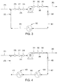
- FIG. 4 depicts schematic of another illustrative system 400 for controlling the temperature of a fluid during transport having two of the heat exchangers 100 depicted in FIG. 1 arranged in series with respect to one another, according to one or more embodiments. Similar to the system 300 in FIG. 3 , the system 400 depicted in FIG. 4 can include one or more flow lines (two are shown 370 , 385 ), one or more pumps 380 , and one or more recirculation loops 470 .
- the recirculation loop 470 can include two or more heat exchangers two are shown 100 A, 100 B) linked in series and one or more control or choke valves 490 . Although two heat exchangers 100 A and 100 B are shown in series more heat exchangers can be added in series, in parallel, or both.
- the recirculation loop 470 can be formed by a plurality of lines or conduits (three are shown 487 , 489 , 473 ). Fluid from the second flow line 385 can be introduced via a first line 487 to a first heat exchanger 100 A to produce a first cooled fluid via a second line 489 .
- the first cooled fluid can be introduced via the second line 489 to a second heat exchanger 100 B to produce a second cooled fluid via a third line 473 .
- the second cooled fluid via the third line 473 can be reintroduced to the first flow line 375 .
- the control valve 490 can be disposed in the first line 487 to regulate the amount of fluid flowing through the recirculation loop 470 .
- One or more first temperature sensors 376 , one or more first pressure sensors 377 , and one or more first flow meters 378 can be disposed on the first flow line 375 to measure the temperature, pressure, and flow rate of the fluid in the first flow line 375 .
- One or more second temperature sensors 381 , one or more second pressure sensors 382 , and one or more second flow meters 383 can be disposed on the second flow line 385 to measure the temperature, pressure, and flow rate of the pumped fluid in the second flow line 385 .
- a fluid e.g., a hydrocarbon fluid
- a fluid can be introduced via the first flow line 375 to the pump 380 to produce a pumped fluid via a second flow line 385 .
- the pumped fluid via the second flow line 385 can be transported to an alternate location, including, but not limited to, a production manifold, a boosting station, or the surface (e.g., a surface vessel or rig).
- the pump 380 can increase the pressure of the fluid introduced from the first flow line 375 to maintain the first flow rate of the fluid or increase the flow rate of the fluid to a second flow rate in the second flow line 385 .
- the recirculation loop 470 can be activated by at least partially opening the control valve 490 to increase flow through pump 380 and/or to maintain the temperature of the fluid in the second flow line 385 below a maximum design temperature of the system 400 or a desired temperature threshold. For example, when one or both of the flow meters 378 , 383 determine a decrease in the flow rate through the pump, the control valve 490 can be opened to activate the recirculation loop 470 . All or a portion of the fluid via line 385 can be diverted to the recirculation loop 470 .
- the heat exchangers 100 A, 100 B can cooperate to cool the fluid and thereby lower the pressure of the fluid flowing through the recirculation loop 470 .
- the control valve 490 can be at least partially opened to allow fluid to flow through the first heat exchanger 100 A and then through the second heat exchanger 100 B in the recirculation loop 470 .
- the sliding sleeves 120 of one or both of the heat exchangers 100 A, 100 B can be opened to allow more cooling element into the housings 115 of the heat exchangers 100 A, 100 B, without adjusting the amount of flow through the recirculation loop 470 .
- the maximum design temperature can range from a low of about 3° C., about 10° C., about 50° C., or about 100° C. to a high of about 150° C., about 200° C., about 250° C., or about 300° C. In another example, the maximum design temperature can be about 175° C. or less.
- heat exchangers 100 A, 100 B in series can effectively increase the surface area of the coils 110 .
- the two or more heat exchangers 100 A, 100 B in series can be used instead of a larger heat exchanger 100 having a larger coil 110 .
- Several smaller heat exchangers 100 can lower material and/or transport costs.
- large heat exchangers 100 can require large transport vessels and equipment to place them at the sea floor and/or wellhead, whereas two smaller heat exchangers 100 can be transported with a smaller vessel.
- Several heat exchangers 100 can also improve the robustness of the system 400 . For example, if one of the heat exchangers 100 should fail or require maintenance, the system 400 can continue via the bypass line(s) 107 of the inoperative heat exchanger 100 .
- the temperature sensors 131 , 132 in the heat exchangers 100 A, 100 B can measure the temperature of the fluid going in and out of each heat exchanger 100 A, 100 B.
- the heat exchangers 100 A, 100 B can cool the diverted fluid to a temperature equal to the first temperature of the fluid in the first flow line 375 , a third temperature below the first temperature measured in the first flow line 375 , or a fourth temperature between the first temperature measure in the first flow line 375 and the second temperature in the second flow line 385 .
- the sliding sleeves 120 of the heat exchangers 100 A, 100 B can be independently adjusted to allow heat transfer medium into the housing 115 of the heat exchangers 100 A, 100 B, thereby cooling the fluid to the first temperature measured in the flow line 375 .
- the sliding sleeves 120 of the heat exchangers 100 A, 100 B can be automatically adjusted for changes in temperature and pressure in the flow lines 375 and 385 .
- the sliding sleeve 120 of one or more of the heat exchangers 100 A, 100 B can be actuated to allow more of the heat transfer medium into the housing 115 and in contact with the coil 110 of each heat exchanger 100 A, 100 B. This can result in increased heat transfer by conduction, convection, or both. In this way, the first flow rate through the pump 380 can be maintained without a dramatic temperature increase in the system 400 .
- the recirculation loop 470 can provide additional flow to the first flow line 375 to maintain a minimum flow rate in the pump 380 for the reasons and advantages discussed and described above.
- FIG. 5 depicts a schematic of yet another illustrative system 500 for controlling the temperature of a fluid during transport having two of the heat exchangers 100 depicted in FIG. 1 arranged in parallel with respect to one another, according to one or more embodiments.
- the system 500 can include one or more flow lines (two are shown 370 , 385 ), one or more pumps 380 , and one or more recirculation loops 570 .
- the recirculation loop 570 can include two or more heat exchangers (two are shown 100 A, 100 C) linked in parallel and one or more control or choke valves (three are shown 590 , 591 , 592 ). Although two heat exchangers 100 A and 100 C are shown in parallel, more heat exchangers can be added in series, in parallel, or both.
- the recirculation loop 570 can be formed by a plurality of lines or conduits (six are shown 587 , 588 , 589 , 571 , 572 , 573 ) linking the heat exchangers 100 A, 100 C, the valves 590 , 591 , 592 , and the flow lines 375 , 385 .
- Fluid from the second flow line 385 can be introduced via a first line 587 and a second line 588 to the first heat exchanger 100 A to produce a first cooled fluid via a third line 571 .
- Fluid from the second flow line 385 can be introduced via the first line 587 and a fourth line 589 to a second heat exchanger 100 C to produce a second cooled fluid via a fifth line 572 .
- the third and fifth lines 571 and 572 can feed into a sixth line 573 , and the first cooled fluid, the second cooled fluid, or a mixture of both can be reintroduced via the sixth line 573 to the first flow line 375 .
- a first control valve 590 can be disposed in the first line 587 to regulate the amount of fluid flowing through the recirculation loop 570 .
- a second control valve 591 can be disposed in the second line 588 and can regulate the amount of fluid flowing to and/or cooled by the first heat exchanger 100 A.
- a third control valve 592 can be disposed in the second line 588 and can regulate the amount of fluid flowing to and/or cooled by the second heat exchanger 100 C.
- control lines can link control valves 590 , 591 , 592 to a control unit (not shown).
- the control unit can be disposed on the surface (e.g., a ship or a rig), proximate the pump 380 and the recirculation loop 570 , at another location, or at a combination thereof.
- the control valves 590 , 591 , 592 can be wirelessly linked to the control unit.
- the first temperature sensor 376 , the first pressure sensor 377 , and the first flow meter 378 can be disposed on the first flow line 375 to measure the temperature, pressure, and flow rate of the fluid in the first flow line 375 .
- the second temperature sensor 381 , the second pressure sensor 382 , and the second flow meter 383 can be disposed on the second flow line 385 to measure the temperature, pressure, and flow rate of the pumped fluid in the second flow line 385 .
- a fluid e.g., a hydrocarbon fluid
- the pumped fluid via the second flow line 385 can be transported to an alternate location, including, but not limited to, a production manifold, a boosting station, or the surface (e.g., a surface vessel or rig).
- the pump 380 can increase the pressure of the fluid introduced from the first flow line 375 to maintain the first flow rate of the fluid or increase the flow rate of the fluid to a second flow rate in the second flow line 385 .
- the first temperature, first pressure, and first flow rate in the first flow line 375 and the second flow rate in the second flow line 385 can be the same or similar to those discussed and described above.
- the recirculation loop 570 can be activated by at least partially opening the control valve 590 and one or more of the second and third control valves 591 , 592 to increase flow through pump 380 and/or to maintain the temperature of the fluid in the second flow line 385 below a maximum design temperature of the system 500 .
- the third control valve 592 can be closed to completely block the flow of fluid to the fourth line 589 and the second heat exchanger 100 C, thereby allowing fluid to only be cooled by the first heat exchanger 100 A.
- the second control valve 591 can be closed to completely block the flow of fluid to the second line 588 and the first heat exchanger 100 A, thereby allowing fluid to only be cooled by the second heat exchanger 100 C.
- the second control valve 591 and the third control valve 592 can both be opened to allow fluid through both heat exchangers 100 A and 100 C. All or a portion of the fluid via line 385 can be diverted to the recirculation loop 570 .
- the heat exchangers 100 A, 100 C can work independently or cooperate to cool the fluid and thereby lower the pressure of the fluid flowing through the recirculation loop 570 .
- the first control valve 590 and the second control valve 591 can be at least partially opened to allow fluid to flow through the first heat exchanger 100 A.
- the third control valve 592 can be at least partially opened to allow fluid to flow through the second heat exchanger 100 C.
- the sliding sleeves 120 of one or both of the heat exchangers 100 A, 100 C can be opened to allow more cooling element into the housings 115 of the heat exchangers 100 A, 100 C, without adjusting the amount of flow through the recirculation loop 570 .
- the maximum design temperature can range from a low of about 3° C. about 10° C., about 50° C., or about 100° C. to a high of about 150° C. about 200° C., about 250° C., or about 300° C.
- the maximum design temperature can be about 175° C. or less.
- Placing the heat exchangers 100 A, 100 C in parallel can effectively increase the surface area of the coils 110 .
- the two or more heat exchangers 100 A, 100 C in parallel can be used instead of a larger heat exchanger 100 having a larger coil 110 .
- Placing the heat exchangers 100 A, 100 C in parallel with the control valves 590 , 591 , 592 can allow flexible adjustment of the effective surface area of the coil 110 by activating one or more of the heat exchangers 100 A, 100 C.
- the temperature sensors 131 , 132 in the heat exchangers 100 A, 100 C can measure the temperature of the fluid going in and out of each heat exchanger 100 A, 100 C.
- the heat exchangers 100 A. 100 C can cool the diverted fluid to a temperature equal to the first temperature of the fluid in the first flow line 375 .
- the sliding sleeves 120 of the heat exchangers 100 A, 100 C can be adjusted to allow heat transfer medium into the housing 115 of the heat exchangers 100 A, 100 C, thereby cooling the fluid via the sixth line 573 to the first temperature in the flow line 375 .
- the sliding sleeves 120 of the heat exchangers 100 A, 100 C can be automatically adjusted for changes in temperature and pressure in the flow lines 375 and 385 .
- the temperature sensor 381 measures a temperature increase in the flow line 385
- the sliding sleeve 120 of one or more of the heat exchangers 100 A, 100 C can be actuated to allow more of the heat transfer medium into the housing 115 and in contact with the coil 110 of each heat exchanger 100 A, 100 C. This can result in increased heat transfer by conduction, convection, or both. In this way, the first flow rate through the pump 380 can be maintained without a dramatic temperature increase in the system 500 .
- the recirculation loop 570 can provide additional flow to the first flow line 375 to maintain a minimum flow rate in the pump 380 for the reasons and advantages discussed and described above.
- a method for transporting a hydrocarbon comprising introducing a fluid at a first pressure and a first temperature to an inlet of a pump; pressurizing the fluid within the pump to produce a pressurized fluid having a second pressure and a second temperature; and flowing at least a portion of the pressurized fluid through a first heat exchanger and back to the inlet of the pump, wherein the heat exchanger comprises: a coil having an inlet and an outlet; a housing at least partially enclosing the coil and having a first opening and a second opening, wherein a first end of the coil is disposed proximate the first opening; and a foundation for supporting the coil and the housing.
- a system for transporting a hydrocarbon comprising a pump having an inlet and an outlet; a recirculation loop joined to the outlet of the pump at a first end of the recirculation loop and joined to the inlet of the pump at a second end of the recirculation loop, the recirculation loop comprising: a heat exchanger; and a control valve disposed between the first end of the loop and the heat exchanger.
- the heat exchanger comprises: a coil having a fluid inlet and a fluid outlet; a housing at least partially enclosing the coil and having a first and a second opening, wherein a first end of the coil is disposed proximate the first opening; and a foundation for supporting the coil and the housing.
- the system of claim 10 further comprising one or more second temperature sensors, one or more second pressure sensors, one or more second flow meters or any combination thereof, wherein the one or more second temperature sensors, one or more second pressure sensors, and one or more second flow meters are each disposed proximate the outlet of the pump.
- An apparatus for exchanging heat between a fluid and a heat transfer medium comprising: a coil having an inlet and an outlet; a housing at least partially enclosing the coil and having a first opening and a second opening, wherein a first end of the coil is disposed proximate the first opening; and a foundation for supporting the coil and the housing.
Landscapes
- Engineering & Computer Science (AREA)
- Physics & Mathematics (AREA)
- Life Sciences & Earth Sciences (AREA)
- Geology (AREA)
- Mining & Mineral Resources (AREA)
- General Engineering & Computer Science (AREA)
- Mechanical Engineering (AREA)
- Thermal Sciences (AREA)
- Fluid Mechanics (AREA)
- Geochemistry & Mineralogy (AREA)
- General Life Sciences & Earth Sciences (AREA)
- Environmental & Geological Engineering (AREA)
- Ocean & Marine Engineering (AREA)
- Heat-Exchange Devices With Radiators And Conduit Assemblies (AREA)
- Filling Or Discharging Of Gas Storage Vessels (AREA)
- Structures Of Non-Positive Displacement Pumps (AREA)
- Jet Pumps And Other Pumps (AREA)
- Production Of Liquid Hydrocarbon Mixture For Refining Petroleum (AREA)
Abstract
Description
Claims (10)
Priority Applications (1)
| Application Number | Priority Date | Filing Date | Title |
|---|---|---|---|
| US14/694,056 US10627171B2 (en) | 2010-12-30 | 2015-04-23 | Submersed heat exchanger |
Applications Claiming Priority (2)
| Application Number | Priority Date | Filing Date | Title |
|---|---|---|---|
| US12/981,824 US9127897B2 (en) | 2010-12-30 | 2010-12-30 | Submersed heat exchanger |
| US14/694,056 US10627171B2 (en) | 2010-12-30 | 2015-04-23 | Submersed heat exchanger |
Related Parent Applications (1)
| Application Number | Title | Priority Date | Filing Date |
|---|---|---|---|
| US12/981,824 Division US9127897B2 (en) | 2010-12-30 | 2010-12-30 | Submersed heat exchanger |
Publications (2)
| Publication Number | Publication Date |
|---|---|
| US20150226361A1 US20150226361A1 (en) | 2015-08-13 |
| US10627171B2 true US10627171B2 (en) | 2020-04-21 |
Family
ID=46379718
Family Applications (2)
| Application Number | Title | Priority Date | Filing Date |
|---|---|---|---|
| US12/981,824 Active 2034-02-17 US9127897B2 (en) | 2010-12-30 | 2010-12-30 | Submersed heat exchanger |
| US14/694,056 Active US10627171B2 (en) | 2010-12-30 | 2015-04-23 | Submersed heat exchanger |
Family Applications Before (1)
| Application Number | Title | Priority Date | Filing Date |
|---|---|---|---|
| US12/981,824 Active 2034-02-17 US9127897B2 (en) | 2010-12-30 | 2010-12-30 | Submersed heat exchanger |
Country Status (4)
| Country | Link |
|---|---|
| US (2) | US9127897B2 (en) |
| NO (1) | NO340756B1 (en) |
| SE (1) | SE540636C2 (en) |
| WO (1) | WO2012091779A2 (en) |
Families Citing this family (20)
| Publication number | Priority date | Publication date | Assignee | Title |
|---|---|---|---|---|
| DE202010015516U1 (en) * | 2010-11-15 | 2012-02-29 | Uponor Innovation Ab | Control device for a heating system and heating system |
| FR2972894B1 (en) * | 2011-03-14 | 2013-04-26 | Converteam Technology Ltd | ENERGY CONVERTING DEVICE, IN PARTICULAR FOR A SUB-MARINE COMPRESSION AND PUMPING STATION, WITH IMPROVED COOLING MEANS |
| WO2013004277A1 (en) * | 2011-07-01 | 2013-01-10 | Statoil Petroleum As | Subsea heat exchanger and method for temperature control |
| WO2013134475A1 (en) * | 2012-03-07 | 2013-09-12 | Waters Technologies Corporation | Limiting a rate of pressurization in a pressurized flow system having a configurable system volume |
| NO342628B1 (en) * | 2012-05-24 | 2018-06-25 | Fmc Kongsberg Subsea As | Active control of underwater coolers |
| EP2959249B1 (en) * | 2013-02-22 | 2018-03-28 | Exxonmobil Upstream Research Company | Subwater heat exchanger |
| US20160130913A1 (en) * | 2013-06-06 | 2016-05-12 | Shell Oil Company | Subsea production cooler |
| US10234361B2 (en) | 2013-07-01 | 2019-03-19 | Knew Value Llc | Heat exchanger testing device |
| ES2759254T3 (en) * | 2013-07-01 | 2020-05-08 | Knew Value Llc | Procedure for monitoring a heat exchanger |
| US20150153074A1 (en) * | 2013-12-03 | 2015-06-04 | General Electric Company | System and method for controlling temperature of a working fluid |
| FI126014B (en) * | 2014-03-04 | 2016-05-31 | Uponor Infra Oy | Low temperature heat exchanger |
| US9366112B2 (en) * | 2014-04-23 | 2016-06-14 | Shell Oil Company | Subsea production cooler with gas lift |
| WO2016123340A1 (en) * | 2015-01-30 | 2016-08-04 | Bp Corporation North America, Inc. | Subsea heat exchangers for offshore hydrocarbon production operations |
| ITUB20152051A1 (en) * | 2015-07-10 | 2017-01-10 | Nuovo Pignone Srl | Submarine group |
| US9897386B2 (en) | 2015-08-10 | 2018-02-20 | Indmar Products Company Inc. | Marine engine heat exchanger |
| US9896911B2 (en) * | 2016-01-26 | 2018-02-20 | Trendsetter Vulcan Offshore, Inc. | Subsea pressure protection system |
| FI20175984A1 (en) * | 2017-11-06 | 2019-05-07 | Wasenco Oy | Method and control system for controlling the recovery of heat energy from waste water flowing in a spiral pipe located inside a container |
| CN109855442B (en) * | 2018-12-29 | 2024-02-27 | 上海工程技术大学 | Medium participation radiation heating gasification device |
| CN113153223B (en) * | 2021-03-23 | 2022-03-22 | 河北省地矿局第三水文工程地质大队 | Sandstone-type water outlet geothermal well and recharge well construction method |
| KR102685805B1 (en) * | 2023-12-19 | 2024-07-17 | 주식회사 스마트파워 | Variable intercooler with improved heat exchange efficiency |
Citations (26)
| Publication number | Priority date | Publication date | Assignee | Title |
|---|---|---|---|---|
| US3211217A (en) * | 1963-07-12 | 1965-10-12 | Westinghouse Electric Corp | Fluid reversing valve structure |
| US3251401A (en) * | 1964-05-11 | 1966-05-17 | M B Gardner Co Inc | Heat exchanger |
| US3384169A (en) | 1966-05-17 | 1968-05-21 | Mobil Oil Corp | Underwater low temperature separation unit |
| US5573060A (en) * | 1991-02-27 | 1996-11-12 | Rolls-Royce And Associates Limited | Heat exchanger |
| US5803161A (en) * | 1996-09-04 | 1998-09-08 | The Babcock & Wilcox Company | Heat pipe heat exchanger for cooling or heating high temperature/high-pressure sub-sea well streams |
| US6142215A (en) * | 1998-08-14 | 2000-11-07 | Edg, Incorporated | Passive, thermocycling column heat-exchanger system |
| US6279658B1 (en) | 1996-10-08 | 2001-08-28 | Baker Hughes Incorporated | Method of forming and servicing wellbores from a main wellbore |
| US6302191B1 (en) | 1998-06-08 | 2001-10-16 | Alstom Uk Limited | Heat exchanger |
| US20030011289A1 (en) | 2001-07-13 | 2003-01-16 | Carrier Corporation | Detachable frame for coil removal |
| US6880638B2 (en) * | 2000-12-04 | 2005-04-19 | Triangle Equipment Ag | Device for an opening in an outer sleeve of a sleeve valve and a method for the assembly of a sleeve valve |
| US6978825B1 (en) * | 1998-12-31 | 2005-12-27 | Bouygues Offshore | Device and process for the heat insulation of at least one underwater pipe at great depth |
| US7258323B2 (en) * | 2005-06-15 | 2007-08-21 | Schlumberger Technology Corporation | Variable radial flow rate control system |
| WO2008004886A1 (en) | 2006-07-07 | 2008-01-10 | Norsk Hydro Produksjon A.S. | Heat exchanger with cooling fins |
| US7377039B2 (en) * | 2003-05-29 | 2008-05-27 | Saudi Arabian Oil Company | Anti-corrosion protection for heat exchanger tube sheet and method of manufacture |
| WO2008147219A2 (en) * | 2007-06-01 | 2008-12-04 | Fmc Kongsberg Subsea As | Subsea cooler |
| US20090031448A1 (en) | 2001-06-22 | 2009-01-29 | Pioneer Hi-Bred International, Inc. | Defensin polynucleotides and methods of use |
| US7530398B2 (en) | 2004-12-20 | 2009-05-12 | Shell Oil Company | Method and apparatus for a cold flow subsea hydrocarbon production system |
| US20090185867A1 (en) | 2008-01-18 | 2009-07-23 | Masters Rodney H | Marine anti-foulant system and methods for using same |
| US20090277612A1 (en) * | 2006-07-07 | 2009-11-12 | Edwin Poorte | Underwater cooling assembly |
| WO2010002272A1 (en) | 2008-07-03 | 2010-01-07 | Aker Subsea As | Subsea heat exchanger |
| US20100006291A1 (en) * | 2006-07-07 | 2010-01-14 | Edwin Poorte | Method of cooling a multiphase well effluent stream |
| US20100012325A1 (en) * | 2008-07-17 | 2010-01-21 | Vetco Gray Scandinavia As | System and method for sub-cooling hydrocarbon production fluid for transport |
| US7845411B2 (en) | 2006-10-20 | 2010-12-07 | Shell Oil Company | In situ heat treatment process utilizing a closed loop heating system |
| US20100329908A1 (en) * | 2009-06-29 | 2010-12-30 | Baker Hughes Incorporated | Heat exchanger for esp motor |
| US20110209848A1 (en) * | 2008-09-24 | 2011-09-01 | Earth To Air Systems, Llc | Heat Transfer Refrigerant Transport Tubing Coatings and Insulation for a Direct Exchange Geothermal Heating/Cooling System and Tubing Spool Core Size |
| US20120097362A1 (en) * | 2009-03-27 | 2012-04-26 | Framo Engineering As | Subsea cooler and method for cleaning the subsea cooler |
Family Cites Families (21)
| Publication number | Priority date | Publication date | Assignee | Title |
|---|---|---|---|---|
| US1735498A (en) * | 1926-12-20 | 1929-11-12 | Joseph M Etienne | Refrigerating apparatus |
| US2082549A (en) * | 1934-08-14 | 1937-06-01 | Kelvinator Corp | Refrigerating apparatus |
| US2062054A (en) * | 1935-04-26 | 1936-11-24 | Westinghouse Electric & Mfg Co | Air conditioning apparatus |
| US3744935A (en) * | 1971-10-07 | 1973-07-10 | Crane Co | Cooling systems for motor driven pumps and the like |
| US4025239A (en) * | 1975-12-30 | 1977-05-24 | Carrier Corporation | Reciprocating compressors |
| US4248055A (en) * | 1979-01-15 | 1981-02-03 | Borg-Warner Corporation | Hot gas bypass control for centrifugal liquid chillers |
| HU180147B (en) * | 1980-06-12 | 1983-02-28 | Huetoetechnika Ipari Szoevetke | Heat exchanger |
| US4603559A (en) * | 1985-07-08 | 1986-08-05 | Wu Ming W | Water-cooled air conditioner |
| US4676071A (en) * | 1986-04-17 | 1987-06-30 | Latimer Maurice E | Water cooled refrigerant condenser |
| US5018665A (en) * | 1990-02-13 | 1991-05-28 | Hale Fire Pump Company | Thermal relief valve |
| US5139393A (en) * | 1990-02-13 | 1992-08-18 | Hale Fire Pump Company | Thermal relief valve |
| US5277028A (en) * | 1990-03-26 | 1994-01-11 | Mercedes-Benz Ag | Hydraulic flow control with temperature sensitive spring biased bypass valve |
| US5509272A (en) * | 1991-03-08 | 1996-04-23 | Hyde; Robert E. | Apparatus for dehumidifying air in an air-conditioned environment with climate control system |
| US5167491A (en) * | 1991-09-23 | 1992-12-01 | Carrier Corporation | High to low side bypass to prevent reverse rotation |
| CH684965A5 (en) * | 1991-10-18 | 1995-02-15 | Linde Ag | Method and apparatus for increasing the efficiency of compression devices. |
| US5248244A (en) * | 1992-12-21 | 1993-09-28 | Carrier Corporation | Scroll compressor with a thermally responsive bypass valve |
| JP3356480B2 (en) * | 1993-03-18 | 2002-12-16 | 株式会社日本触媒 | Leakless pump |
| US5832739A (en) * | 1996-11-26 | 1998-11-10 | Rti Inc. | Heat exchanger for evaporative cooling refrigeration system |
| US6202431B1 (en) * | 1999-01-15 | 2001-03-20 | York International Corporation | Adaptive hot gas bypass control for centrifugal chillers |
| US6595011B1 (en) * | 2002-05-02 | 2003-07-22 | Linda Forgy Chaney | Water cooled air conditioner |
| US6959558B2 (en) * | 2003-03-06 | 2005-11-01 | American Power Conversion Corp. | Systems and methods for head pressure control |
-
2010
- 2010-12-30 US US12/981,824 patent/US9127897B2/en active Active
-
2011
- 2011-10-11 SE SE1350920A patent/SE540636C2/en active IP Right Revival
- 2011-10-11 WO PCT/US2011/055763 patent/WO2012091779A2/en not_active Ceased
-
2013
- 2013-07-30 NO NO20131052A patent/NO340756B1/en unknown
-
2015
- 2015-04-23 US US14/694,056 patent/US10627171B2/en active Active
Patent Citations (28)
| Publication number | Priority date | Publication date | Assignee | Title |
|---|---|---|---|---|
| US3211217A (en) * | 1963-07-12 | 1965-10-12 | Westinghouse Electric Corp | Fluid reversing valve structure |
| US3251401A (en) * | 1964-05-11 | 1966-05-17 | M B Gardner Co Inc | Heat exchanger |
| US3384169A (en) | 1966-05-17 | 1968-05-21 | Mobil Oil Corp | Underwater low temperature separation unit |
| US5573060A (en) * | 1991-02-27 | 1996-11-12 | Rolls-Royce And Associates Limited | Heat exchanger |
| US5803161A (en) * | 1996-09-04 | 1998-09-08 | The Babcock & Wilcox Company | Heat pipe heat exchanger for cooling or heating high temperature/high-pressure sub-sea well streams |
| US6279658B1 (en) | 1996-10-08 | 2001-08-28 | Baker Hughes Incorporated | Method of forming and servicing wellbores from a main wellbore |
| US6302191B1 (en) | 1998-06-08 | 2001-10-16 | Alstom Uk Limited | Heat exchanger |
| US6142215A (en) * | 1998-08-14 | 2000-11-07 | Edg, Incorporated | Passive, thermocycling column heat-exchanger system |
| US6978825B1 (en) * | 1998-12-31 | 2005-12-27 | Bouygues Offshore | Device and process for the heat insulation of at least one underwater pipe at great depth |
| US6880638B2 (en) * | 2000-12-04 | 2005-04-19 | Triangle Equipment Ag | Device for an opening in an outer sleeve of a sleeve valve and a method for the assembly of a sleeve valve |
| US20090031448A1 (en) | 2001-06-22 | 2009-01-29 | Pioneer Hi-Bred International, Inc. | Defensin polynucleotides and methods of use |
| US20030011289A1 (en) | 2001-07-13 | 2003-01-16 | Carrier Corporation | Detachable frame for coil removal |
| US7377039B2 (en) * | 2003-05-29 | 2008-05-27 | Saudi Arabian Oil Company | Anti-corrosion protection for heat exchanger tube sheet and method of manufacture |
| US7530398B2 (en) | 2004-12-20 | 2009-05-12 | Shell Oil Company | Method and apparatus for a cold flow subsea hydrocarbon production system |
| US7258323B2 (en) * | 2005-06-15 | 2007-08-21 | Schlumberger Technology Corporation | Variable radial flow rate control system |
| WO2008004886A1 (en) | 2006-07-07 | 2008-01-10 | Norsk Hydro Produksjon A.S. | Heat exchanger with cooling fins |
| US20100006291A1 (en) * | 2006-07-07 | 2010-01-14 | Edwin Poorte | Method of cooling a multiphase well effluent stream |
| US20090277612A1 (en) * | 2006-07-07 | 2009-11-12 | Edwin Poorte | Underwater cooling assembly |
| US7845411B2 (en) | 2006-10-20 | 2010-12-07 | Shell Oil Company | In situ heat treatment process utilizing a closed loop heating system |
| WO2008147219A2 (en) * | 2007-06-01 | 2008-12-04 | Fmc Kongsberg Subsea As | Subsea cooler |
| US20100252227A1 (en) | 2007-06-01 | 2010-10-07 | Fmc Kongsberg Subsea As | Subsea cooler |
| US20090185867A1 (en) | 2008-01-18 | 2009-07-23 | Masters Rodney H | Marine anti-foulant system and methods for using same |
| WO2010002272A1 (en) | 2008-07-03 | 2010-01-07 | Aker Subsea As | Subsea heat exchanger |
| US20110100589A1 (en) * | 2008-07-03 | 2011-05-05 | Bastiaen Van Der Rest | Subsea heat exchanger |
| US20100012325A1 (en) * | 2008-07-17 | 2010-01-21 | Vetco Gray Scandinavia As | System and method for sub-cooling hydrocarbon production fluid for transport |
| US20110209848A1 (en) * | 2008-09-24 | 2011-09-01 | Earth To Air Systems, Llc | Heat Transfer Refrigerant Transport Tubing Coatings and Insulation for a Direct Exchange Geothermal Heating/Cooling System and Tubing Spool Core Size |
| US20120097362A1 (en) * | 2009-03-27 | 2012-04-26 | Framo Engineering As | Subsea cooler and method for cleaning the subsea cooler |
| US20100329908A1 (en) * | 2009-06-29 | 2010-12-30 | Baker Hughes Incorporated | Heat exchanger for esp motor |
Also Published As
| Publication number | Publication date |
|---|---|
| SE1350920A1 (en) | 2013-08-27 |
| WO2012091779A2 (en) | 2012-07-05 |
| NO20131052A1 (en) | 2013-09-25 |
| WO2012091779A3 (en) | 2014-01-30 |
| SE540636C2 (en) | 2018-10-09 |
| US20120168142A1 (en) | 2012-07-05 |
| US20150226361A1 (en) | 2015-08-13 |
| NO340756B1 (en) | 2017-06-12 |
| US9127897B2 (en) | 2015-09-08 |
Similar Documents
| Publication | Publication Date | Title |
|---|---|---|
| US10627171B2 (en) | Submersed heat exchanger | |
| US8016030B1 (en) | Apparatus and method for containing oil from a deep water oil well | |
| AU2012253232B2 (en) | Subsea cooling system | |
| US8734056B2 (en) | Underwater hydrocarbon transport and temperature control device | |
| US10273785B2 (en) | Process for remediating hydrates from subsea flowlines | |
| EA012681B1 (en) | Apparatus for extracting, cooling and transporting effluents produced by an undersea well (embodiments) | |
| KR102096582B1 (en) | Underwater heat exchanger system using water current and water heat and method for constructing this same | |
| US20030138299A1 (en) | Cooling water system | |
| EP2877685A1 (en) | Active control of subsea coolers | |
| BR112014004839B1 (en) | METHOD FOR BUILDING AN FPSO AND SYSTEM FOR INSTALLING A PRE-ASSEMBLY AND PRE-INTEGRATED MODULE ASSEMBLY ON A SHIP ARRAYED IN A BODY OF WATER TO FORM AN FPSO | |
| EP3548695B1 (en) | Regulating the temperature of a subsea process flow | |
| US11486229B2 (en) | Cooling fluid circulation systems for offshore production operations | |
| US4357989A (en) | Heat exchange circuit for an offshore installation | |
| US3324875A (en) | Valve | |
| WO2022182246A1 (en) | System and method for transmitting subsea parameters | |
| AU2014274938B2 (en) | Subsea production cooler | |
| JP2016215151A (en) | Fluid separation device and fluid separation method | |
| US20220144404A1 (en) | Sea water intake riser system | |
| WO2023009053A1 (en) | Seawater cooling system and cooling method | |
| US9366112B2 (en) | Subsea production cooler with gas lift | |
| US20260043208A1 (en) | Systems and methods for subsea biofouling reduction | |
| KR101359517B1 (en) | Subsea Manifold | |
| WO2003037703A1 (en) | An apparatus for supply of cooling water from the sea to a process aboard a turret-anchored vessel | |
| CN110167836A (en) | floating structure | |
| KR20160077309A (en) | Dynamic Behavior Reduction Apparatus for Turret |
Legal Events
| Date | Code | Title | Description |
|---|---|---|---|
| AS | Assignment |
Owner name: BANK OF AMERICA, N.A., AS ADMINISTRATIVE AGENT, NORTH CAROLINA Free format text: SECURITY INTEREST;ASSIGNOR:KELLOGG BROWN & ROOT LLC;REEL/FRAME:046022/0413 Effective date: 20180425 Owner name: BANK OF AMERICA, N.A., AS ADMINISTRATIVE AGENT, NO Free format text: SECURITY INTEREST;ASSIGNOR:KELLOGG BROWN & ROOT LLC;REEL/FRAME:046022/0413 Effective date: 20180425 |
|
| STPP | Information on status: patent application and granting procedure in general |
Free format text: NON FINAL ACTION MAILED |
|
| STPP | Information on status: patent application and granting procedure in general |
Free format text: RESPONSE TO NON-FINAL OFFICE ACTION ENTERED AND FORWARDED TO EXAMINER |
|
| STPP | Information on status: patent application and granting procedure in general |
Free format text: FINAL REJECTION MAILED |
|
| STPP | Information on status: patent application and granting procedure in general |
Free format text: ADVISORY ACTION MAILED |
|
| STPP | Information on status: patent application and granting procedure in general |
Free format text: NOTICE OF ALLOWANCE MAILED -- APPLICATION RECEIVED IN OFFICE OF PUBLICATIONS |
|
| STCF | Information on status: patent grant |
Free format text: PATENTED CASE |
|
| MAFP | Maintenance fee payment |
Free format text: PAYMENT OF MAINTENANCE FEE, 4TH YEAR, LARGE ENTITY (ORIGINAL EVENT CODE: M1551); ENTITY STATUS OF PATENT OWNER: LARGE ENTITY Year of fee payment: 4 |