US10627030B2 - Reverse barb for medical biopharma tubing - Google Patents
Reverse barb for medical biopharma tubing Download PDFInfo
- Publication number
- US10627030B2 US10627030B2 US16/236,465 US201816236465A US10627030B2 US 10627030 B2 US10627030 B2 US 10627030B2 US 201816236465 A US201816236465 A US 201816236465A US 10627030 B2 US10627030 B2 US 10627030B2
- Authority
- US
- United States
- Prior art keywords
- fluid
- barbed
- clamping
- flexible tubing
- fitting
- Prior art date
- Legal status (The legal status is an assumption and is not a legal conclusion. Google has not performed a legal analysis and makes no representation as to the accuracy of the status listed.)
- Expired - Fee Related, expires
Links
Images


Classifications
-
- F—MECHANICAL ENGINEERING; LIGHTING; HEATING; WEAPONS; BLASTING
- F16—ENGINEERING ELEMENTS AND UNITS; GENERAL MEASURES FOR PRODUCING AND MAINTAINING EFFECTIVE FUNCTIONING OF MACHINES OR INSTALLATIONS; THERMAL INSULATION IN GENERAL
- F16L—PIPES; JOINTS OR FITTINGS FOR PIPES; SUPPORTS FOR PIPES, CABLES OR PROTECTIVE TUBING; MEANS FOR THERMAL INSULATION IN GENERAL
- F16L33/00—Arrangements for connecting hoses to rigid members; Rigid hose-connectors, i.e. single members engaging both hoses
- F16L33/22—Arrangements for connecting hoses to rigid members; Rigid hose-connectors, i.e. single members engaging both hoses with means not mentioned in the preceding groups for gripping the hose between inner and outer parts
- F16L33/23—Arrangements for connecting hoses to rigid members; Rigid hose-connectors, i.e. single members engaging both hoses with means not mentioned in the preceding groups for gripping the hose between inner and outer parts the outer parts being segmented, the segments being pressed against the hose by tangentially arranged members
-
- A—HUMAN NECESSITIES
- A61—MEDICAL OR VETERINARY SCIENCE; HYGIENE
- A61M—DEVICES FOR INTRODUCING MEDIA INTO, OR ONTO, THE BODY; DEVICES FOR TRANSDUCING BODY MEDIA OR FOR TAKING MEDIA FROM THE BODY; DEVICES FOR PRODUCING OR ENDING SLEEP OR STUPOR
- A61M39/00—Tubes, tube connectors, tube couplings, valves, access sites or the like, specially adapted for medical use
- A61M39/10—Tube connectors; Tube couplings
- A61M39/1011—Locking means for securing connection; Additional tamper safeties
-
- A—HUMAN NECESSITIES
- A61—MEDICAL OR VETERINARY SCIENCE; HYGIENE
- A61M—DEVICES FOR INTRODUCING MEDIA INTO, OR ONTO, THE BODY; DEVICES FOR TRANSDUCING BODY MEDIA OR FOR TAKING MEDIA FROM THE BODY; DEVICES FOR PRODUCING OR ENDING SLEEP OR STUPOR
- A61M39/00—Tubes, tube connectors, tube couplings, valves, access sites or the like, specially adapted for medical use
- A61M39/10—Tube connectors; Tube couplings
- A61M39/12—Tube connectors; Tube couplings for joining a flexible tube to a rigid attachment
-
- F—MECHANICAL ENGINEERING; LIGHTING; HEATING; WEAPONS; BLASTING
- F16—ENGINEERING ELEMENTS AND UNITS; GENERAL MEASURES FOR PRODUCING AND MAINTAINING EFFECTIVE FUNCTIONING OF MACHINES OR INSTALLATIONS; THERMAL INSULATION IN GENERAL
- F16L—PIPES; JOINTS OR FITTINGS FOR PIPES; SUPPORTS FOR PIPES, CABLES OR PROTECTIVE TUBING; MEANS FOR THERMAL INSULATION IN GENERAL
- F16L33/00—Arrangements for connecting hoses to rigid members; Rigid hose-connectors, i.e. single members engaging both hoses
- F16L33/02—Hose-clips
- F16L33/12—Hose-clips with a pivoted or swinging tightening or securing member, e.g. toggle lever
-
- F—MECHANICAL ENGINEERING; LIGHTING; HEATING; WEAPONS; BLASTING
- F16—ENGINEERING ELEMENTS AND UNITS; GENERAL MEASURES FOR PRODUCING AND MAINTAINING EFFECTIVE FUNCTIONING OF MACHINES OR INSTALLATIONS; THERMAL INSULATION IN GENERAL
- F16L—PIPES; JOINTS OR FITTINGS FOR PIPES; SUPPORTS FOR PIPES, CABLES OR PROTECTIVE TUBING; MEANS FOR THERMAL INSULATION IN GENERAL
- F16L2201/00—Special arrangements for pipe couplings
- F16L2201/40—Special arrangements for pipe couplings for special environments
- F16L2201/44—Special arrangements for pipe couplings for special environments sterile
Definitions
- the present invention generally relates to fluid connectors and, more specifically to barbed fluid connectors.
- the invention provides a fluid connector comprising first and second curved clamping portions coupled together for movement between an open condition and a closed, clamping condition for clamping an end of a length of flexible tubing to a fluid fitting.
- the first and second clamping portions each have a curved interior surface and at least one barb on each curved interior surface. The barbs are configured to engage the exterior surface of the flexible tubing when the first and second clamping portions are in the closed, clamping condition to form a fluid tight connection between the fluid fitting and the flexible tubing.
- a fluid system comprises first and second clamping portions coupled together for movement between an open condition and a closed, clamping condition.
- the first and second clamping portions each have a curved interior surface and at least one barb on each curved interior surface.
- the system further includes a length of flexible tubing, and a fluid fitting configured to receive an end of the length of flexible tubing. The barbs of the first and second clamping portions engage the exterior surface of the flexible tubing when the first and second clamping portions are in the closed, clamping condition to form a fluid tight connection between the fluid fitting and the flexible tubing.
- a method of forming a fluid tight connection between a length of flexible tubing and a fluid fitting includes directing the end of a length of flexible tubing over a fluid fitting to form fluid passage communicating from the flexible tubing through the fluid fitting.
- a fluid connector is placed around the end of the length of flexible tubing.
- the first and second clamping portions of the fluid connector are moved into a clamping condition onto the exterior surface of the flexible tubing. At least one barb on an interior surface of the first and second clamping portions engages into the exterior surface of the flexible tubing when the fluid connector is in the clamping condition to thereby form a fluid tight connection between the flexible tubing and the fluid fitting.
- FIG. 1 is a perspective view of an illustrative embodiment of a fluid connector in accordance with an illustrative embodiment of the invention coupled to a length of flexible tubing.
- FIG. 2 is a cross sectional view taken along line 2 - 2 of FIG. 1 .
- FIG. 3 is a disassembled perspective view of the connector and tubing of FIG. 1 .
- FIG. 4 is a lengthwise axial cross sectional view of the assembly shown in FIG. 3 .
- FIG. 5 is a perspective view similar to FIG. 1 , but showing the connector in an open condition.
- FIG. 6 is a lengthwise axial cross sectional view of the assembly shown in FIG. 5 .
- FIG. 7 is a perspective view similar to FIG. 5 , but showing the connector in the process of being clamped onto the tubing and an underlying fluid fitting.
- FIG. 8A is a top view of the assembly shown in FIG. 3 .
- FIG. 8B is a cross sectional view taken along line 8 B- 8 B of FIG. 5 .
- FIG. 8C is a cross sectional view taken along line 8 C- 8 C of FIG. 7 .
- FIG. 8D is a cross sectional view taken along line 8 D- 8 D of FIG. 1 .
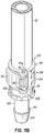
- FIG. 9 is a perspective view of another illustrative embodiment of a fluid connector according to the invention.
- FIG. 10 is a perspective view of the connector illustrated in FIG. 9 , but with the connector rotated approximately 90°.
- FIG. 11A is a perspective view illustrating the fluid connector of FIG. 9 assembled to a length of tubing and being coupled with a barbed fluid fitting.
- FIG. 11B is a perspective view similar to FIG. 11A but illustrating the fluid connector in the closed or clamped condition on the tubing and fluid fitting.
- FIG. 12 is a lengthwise axial cross sectional view of the assembled tubing, connector, and fluid fitting shown in FIG. 11B .
- FIG. 13A is a cross sectional view taken along line 13 A- 13 A of FIG. 9 .
- FIG. 13B is a cross sectional view similar to FIG. 13A , but illustrating the latched or closed condition of the connector.
- FIGS. 1 and 2 An illustrative embodiment of a fluid connector 10 for medical, biopharma or other fluid connection applications is shown in FIGS. 1 and 2 .
- the connector 10 may be made from any suitable material, such as medical grade polymer(s).
- FIG. 1 illustrates an assembly including the connector 10 used for coupling a length of flexible tubing 12 , such as resilient silicone tubing, to a fluid fitting such as a sanitary fitting 14 .
- the connector 10 , tubing 12 and fitting 14 comprise a fluid system, although it will be understood that such as system may comprise further components and fluid components having a wide variety of designs and uses. As shown in more detail in the cross sectional view of FIG.
- the end 12 a of the medical tubing 12 is placed over a more rigid cylindrical extension 16 of the sanitary fitting 14 and within a shallow annular recess 20 .
- the end 12 a may be received on the extension 16 with a friction fit or more loosely, depending on the applied clamping force of the connector 10 .
- the recess 20 is formed between the cylindrical extension 16 and an upstanding annular flange 22 .
- the connector 10 is formed with two clamp arms 30 , 32 coupled together by a hinge or pivot 34 ( FIG. 3 ). As further shown best in FIG. 3 , the semi-cylindrical inner surfaces 30 a , 32 a of the clamp arms 30 , 32 include barbs 36 .
- Each clamp arm 30 , 32 include a shroud 38 , 40 that secures onto the flange 22 of the sanitary fitting 14 .
- the shrouds 38 , 40 increase the pull off force of the tubing 12 and allow any pulling force on the tubing 12 to be spread away from the hinge or pivot 34 to reduce the likelihood that the hinge or pivot 34 will deform or fracture under such force.
- the connector 10 includes a suitable coupling element for securing the clamp arms 30 , 32 around the tubing 12 as shown in FIG. 1 .
- the coupling element is an over center clasp mechanism 50 .
- the sanitary fitting 14 may be a fluid fitting of any suitable design, other than that shown in the illustrative embodiment. Such sanitary fittings are designed to mate with other sanitary fittings using a gasket and a clamp (not shown). It will be understood that aspects and features of the present invention may be used to facilitate fluid tight connections between lengths of tubing and other types of fittings, such as fittings on other fluid components, or even fittings to connect other lengths of tubing.
- each clamp arm 30 , 32 Although two barbs 36 are shown on the interior surface of each clamp arm 30 , 32 , only one barb 36 may be provided on each clamp arm 30 , 32 depending on the application, and there may be other applications in which more than two barbs 36 are desired or necessary.
- the use an over center clasp mechanism 50 such as the one illustrated in the drawings, provides mechanical advantage when clamping and locking the clamp arms 30 , 32 onto the outer surface of the tubing 12 . In this manner, the user is able to apply significant clamping force with reduced effort.
- FIGS. 4-7 illustrate a procedure for coupling a length of resilient medical tubing 12 , such as silicone tubing, to a sanitary fitting 14 using a reverse barb connector 10 .
- the end 12 a of the tubing 12 is directed over the extension 16 as shown by the arrows 60 .
- the connector 10 is opened and placed around the end 12 a of the tubing 12 as well as the extension 16 and annular flange 22 in the position shown.
- the two clamp arms 30 , 32 are pivoted toward one another as shown by the arrows 62 in FIG. 6 .
- the annular flange 22 is received by the semi-annular shrouds 38 , 40 of each clamp arm 30 , 32 as shown in FIGS. 6 and 7 .
- a pivotal clasp element 64 coupled with one of the clamp arms 30 is directed through a buckle element 66 pivotally coupled with the other clamp arm 32 .
- the components 64 , 66 of the clamp mechanism 50 rotate about axes that are at least generally parallel to the longitudinal axis 68 of the tubing 12 (see FIGS. 4 and 6 ).
- FIGS. 8A-8D The connection method is also illustrated in FIGS. 8A-8D .
- FIG. 8A corresponds generally to the open condition of the connector 10 shown in FIG. 4 prior to receiving the tubing 12 .
- FIG. 8B corresponds generally to the condition to the connector 10 as shown in FIG. 5 with the tubing 12 in place on the extension 16 of the sanitary fitting 14 and the clamp arms 30 , 32 being brought together around the tubing 12 as well as the connecting portion of the sanitary fitting 14 .
- FIG. 8C illustrates the point in the method of coupling during which the clasp element 64 is directed through the buckle element 66 and the direction of rotation initiated by the user, and shown by the arrows 70 , for bringing the clamp arms 30 , 32 together with an over center mechanical advantage.
- FIG. 8D then illustrates the final position of the clasp element 64 locked into place with the clamp arms 30 , 32 firmly engaging the exterior surface of the tubing 12 and the barbs 36 biting into that exterior surface of the tubing 12 as illustrated by the dashed lines
- a reverse barb fluid connector 100 in this embodiment includes a one piece clamping body 102 that has a generally cylindrical cage-type structure. Clamping members 104 are spaced apart along the body 102 and at least one of these clamping members 104 includes a barb 106 similar to the barbs 36 shown and described with regard to the first embodiment.
- the connector 100 may be used to connect conventional silicone medical tubing 12 to a conventional barbed sanitary fitting 108 .
- the connector body 102 is preferably formed from a flexible medical grade polymeric material, such as USP Class 6 glass-filled Nylon, or USP Class 6 polypropylene and is flexible enough such that it may be flexed opened and placed around an existing fluid fitting/tubing assembly as shown best in FIG. 12 .
- the fluid fitting 108 and the tubing 12 may remain attached to each other as the connector 100 is clamped into place thereby maintaining sterility and fluid integrity of the system.
- the connector 100 is formed with a buckle connector 110 integrally molded with the body 102 , and a pivoting clasp 112 .
- the clasp 112 has a pin 114 at one end and an attached latch member 116 that couples with the buckle connector 110 .
- An opening 120 is located between pin receiving elements 113 a , 113 b and the buckle connector 110 for receiving the tubing 12 during assembly.
- the buckle connector 110 has an over center movement as best illustrated in FIGS. 13A and 13B .
- the connector body 102 may be flexed such that the opening 120 is large enough to receive the tubing 12 when it is already coupled to the underlying fluid fitting 108 . This results in the assembly as shown in FIG. 13A .
- the buckle connector 110 is coupled or placed into a groove 126 of the clasp 112 and the clasp 112 is pivoted to the position shown in FIG. 13B with the action of an over center buckle assembly.
Landscapes
- Health & Medical Sciences (AREA)
- Engineering & Computer Science (AREA)
- Heart & Thoracic Surgery (AREA)
- General Engineering & Computer Science (AREA)
- Hematology (AREA)
- Biomedical Technology (AREA)
- Anesthesiology (AREA)
- Life Sciences & Earth Sciences (AREA)
- Animal Behavior & Ethology (AREA)
- General Health & Medical Sciences (AREA)
- Public Health (AREA)
- Veterinary Medicine (AREA)
- Pulmonology (AREA)
- Mechanical Engineering (AREA)
- Infusion, Injection, And Reservoir Apparatuses (AREA)
Abstract
Description
Claims (18)
Priority Applications (1)
| Application Number | Priority Date | Filing Date | Title |
|---|---|---|---|
| US16/236,465 US10627030B2 (en) | 2014-04-24 | 2018-12-29 | Reverse barb for medical biopharma tubing |
Applications Claiming Priority (3)
| Application Number | Priority Date | Filing Date | Title |
|---|---|---|---|
| US201461983701P | 2014-04-24 | 2014-04-24 | |
| US14/693,238 US10203058B2 (en) | 2014-04-24 | 2015-04-22 | Reverse barb fluid connector and method of fluid connection |
| US16/236,465 US10627030B2 (en) | 2014-04-24 | 2018-12-29 | Reverse barb for medical biopharma tubing |
Related Parent Applications (1)
| Application Number | Title | Priority Date | Filing Date |
|---|---|---|---|
| US14/693,238 Continuation US10203058B2 (en) | 2014-04-24 | 2015-04-22 | Reverse barb fluid connector and method of fluid connection |
Publications (2)
| Publication Number | Publication Date |
|---|---|
| US20190137020A1 US20190137020A1 (en) | 2019-05-09 |
| US10627030B2 true US10627030B2 (en) | 2020-04-21 |
Family
ID=54334382
Family Applications (2)
| Application Number | Title | Priority Date | Filing Date |
|---|---|---|---|
| US14/693,238 Expired - Fee Related US10203058B2 (en) | 2014-04-24 | 2015-04-22 | Reverse barb fluid connector and method of fluid connection |
| US16/236,465 Expired - Fee Related US10627030B2 (en) | 2014-04-24 | 2018-12-29 | Reverse barb for medical biopharma tubing |
Family Applications Before (1)
| Application Number | Title | Priority Date | Filing Date |
|---|---|---|---|
| US14/693,238 Expired - Fee Related US10203058B2 (en) | 2014-04-24 | 2015-04-22 | Reverse barb fluid connector and method of fluid connection |
Country Status (1)
| Country | Link |
|---|---|
| US (2) | US10203058B2 (en) |
Cited By (2)
| Publication number | Priority date | Publication date | Assignee | Title |
|---|---|---|---|---|
| WO2023033821A1 (en) * | 2021-09-01 | 2023-03-09 | Bard Peripheral Vascular, Inc. | Mechanical clamshell cathlock |
| WO2024010608A1 (en) | 2022-07-05 | 2024-01-11 | Oetiker Ny, Inc. | Tube connector including locking capture fingers |
Families Citing this family (10)
| Publication number | Priority date | Publication date | Assignee | Title |
|---|---|---|---|---|
| US10024044B2 (en) * | 2014-09-12 | 2018-07-17 | Mark Fisher | Device and method for securing a drain tile |
| CN108139002B (en) | 2015-10-06 | 2021-08-03 | 环球生命科技咨询美国有限责任公司 | Connection clamping device |
| KR101696741B1 (en) * | 2016-03-31 | 2017-01-16 | (주)메디라인액티브코리아 | Connecting structure for infusion supply tube of infusion supply set |
| EP3463548B1 (en) * | 2016-05-30 | 2022-03-30 | Fresenius Kabi Deutschland GmbH | Connector for connecting a catheter to a fluid transfer system |
| CN110446884A (en) * | 2017-04-05 | 2019-11-12 | 通用电气医疗集团生物科学公司 | Connecting and clamping device |
| US11376410B2 (en) | 2018-05-07 | 2022-07-05 | Boston Scientific Scimed, Inc. | Bodily implant with a tubing connector |
| EP3840814B1 (en) * | 2018-08-24 | 2025-08-27 | Merit Medical Systems, Inc. | Catheter coupler and methods of exchanging catheters |
| JP1651803S (en) * | 2019-04-15 | 2020-02-03 | syringe cap | |
| WO2022165268A1 (en) * | 2021-01-29 | 2022-08-04 | Alcyone Therapeutics, Inc. | Fixation devices for catheters |
| US11617873B1 (en) | 2022-04-29 | 2023-04-04 | Chuck Andrew Hickman | Catheter connection securing quick release |
Citations (33)
| Publication number | Priority date | Publication date | Assignee | Title |
|---|---|---|---|---|
| US1441154A (en) * | 1922-04-17 | 1923-01-02 | Henry W Johnson | Hose clamp |
| US1646463A (en) | 1925-05-08 | 1927-10-25 | Stokesberry Horace | Pipe coupling |
| US2147355A (en) | 1938-06-29 | 1939-02-14 | Albert J Scholtes | Permanent hose coupling |
| GB549898A (en) * | 1941-11-12 | 1942-12-11 | Fred Pritchard | Improvements in hose clips |
| US2941823A (en) * | 1954-12-21 | 1960-06-21 | North American Aviation Inc | W-band coupling for flanged pipe |
| FR1309377A (en) * | 1961-10-04 | 1962-11-16 | Device for rapid assembly of two elements such as pipes | |
| CH405838A (en) | 1962-06-15 | 1966-01-15 | Carl Hamacher Kg | Pipeline section with coupling |
| US3272536A (en) | 1964-11-12 | 1966-09-13 | Weinhold Karl | Quick coupling device for hoses |
| DE1245656B (en) | 1962-05-03 | 1967-07-27 | August D Lineweber | Pipe connection |
| US3476410A (en) | 1967-12-18 | 1969-11-04 | Eastern Co | Pipe coupling |
| DE2260919B1 (en) * | 1972-12-13 | 1974-04-25 | Karl 4040 Neuss Weinhold | |
| DE2431348A1 (en) * | 1973-10-29 | 1975-05-07 | Transco Inc | ARRANGEMENT FOR CONNECTING THE FRONT SIDE OF TUBE-SHAPED PARTS |
| DE2611175A1 (en) * | 1976-03-17 | 1977-09-22 | Weinhold Karl | Radial toggle lever clamp for hose coupling - has internal flanges for clamping hose to adaptor sleeve |
| DE3046170A1 (en) | 1980-12-06 | 1982-07-15 | Leybold-Heraeus GmbH, 5000 Köln | Flanged union clamping ring - has spring component sharply bent to allow large amount of spring movement |
| DE3133837A1 (en) | 1981-08-27 | 1983-03-10 | Gardena Kress + Kastner Gmbh, 7900 Ulm | Releasable connection device for a hose on a connection stub |
| US4473369A (en) | 1982-01-11 | 1984-09-25 | Baxter Travenol Laboratories, Inc. | Continuous ambulatory peritoneal dialysis clamping system |
| US4631056A (en) | 1984-07-12 | 1986-12-23 | The Kendall Company | Tamper discouraging system |
| US4723948A (en) | 1986-11-12 | 1988-02-09 | Pharmacia Nu Tech | Catheter attachment system |
| FR2645616A1 (en) | 1989-04-07 | 1990-10-12 | Saint Hubert Ind Laitiere | Collar for fixing a hose made from a flexible material to a rigid pipe |
| US5074600A (en) | 1989-10-30 | 1991-12-24 | Karl Weinhold | Device for connecting the end of a hose to a connecting spigot |
| DE4433812A1 (en) | 1994-09-22 | 1996-03-28 | Gardena Kress & Kastner Gmbh | Coupling for connecting hoses esp. garden hoses to nipple on taps, sprays etc. |
| US5797633A (en) | 1995-02-04 | 1998-08-25 | Gardena Kress + Kastner Gmbh | Hose connector, particularly for the connection of hoses, such as garden hoses |
| US5884943A (en) | 1995-07-22 | 1999-03-23 | Gardena Kress + Kastner Gmbh | Sleeve of a gardening tool, particularly coupling sleeve of a quick hose coupling |
| US6155610A (en) | 1998-03-27 | 2000-12-05 | Hutchinson | Snap-fastenable coupling for a fluid-transfer hose |
| DE10261557A1 (en) * | 2002-12-23 | 2004-07-15 | Weinhold, Karl, Dipl.-Ing. | Coupling for steel spiral hoses |
| US6913294B2 (en) | 2002-11-14 | 2005-07-05 | Halla Climate Control Canada, Inc. | Coupling for coaxial connection of fluid conduits |
| US7125056B2 (en) | 2004-03-29 | 2006-10-24 | Saarem Myrl J | Toggle locked coupling |
| EP1788292A2 (en) | 2005-11-22 | 2007-05-23 | GARDENA Manufacturing GmbH | Hose connection |
| US20080221469A1 (en) | 2007-03-08 | 2008-09-11 | George John Shevchuk | Fitting and fluid-conveying device connected thereto |
| US8177771B2 (en) | 2004-03-18 | 2012-05-15 | C. R. Bard, Inc. | Catheter connector |
| US8297661B2 (en) | 2007-05-15 | 2012-10-30 | Emd Millipore Corporation | Connector for flexible tubing |
| US20120299296A1 (en) | 2011-05-24 | 2012-11-29 | Nordson Corporation | Compression Connector for Flexible Tubing |
| WO2013076153A1 (en) | 2011-11-21 | 2013-05-30 | Gardena Manufacturing Gmbh | Garden hose and hose irrigation system comprising said garden hose |
-
2015
- 2015-04-22 US US14/693,238 patent/US10203058B2/en not_active Expired - Fee Related
-
2018
- 2018-12-29 US US16/236,465 patent/US10627030B2/en not_active Expired - Fee Related
Patent Citations (33)
| Publication number | Priority date | Publication date | Assignee | Title |
|---|---|---|---|---|
| US1441154A (en) * | 1922-04-17 | 1923-01-02 | Henry W Johnson | Hose clamp |
| US1646463A (en) | 1925-05-08 | 1927-10-25 | Stokesberry Horace | Pipe coupling |
| US2147355A (en) | 1938-06-29 | 1939-02-14 | Albert J Scholtes | Permanent hose coupling |
| GB549898A (en) * | 1941-11-12 | 1942-12-11 | Fred Pritchard | Improvements in hose clips |
| US2941823A (en) * | 1954-12-21 | 1960-06-21 | North American Aviation Inc | W-band coupling for flanged pipe |
| FR1309377A (en) * | 1961-10-04 | 1962-11-16 | Device for rapid assembly of two elements such as pipes | |
| DE1245656B (en) | 1962-05-03 | 1967-07-27 | August D Lineweber | Pipe connection |
| CH405838A (en) | 1962-06-15 | 1966-01-15 | Carl Hamacher Kg | Pipeline section with coupling |
| US3272536A (en) | 1964-11-12 | 1966-09-13 | Weinhold Karl | Quick coupling device for hoses |
| US3476410A (en) | 1967-12-18 | 1969-11-04 | Eastern Co | Pipe coupling |
| DE2260919B1 (en) * | 1972-12-13 | 1974-04-25 | Karl 4040 Neuss Weinhold | |
| DE2431348A1 (en) * | 1973-10-29 | 1975-05-07 | Transco Inc | ARRANGEMENT FOR CONNECTING THE FRONT SIDE OF TUBE-SHAPED PARTS |
| DE2611175A1 (en) * | 1976-03-17 | 1977-09-22 | Weinhold Karl | Radial toggle lever clamp for hose coupling - has internal flanges for clamping hose to adaptor sleeve |
| DE3046170A1 (en) | 1980-12-06 | 1982-07-15 | Leybold-Heraeus GmbH, 5000 Köln | Flanged union clamping ring - has spring component sharply bent to allow large amount of spring movement |
| DE3133837A1 (en) | 1981-08-27 | 1983-03-10 | Gardena Kress + Kastner Gmbh, 7900 Ulm | Releasable connection device for a hose on a connection stub |
| US4473369A (en) | 1982-01-11 | 1984-09-25 | Baxter Travenol Laboratories, Inc. | Continuous ambulatory peritoneal dialysis clamping system |
| US4631056A (en) | 1984-07-12 | 1986-12-23 | The Kendall Company | Tamper discouraging system |
| US4723948A (en) | 1986-11-12 | 1988-02-09 | Pharmacia Nu Tech | Catheter attachment system |
| FR2645616A1 (en) | 1989-04-07 | 1990-10-12 | Saint Hubert Ind Laitiere | Collar for fixing a hose made from a flexible material to a rigid pipe |
| US5074600A (en) | 1989-10-30 | 1991-12-24 | Karl Weinhold | Device for connecting the end of a hose to a connecting spigot |
| DE4433812A1 (en) | 1994-09-22 | 1996-03-28 | Gardena Kress & Kastner Gmbh | Coupling for connecting hoses esp. garden hoses to nipple on taps, sprays etc. |
| US5797633A (en) | 1995-02-04 | 1998-08-25 | Gardena Kress + Kastner Gmbh | Hose connector, particularly for the connection of hoses, such as garden hoses |
| US5884943A (en) | 1995-07-22 | 1999-03-23 | Gardena Kress + Kastner Gmbh | Sleeve of a gardening tool, particularly coupling sleeve of a quick hose coupling |
| US6155610A (en) | 1998-03-27 | 2000-12-05 | Hutchinson | Snap-fastenable coupling for a fluid-transfer hose |
| US6913294B2 (en) | 2002-11-14 | 2005-07-05 | Halla Climate Control Canada, Inc. | Coupling for coaxial connection of fluid conduits |
| DE10261557A1 (en) * | 2002-12-23 | 2004-07-15 | Weinhold, Karl, Dipl.-Ing. | Coupling for steel spiral hoses |
| US8177771B2 (en) | 2004-03-18 | 2012-05-15 | C. R. Bard, Inc. | Catheter connector |
| US7125056B2 (en) | 2004-03-29 | 2006-10-24 | Saarem Myrl J | Toggle locked coupling |
| EP1788292A2 (en) | 2005-11-22 | 2007-05-23 | GARDENA Manufacturing GmbH | Hose connection |
| US20080221469A1 (en) | 2007-03-08 | 2008-09-11 | George John Shevchuk | Fitting and fluid-conveying device connected thereto |
| US8297661B2 (en) | 2007-05-15 | 2012-10-30 | Emd Millipore Corporation | Connector for flexible tubing |
| US20120299296A1 (en) | 2011-05-24 | 2012-11-29 | Nordson Corporation | Compression Connector for Flexible Tubing |
| WO2013076153A1 (en) | 2011-11-21 | 2013-05-30 | Gardena Manufacturing Gmbh | Garden hose and hose irrigation system comprising said garden hose |
Cited By (4)
| Publication number | Priority date | Publication date | Assignee | Title |
|---|---|---|---|---|
| WO2023033821A1 (en) * | 2021-09-01 | 2023-03-09 | Bard Peripheral Vascular, Inc. | Mechanical clamshell cathlock |
| JP2024531404A (en) * | 2021-09-01 | 2024-08-29 | バード・ペリフェラル・バスキュラー・インコーポレーテッド | Mechanical clamshell catheter locking system, method for connecting a catheter to a stem, and catheter locking system |
| JP7775444B2 (en) | 2021-09-01 | 2025-11-25 | バード・ペリフェラル・バスキュラー・インコーポレーテッド | Mechanical clamshell catheter locking system, method for connecting a catheter to a stem, and catheter locking system |
| WO2024010608A1 (en) | 2022-07-05 | 2024-01-11 | Oetiker Ny, Inc. | Tube connector including locking capture fingers |
Also Published As
| Publication number | Publication date |
|---|---|
| US20150308598A1 (en) | 2015-10-29 |
| US10203058B2 (en) | 2019-02-12 |
| US20190137020A1 (en) | 2019-05-09 |
Similar Documents
| Publication | Publication Date | Title |
|---|---|---|
| US10627030B2 (en) | Reverse barb for medical biopharma tubing | |
| US20190072217A1 (en) | Reusable clamp with latch release arm for connecting conduit sections and associated methods | |
| JP5102023B2 (en) | Method and system for fluid communication with a gastrostomy tube | |
| US7390028B2 (en) | Medical tubing quick disconnect apparatus | |
| CN102131468B (en) | sanitary clamp | |
| US20020167166A1 (en) | Fitting for flexible tubing | |
| BR112012017682B1 (en) | CONNECTION FOR VALVES | |
| CN103148296A (en) | Locking member of a connection device for fluid transfer, said device and method for locking same | |
| US11306855B2 (en) | Fluid conduit connector | |
| CN103619369A (en) | Connection system for creating a connection channel for bodily fluids | |
| WO2020033497A1 (en) | Retainer for clamp assembly | |
| US20250216010A1 (en) | Single-use sanitary tri-clamp | |
| US20160084414A1 (en) | Locking taper fluid connection interfaces | |
| CN108882940A (en) | Coincide connector | |
| CN102762909B (en) | Device with at least one holow element for conveying a fluid and with a connection element | |
| JP7051153B2 (en) | Pipe line forming unit and pipe joint | |
| US20140001755A1 (en) | Coupling with locking collar for coupling together two tubular members | |
| US20070049872A1 (en) | Syringe clip | |
| EP2747833B1 (en) | Improved skin port connector and method of installation | |
| CN208311740U (en) | A kind of hose coupling | |
| EP2060840A3 (en) | Orientable pipe connector for plastic pipes | |
| CN217659780U (en) | Fixed sleeve and pipeline connecting structure | |
| JP2021004633A (en) | Pipe conduit formation unit and pipe joint | |
| US20030070273A1 (en) | Close-on-disconnect IV line connector pair | |
| US6402773B1 (en) | Tube connection structure for endoscope |
Legal Events
| Date | Code | Title | Description |
|---|---|---|---|
| AS | Assignment |
Owner name: NORDSON CORPORATION, OHIO Free format text: ASSIGNMENT OF ASSIGNORS INTEREST;ASSIGNORS:LEWIS, PETER D.;LEWIS, KYLE R.;SIGNING DATES FROM 20150625 TO 20150803;REEL/FRAME:047873/0890 |
|
| FEPP | Fee payment procedure |
Free format text: ENTITY STATUS SET TO UNDISCOUNTED (ORIGINAL EVENT CODE: BIG.); ENTITY STATUS OF PATENT OWNER: LARGE ENTITY |
|
| STPP | Information on status: patent application and granting procedure in general |
Free format text: APPLICATION DISPATCHED FROM PREEXAM, NOT YET DOCKETED |
|
| STPP | Information on status: patent application and granting procedure in general |
Free format text: DOCKETED NEW CASE - READY FOR EXAMINATION |
|
| AS | Assignment |
Owner name: NORDSON CORPORATION, OHIO Free format text: CORRECTIVE ASSIGNMENT TO CORRECT THE NAME OF ASSIGNOR KYLE R. LEWIS SHOULD BE CHANGED TO KYLE R. STEELE PREVIOUSLY RECORDED ON REEL 047873 FRAME 0890. ASSIGNOR(S) HEREBY CONFIRMS THE KYLE R. STEELE;ASSIGNORS:LEWIS, PETER D.;STEELE, KYLE R.;SIGNING DATES FROM 20150625 TO 20150803;REEL/FRAME:049945/0216 |
|
| STPP | Information on status: patent application and granting procedure in general |
Free format text: NON FINAL ACTION MAILED |
|
| STPP | Information on status: patent application and granting procedure in general |
Free format text: RESPONSE TO NON-FINAL OFFICE ACTION ENTERED AND FORWARDED TO EXAMINER |
|
| STPP | Information on status: patent application and granting procedure in general |
Free format text: NOTICE OF ALLOWANCE MAILED -- APPLICATION RECEIVED IN OFFICE OF PUBLICATIONS |
|
| STCF | Information on status: patent grant |
Free format text: PATENTED CASE |
|
| FEPP | Fee payment procedure |
Free format text: MAINTENANCE FEE REMINDER MAILED (ORIGINAL EVENT CODE: REM.); ENTITY STATUS OF PATENT OWNER: LARGE ENTITY |
|
| LAPS | Lapse for failure to pay maintenance fees |
Free format text: PATENT EXPIRED FOR FAILURE TO PAY MAINTENANCE FEES (ORIGINAL EVENT CODE: EXP.); ENTITY STATUS OF PATENT OWNER: LARGE ENTITY |
|
| STCH | Information on status: patent discontinuation |
Free format text: PATENT EXPIRED DUE TO NONPAYMENT OF MAINTENANCE FEES UNDER 37 CFR 1.362 |
|
| STCH | Information on status: patent discontinuation |
Free format text: PATENT EXPIRED DUE TO NONPAYMENT OF MAINTENANCE FEES UNDER 37 CFR 1.362 |
|
| FP | Lapsed due to failure to pay maintenance fee |
Effective date: 20240421 |