US10625809B2 - Straddled vehicle - Google Patents
Straddled vehicle Download PDFInfo
- Publication number
- US10625809B2 US10625809B2 US15/677,201 US201715677201A US10625809B2 US 10625809 B2 US10625809 B2 US 10625809B2 US 201715677201 A US201715677201 A US 201715677201A US 10625809 B2 US10625809 B2 US 10625809B2
- Authority
- US
- United States
- Prior art keywords
- frame
- main frame
- vehicle
- extending
- outline
- Prior art date
- Legal status (The legal status is an assumption and is not a legal conclusion. Google has not performed a legal analysis and makes no representation as to the accuracy of the status listed.)
- Active, expires
Links
Images


Classifications
-
- B—PERFORMING OPERATIONS; TRANSPORTING
- B62—LAND VEHICLES FOR TRAVELLING OTHERWISE THAN ON RAILS
- B62K—CYCLES; CYCLE FRAMES; CYCLE STEERING DEVICES; RIDER-OPERATED TERMINAL CONTROLS SPECIALLY ADAPTED FOR CYCLES; CYCLE AXLE SUSPENSIONS; CYCLE SIDECARS, FORECARS, OR THE LIKE
- B62K11/00—Motorcycles, engine-assisted cycles or motor scooters with one or two wheels
- B62K11/02—Frames
- B62K11/04—Frames characterised by the engine being between front and rear wheels
-
- B—PERFORMING OPERATIONS; TRANSPORTING
- B62—LAND VEHICLES FOR TRAVELLING OTHERWISE THAN ON RAILS
- B62K—CYCLES; CYCLE FRAMES; CYCLE STEERING DEVICES; RIDER-OPERATED TERMINAL CONTROLS SPECIALLY ADAPTED FOR CYCLES; CYCLE AXLE SUSPENSIONS; CYCLE SIDECARS, FORECARS, OR THE LIKE
- B62K19/00—Cycle frames
- B62K19/30—Frame parts shaped to receive other cycle parts or accessories
- B62K19/32—Steering heads
-
- B—PERFORMING OPERATIONS; TRANSPORTING
- B62—LAND VEHICLES FOR TRAVELLING OTHERWISE THAN ON RAILS
- B62J—CYCLE SADDLES OR SEATS; AUXILIARY DEVICES OR ACCESSORIES SPECIALLY ADAPTED TO CYCLES AND NOT OTHERWISE PROVIDED FOR, e.g. ARTICLE CARRIERS OR CYCLE PROTECTORS
- B62J17/00—Weather guards for riders; Fairings or stream-lining parts not otherwise provided for
- B62J17/10—Ventilation or air guiding devices forming part of fairings
-
- B—PERFORMING OPERATIONS; TRANSPORTING
- B62—LAND VEHICLES FOR TRAVELLING OTHERWISE THAN ON RAILS
- B62J—CYCLE SADDLES OR SEATS; AUXILIARY DEVICES OR ACCESSORIES SPECIALLY ADAPTED TO CYCLES AND NOT OTHERWISE PROVIDED FOR, e.g. ARTICLE CARRIERS OR CYCLE PROTECTORS
- B62J35/00—Fuel tanks specially adapted for motorcycles or engine-assisted cycles; Arrangements thereof
-
- B—PERFORMING OPERATIONS; TRANSPORTING
- B62—LAND VEHICLES FOR TRAVELLING OTHERWISE THAN ON RAILS
- B62K—CYCLES; CYCLE FRAMES; CYCLE STEERING DEVICES; RIDER-OPERATED TERMINAL CONTROLS SPECIALLY ADAPTED FOR CYCLES; CYCLE AXLE SUSPENSIONS; CYCLE SIDECARS, FORECARS, OR THE LIKE
- B62K19/00—Cycle frames
- B62K19/02—Cycle frames characterised by material or cross-section of frame members
Definitions
- the present invention relates to a straddled vehicle.
- a motorcycle has been known in the art that includes a head pipe 101 , a left and a right main frame 102 extending rearward from the head pipe 101 , a down frame 103 placed below the main frame 102 and extending rearward from the head pipe 101 , a left and a right connecting frame 104 whose front end portions are connected to the down frame 103 and whose rear end portions are connected to the left and right main frame 102 , and a cross frame 105 extending in the vehicle width direction and connected to the left main frame 102 and the right main frame 102 , as shown in FIG. 17 , for example.
- the upper end portion of a rear cushion unit (not shown) is supported on the cross frame 105 via a bracket 106 therebetween.
- International Publication WO2008/059932 describes a motorcycle having a similar configuration to such a configuration.
- the cross frame 105 is placed at a relatively low position. Therefore, the position of the upper end portion of the rear cushion unit tends to be low. Now, in order to ensure the minimum ground clearance, there is a limit on lowering the position of the lower end portion of the rear cushion unit.
- the rear cushion unit needs to be installed in an attitude that is substantially inclined from the vertical line or the stroke of the rear cushion unit needs to be limited, in order to ensure the minimum ground clearance.
- the upward force that is received from the road surface by the rear wheel is unlikely to be absorbed directly by the rear cushion unit. Therefore, with the motorcycle described above, there is room for improvement regarding increasing the amount of time over which the tires are in contact with the road surface when running fast on a bad road, for example.
- a straddled vehicle includes a head pipe, a left main frame, a right main frame, a down frame, a left lower frame, a right lower frame, a left connecting frame, a right connecting frame, a cross frame, and a rear cushion unit.
- the left main frame is placed leftward of a vehicle center line, the left main frame including a first connecting portion connected to the head pipe, a first front-rear extending portion extending rearward from the first connecting portion, and a first up-down extending portion extending downward from a rear end of the first front-rear extending portion.
- the right main frame is placed rightward of the vehicle center line, the right main frame including a second connecting portion connected to the head pipe, a second front-rear extending portion extending rearward from the second connecting portion, and a second up-down extending portion extending downward from a rear end of the second front-rear extending portion.
- the down frame includes a third connecting portion connected to a portion of the head pipe that is below the first connecting portion and the second connecting portion, and a third up-down extending portion extending downward from the third connecting portion.
- the left lower frame is connected to a lower end of the third up-down extending portion of the down frame and a lower end of the first up-down extending portion of the left main frame.
- the right lower frame is connected to a lower end of the third up-down extending portion of the down frame and a lower end of the second up-down extending portion of the right main frame.
- a front end portion of the left connecting frame is connected to the down frame and a rear end portion of the left connecting frame is connected to the first front-rear extending portion of the left main frame.
- a front end portion of the right connecting frame is connected to the down frame and a rear end portion of the right connecting frame is connected to the second front-rear extending portion of the right main frame.
- the cross frame is connected to the left main frame and the right main frame.
- An upper end portion of the rear cushion unit is pivotally supported on the cross frame.
- a centroid of a central cross section in a vehicle width direction of the cross frame is located within an area that is delimited by an upper extension obtained by extending rearward an upper outline of the left connecting frame, a lower extension obtained by extending rearward a lower outline of the left connecting frame, an upper outline of the left main frame and a lower outline of the left main frame, and is located within an area that is delimited by an upper extension obtained by extending rearward an upper outline of the right connecting frame, a lower extension obtained by extending rearward a lower outline of the right connecting frame, an upper outline of the right main frame and a lower outline of the right main frame.
- the position of the upper end portion of the rear cushion unit is kept at a relatively high position, and a distance is ensured between the head pipe and the cross frame. Therefore, the rear cushion unit does not need to be installed in an attitude that is substantially inclined from the vertical line, and the upward force that is received from the road surface by the rear wheel is likely to be absorbed directly by the rear cushion unit.
- a shock is applied onto the head pipe from the front, there is likely to be a shock absorbing effect from the left main frame and the right main frame being bent left and right. Therefore, even when running fast on a bad road, it is possible to reduce the amount of energy in the pitching direction from the road surface to be transmitted to the rider and to increase the amount of time over which the tires are in contact with the road surface.
- L 1 is a distance between a central axis of the head pipe and the centroid of the cross frame
- L 3 is a distance between a central axis of the head pipe and an intersection point between the upper extension of the left connecting frame and a center line of the left main frame, as the vehicle is seen from the side, or a distance between a central axis of the head pipe and an intersection point between the upper extension of the right connecting frame and a center line of the right main frame, as the vehicle is seen from the side.
- the distance between the head pipe and the connecting portion between the left main frame and the left connecting frame, or the distance between the head pipe and the connecting portion between the right main frame and the right connecting frame is relatively long. Therefore, when a shock is applied onto the head pipe from the front, it is possible to sufficiently realize a shock absorbing effect from the left main frame and the right main frame being bent. Therefore, it is possible to sufficiently reduce the amount of energy in the pitching direction from the road surface to be transmitted to the rider.
- L 3 ⁇ 2 ⁇ L 2 , where: L 2 is a dimension of the head pipe in a central axis direction; and L 3 is a distance between a central axis of the head pipe and an intersection point between the upper extension of the left connecting frame and a center line of the left main frame, as the vehicle is seen from the side, or a distance between a central axis of the head pipe and an intersection point between the upper extension of the right connecting frame and a center line of the right main frame, as the vehicle is seen from the side.
- the distance between the head pipe and the connecting portion between the left main frame and the left connecting frame, or the distance between the head pipe and the connecting portion between the right main frame and the right connecting frame is relatively long. Therefore, when a shock is applied onto the head pipe from the front, it is possible to sufficiently realize a shock absorbing effect from the left main frame and the right main frame being bent. Therefore, it is possible to sufficiently reduce the amount of energy in the pitching direction from the road surface to be transmitted to the rider.
- the left main frame and the right main frame each include a first portion that deviates outward in a vehicle width direction while extending rearward from the head pipe, as the vehicle is seen from above, and a second portion that deviates inward in the vehicle width direction while extending rearward from the first portion, as the vehicle is seen from above; and.
- At least a portion of the cross frame is connected to the second portion of the left main frame and the second portion of the right main frame.
- the cross frame is connected to the second portion, and the first portion is not bound by the cross frame. Therefore, it is possible to sufficiently realize a shock absorbing effect, and it is possible to sufficiently reduce the amount of energy in the pitching direction from the road surface to be transmitted to the rider.
- a pivotal point of the upper end portion of the rear cushion unit is located within an area between an upper extension obtained by extending rearward an upper outline of the left connecting frame and a lower extension obtained by extending rearward a lower outline of the left connecting frame, and is located within an area between an upper extension obtained by extending rearward an upper outline of the right connecting frame and a lower extension obtained by extending rearward a lower outline of the right connecting frame.
- the position of the upper end portion of the rear cushion unit is relatively high. Therefore, the rear cushion unit does not need to be installed in an attitude that is substantially inclined from the vertical line, and the upward force that is received from the road surface by the rear wheel is likely to be absorbed directly by the rear cushion unit. Thus, it is possible to increase the amount of time over which the tires are in contact with the road surface.
- the straddled vehicle includes an engine unit including a crankcase, a cylinder body connected to the crankcase, a cylinder head connected to the cylinder body, and a cylinder head cover connected to the cylinder head, wherein the engine unit is suspended on the left main frame, the right main frame and the down frame.
- the left connecting frame and the cylinder head cover partially overlap with each other and the right connecting frame and the cylinder head cover partially overlap with each other, as the vehicle is seen from the side.
- the left connecting frame and the right connecting frame are located at a relatively high position such that they partially overlap with the cylinder head cover. Since the cross frame is placed so that the centroid is located within the area described above, the cross frame is located at a preferred position such that the upper end portion of the rear cushion unit is located at a relatively high position.
- the straddled vehicle includes a seat frame attached to the cross frame and extending rearward from the cross frame. As the vehicle is seen from the side, a point at which the seat frame is attached to the cross frame is located above the upper extension of the left connecting frame and the upper extension of the right connecting frame.
- the present invention it is possible to provide a straddled vehicle, with which even when running fast on a bad road, the energy in the pitching direction from the road surface is unlikely to be transmitted to the rider and the amount of time over which the tires are in contact with the road surface is long.
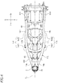
- FIG. 1 is a side view of a motorcycle according to one embodiment.
- FIG. 2 is a side view of a portion of the motorcycle.
- FIG. 3 is a plan view of a portion of the motorcycle.
- FIG. 4 is a plan view of a vehicle body frame.
- FIG. 5 is a perspective view of a left connecting frame and a right connecting frame.
- FIG. 6 is a side view of a fuel tank and a portion of the vehicle body frame.
- FIG. 7 is a side view schematically showing a portion of the motorcycle.
- FIG. 8 is a cross-sectional view taken along line H-H of FIG. 6 .
- FIG. 9 is a plan view of a main frame, a protruding member and a rubber bracket.
- FIG. 10 is a perspective view of the rubber bracket.
- FIG. 11 is an exploded perspective view of a portion of a side cover, a duct part and an air cleaner, and a radiator.
- FIG. 12 is a cross-sectional view taken along line K-K of FIG. 1 , showing the side cover and the duct part.
- FIG. 13 is a side view of the air cleaner and the duct part.
- FIG. 14 is a plan view of the air cleaner and the duct part.
- FIG. 15 is a plan view of the air cleaner and the duct part, with an upper case removed.
- FIG. 16 is a cross-sectional view taken along line M-M of FIG. 15 .
- FIG. 17 is a side view of a vehicle body frame of a conventional motorcycle.
- FIG. 1 is a side view of a motorcycle 1 according to the embodiment.
- the motorcycle 1 includes a vehicle body frame 3 including a head pipe 2 , an engine unit 4 , a handle 5 , a front wheel 6 , a rear wheel 7 , and a seat 8 on which the rider is seated.
- front, rear, left, right, up and down refer to these directions as seen from the rider while assuming that the motorcycle 1 is standing upright on a horizontal surface with no load thereon. Note that “no load” means that there is no rider on the motorcycle 1 and the motorcycle 1 has no fuel.
- front is not limited to the horizontal forward direction, but is inclusive of any inclined direction that is in the range of ⁇ 45° to +45° with respect to the horizontal forward direction, unless specified otherwise.
- rear is not limited to the horizontal rearward direction, but is inclusive of any inclined direction that is in the range of ⁇ 45° to +45° with respect to the horizontal rearward direction.
- left is not limited to the leftward direction in the vehicle width direction, but is inclusive of any inclined direction that is in the range of ⁇ 45° to +45° with respect to that direction.
- right is not limited to the rightward direction in the vehicle width direction, but is inclusive of any inclined direction that is in the range of ⁇ 45° to +45° with respect to that direction.
- the term “up” is not limited to the vertical upward direction, but is inclusive of any inclined direction that is in the range of ⁇ 45° to +45° with respect to the vertical upward direction.
- the term “down” is not limited to the vertical downward direction, but is inclusive of any inclined direction that is in the range of ⁇ 45° to +45° with respect to the vertical downward direction.
- the terms “down” and “downward” generally refer to the relationship of an object and the ground, or the surface on which the vehicle, such as the motorcycle, is resting with its wheels or tires on the ground or surface. In other words, the direction of the ground or surface on which the tires are resting relative to an object on the vehicle is generally down or downward relative to the object on the vehicle.
- a front portion of an object refers to a portion that is forward of the middle of the object in the vehicle front-rear direction, unless specified otherwise.
- a rear portion of an object refers to a portion that is rearward of the middle of the object in the vehicle front-rear direction.
- a steering shaft (not shown) is supported on the head pipe 2 so that the steering shaft can rotate left and right.
- the handle 5 is secured on an upper portion of the steering shaft.
- a front fork 9 is secured on a lower portion of the steering shaft.
- the front wheel 6 including a tire 6 a is supported on a lower portion of the front fork 9 .
- a front fender 10 is placed above the front wheel 6 .
- a rear arm 12 is supported on the vehicle body frame 3 via a pivot shaft 11 so that the rear arm 12 can pivot up and down.
- the rear wheel 7 including a tire 7 a is supported on a rear end portion of the rear arm 12 .
- the engine unit 4 and the rear wheel 7 are linked together via a transmission member 13 such as a chain.
- FIG. 2 is a side view of a portion of the motorcycle 1
- FIG. 3 is a plan view of a portion of the motorcycle 1
- the vehicle body frame 3 includes a left main frame 14 L and a right main frame 14 R each extending rearward from the head pipe 2 .
- the vehicle body frame 3 includes a down frame 15 extending downward from the head pipe 2 .
- the left main frame 14 L is placed leftward of the vehicle center line CL
- the right main frame 14 R is placed rightward of the vehicle center line CL.
- the down frame 15 is placed below the left main frame 14 L and the right main frame 14 R.
- the left main frame 14 L includes a first connecting portion 14 a connected to the head pipe 2 , a first front-rear extending portion 14 b extending rearward from the first connecting portion 14 a , and a first up-down extending portion 14 d extending downward from a lower end 14 c of the first front-rear extending portion 14 b .
- the shapes of the left main frame 14 L and the right main frame 14 R are in left-right symmetry with each other.
- the right main frame 14 R includes a second connecting portion 14 e connected to the head pipe 2 , a second front-rear extending portion 14 f extending rearward from the second connecting portion 14 e , and a second up-down extending portion 14 h extending downward from a lower end 14 g of the second front-rear extending portion 14 f .
- the left main frame 14 L has an upper outline 14 p and a lower outline 14 q , as the vehicle is seen from the side.
- the right main frame 14 R has a similar upper outline 14 p and a similar lower outline 14 q .
- the upper outline 14 p of the left main frame 14 L and the upper outline 14 p of the right main frame 14 R are laid on each other, and the lower outline 14 q of the left main frame 14 L and the lower outline 14 q of the right main frame 14 R are laid on each other.
- the first front-rear extending portion 14 b of the left main frame 14 L includes a first portion 14 b 1 that deviates outward (i.e., leftward) in the vehicle width direction while extending rearward from the head pipe 2 , and a second portion 14 b 2 that deviates inward (i.e., rightward) in the vehicle width direction while extending rearward from the first portion 14 b 1 .
- the second front-rear extending portion 14 f of the right main frame 14 R includes a first portion 14 f 1 that deviates outward (i.e., rightward) in the vehicle width direction while extending rearward from the head pipe 2 , and a second portion 14 f 2 that deviates inward (i.e., leftward) in the vehicle width direction while extending rearward from the first portion 14 f 1 .
- the down frame 15 includes a third connecting portion 15 a connected to the head pipe 2 , and a third up-down extending portion 15 b extending downward from the third connecting portion 15 a .
- the third connecting portion 15 a is located below the first connecting portion 14 a and the second connecting portion 14 e .
- the inclination angle of the down frame 15 with respect to the horizontal line is greater than the inclination angle of the first front-rear extending portion 14 b of the left main frame 14 L with respect to the horizontal line and is greater than the inclination angle of the second front-rear extending portion 14 f of the right main frame 14 R with respect to the horizontal line.
- the left main frame 14 L and the down frame 15 are linked together via a left connecting frame 17 L.
- the front end portion of the left connecting frame 17 L is connected to the down frame 15
- the rear end portion of the left connecting frame 17 L is connected to the first front-rear extending portion 14 b of the left main frame 14 L.
- the right main frame 14 R and the down frame 15 are linked together via a right connecting frame 17 R.
- the front end portion of the right connecting frame 17 R is connected to the down frame 15
- the rear end portion of the right connecting frame 17 R is connected to the second front-rear extending portion 14 f of the right main frame 14 R.
- the dimension of the left connecting frame 17 L in the up-down direction is smaller than the dimension of the left main frame 14 L in the up-down direction.
- the dimension of the right connecting frame 17 R in the up-down direction is smaller than the dimension of the right main frame 14 R in the up-down direction.
- the left connecting frame 17 L is thinner than the left main frame 14 L, and the right connecting frame 17 R is thinner than the right main frame 14 R.
- the left connecting frame 17 L and the right connecting frame 17 R may be separate from each other or may be an integral piece.
- the left connecting frame 17 L and the right connecting frame 17 R are a single U-shaped pipe 17 , as shown in FIG. 5 .
- the pipe 17 is welded to the down frame 15 .
- the left half of the pipe 17 is the left connecting frame 17 L, and the right half thereof is the right connecting frame 17 R.
- the first front-rear extending portion 14 b of the left main frame 14 L and the second front-rear extending portion 14 f of the right main frame 14 R are connected together via a cross frame 18 .
- the cross frame 18 extends in the vehicle width direction.
- the left end portion of the cross frame 18 is connected to the first front-rear extending portion 14 b
- the right end portion thereof is connected to the second front-rear extending portion 14 f .
- the left end portion of the cross frame 18 is connected to the second portion 14 b 2 of the first front-rear extending portion 14 b
- the right end portion of the cross frame 18 is connected to the second portion 14 f 2 of the second front-rear extending portion 14 f .
- the cross frame 18 is shaped so that the dimension thereof in the front-rear direction is larger than the dimension thereof in the up-down direction. Note however that this and the placement of the cross frame 18 are merely illustrative, and embodiments of the present invention are not limited to the illustrated placement of the cross frame 18 .
- the broken line 18 K of FIG. 2 represents a cross section of the cross frame 18 at the center in the vehicle width direction. Note that in the present embodiment, the position of the center of the cross frame 18 in the vehicle width direction coincides with the position of the vehicle center line CL. Note that the vehicle center line CL is a line extending in the vehicle front-rear direction passing through a central axis 2 c of the head pipe 2 as seen from above. As shown in FIG.
- a centroid 18 P of the central cross section 18 K in the vehicle width direction of the cross frame 18 is located within an area that is delimited by an upper extension 17 r obtained by extending rearward an upper outline 17 p of the left connecting frame 17 L, a lower extension 17 s obtained by extending rearward a lower outline 17 q of the left connecting frame 17 L, the upper outline 14 p of the left main frame 14 L and the lower outline 14 q of the left main frame 14 L.
- the centroid 18 P is located within an area that is delimited by the upper extension 17 r obtained by extending rearward the upper outline 17 p of the right connecting frame 17 R, the lower extension 17 s obtained by extending rearward the lower outline 17 q of the right connecting frame 17 R, the upper outline 14 p of the right main frame 14 R and the lower outline 14 q of the right main frame 14 R.
- the cross frame 18 is placed at a position relatively far away from the head pipe 2 .
- Embodiments of the invention are not limited to any one distance between the cross frame 18 and the head pipe 2 , but the distance L 1 between the central axis 2 c of the head pipe 2 and the centroid 18 P of the cross frame 18 is, according to one embodiment, twice or more the dimension L 2 of the head pipe 2 in the central axis direction. In one embodiment, L 1 may be two to three times L 2 .
- a portion where the left connecting frame 17 L and the left main frame 14 L are connected together and a portion where the right connecting frame 17 R and the right main frame 14 R are connected together are placed at positions relatively far away from the head pipe 2 .
- the distance L 3 between the intersection point 17 n between the upper extension 17 r of the left connecting frame 17 L and the central line 14 j of the left main frame 14 L and the central axis 2 c of the head pipe 2 is twice or more the dimension L 2 of the head pipe 2 in the central axis direction. That is, L 3 ⁇ 2 ⁇ L 2 .
- the distance L 3 between the intersection point 17 n between the upper extension 17 r of the right connecting frame 17 R and the central line 14 j of the right main frame 14 R and the central axis 2 c of the head pipe 2 is twice or more the dimension L 2 of the head pipe 2 in the central axis direction. That is, L 3 ⁇ 2 ⁇ L 2 .
- the dimension L 3 is set to a value close to the dimension L 1 .
- L 3 is set to be 0.8 to 1 time L 1 . 0.8 ⁇ L 1 ⁇ L 3 ⁇ 1.0 ⁇ L 1 . Note however that the relationship between L 1 to L 3 described above is illustrative, and embodiments of the invention are not limited to the above relationship.
- the vehicle body frame 3 includes left and right upper seat frames 19 A and 19 C and left and right lower seat frames 19 B and 19 D (see FIG. 3 ) supporting the seat 8 .
- the front end portions of the left and right upper seat frames 19 A and 19 C are connected to the cross frame 18 .
- the upper seat frames 19 A and 19 C extend rearward from the cross frame 18 .
- points 19 a at which the upper seat frames 19 A and 19 C are attached to the cross frame 18 are located above the upper extension 17 r of the left connecting frame 17 L and the upper extension 17 r of the right connecting frame 17 R. Note however that embodiments of the invention are not limited to the illustrated position of the point of attachment 19 a .
- the front end portion of the left lower seat frame 19 B is connected to the first up-down extending portion 14 d of the left main frame 14 L.
- the rear end portion of the left upper seat frame 19 A and the rear end portion of the left lower seat frame 19 B are connected to each other.
- the front end portion of the right upper seat frame 19 C is connected to the second up-down extending portion 14 h of the right main frame 14 R.
- the rear end portion of the right upper seat frame 19 C and the rear end portion of the right lower seat frame 19 D are connected together.
- a rear cross frame 44 and a rear cross frame 45 located rearward of the rear cross frame 44 are connected to the left upper seat frame 19 A and the right upper seat frame 19 C.
- the vehicle body frame 3 includes a left lower frame 16 L that connects together the down frame 15 and the first up-down extending portion 14 d of the left main frame 14 L, and a right lower frame 16 R that connects together the down frame 15 and the second up-down extending portion 14 h of the right main frame 14 R.
- the front end portion of the left lower frame 16 L and the front end portion of the right lower frame 16 R are connected to the lower end portion of the third up-down extending portion 15 b of the down frame 15 .
- the rear end portion of the left lower frame 16 L is connected to the lower end portion of the first up-down extending portion 14 d .
- the rear end portion of the right lower frame 16 R is connected to the lower end portion of the second up-down extending portion 14 h.
- an upper end portion 60 a of a rear cushion unit 60 is supported on the cross frame 18 .
- the upper end portion 60 a of the rear cushion unit 60 is pivotally supported on the central portion of the cross frame 18 in the vehicle width direction.
- reference sign 60 b represents the pivotal point of the upper end portion 60 a of the rear cushion unit 60 .
- Reference sign 60 d represents the lower end portion of the rear cushion unit 60 .
- the pivotal point 60 b is located between the upper extension 17 r obtained by extending rearward the upper outline 17 p of the left connecting frame 17 L and the lower extension 17 s obtained by extending rearward the lower outline 17 q of the left connecting frame 17 L.
- the pivotal point 60 b is located between the upper extension 17 r obtained by extending rearward the upper outline 17 p of the right connecting frame 17 R and the lower extension 17 s obtained by extending rearward the lower outline 17 q of the right connecting frame 17 R, as the vehicle is seen from the side.
- the pivotal point 60 b is placed upward and rearward of the upper outline 14 p of the left main frame 14 L and the right main frame 14 R, as the vehicle is seen from the side, in the present embodiment, but embodiments of the invention are not limited to the illustrated placement of the pivotal point 60 b .
- the rear cushion unit 60 may be a shock absorber or any device configured to absorb shock or cushion a force received from the rear wheel 7 so that the vehicle body frame 3 does not receive the full force of a shock, bump, or jolt received from the rear wheel 7 .
- Embodiments of the present invention include a rear cushion unit 60 embodied in a hydraulic shock absorber, spring-implemented shock absorber, or any other shock absorbing device.
- the engine unit 4 includes a crankcase 20 , a cylinder body 21 , a cylinder head 22 and a cylinder head cover 23 .
- the cylinder body 21 is placed on top of the crankcase 20
- the cylinder head 22 is placed on top of the cylinder body 21
- the cylinder head cover 23 is placed on top of the cylinder head 22 .
- the crank shaft of the internal combustion engine is accommodated inside the crankcase 20 .
- a cylinder that slidably accommodates a piston therein is formed inside the cylinder body 21 .
- An intake port and an exhaust port are formed in the cylinder head 22
- an intake cam and an exhaust cam are accommodated in the cylinder head 22 .
- the cylinder head cover 23 is connected to the upper portion of the cylinder head 22 .
- the engine unit 4 is suspended on the vehicle body frame 3 .
- a portion of the engine unit 4 is supported on the down frame 15 via a bracket 24 .
- Another portion of the engine unit 4 is supported on the lower frames 16 L and 16 R via brackets 25 .
- Another portion of the engine unit 4 is supported on the main frames 14 L and 14 R via brackets 26 .
- the left connecting frame 17 L and the cylinder head cover 23 partially overlap with each other, as the vehicle is seen from the side.
- the right connecting frame 17 R and the cylinder head cover 23 partially overlap with each other, as the vehicle is seen from the side.
- the internal combustion engine of the engine unit 4 is a water-cooled internal combustion engine.
- the motorcycle 1 includes a radiator 27 .
- the radiator 27 serves to radiate heat of the cooling water of the internal combustion engine.
- the radiator 27 is supported on the vehicle body frame 3 .
- the radiator 27 is secured on the down frame 15 .
- the radiator 27 is placed forward of the engine unit 4 .
- the radiator 27 is placed below the head pipe 2 .
- the motorcycle 1 includes a fuel tank 30 .
- Fuel to be supplied to the internal combustion engine of the engine unit 4 is stored in the fuel tank 30 .
- the fuel tank 30 includes a tank body 30 a , and a cap 30 c attached to an oil fill port 30 b in the upper portion of the tank body 30 a .
- Embodiments of the invention are not limited to only the illustrated position of the cap 30 c , but, according to one embodiment, the cap 30 c is placed in the front portion of the tank body 30 a .
- the tank body 30 a includes a left and a right side wall 30 d . Note that the shape of the fuel tank 30 is simplified in FIG. 7 .
- FIG. 8 shows a cross section taken along line H-H of FIG. 6 . Note however that the central portion in the vehicle width direction is not shown.
- the left and right side walls 30 d are each provided with a protruding member 31 extending sideways. While the protruding member 31 is herein formed by a cylindrical member, the present invention is not limited to a cylindrical shape. Although the protruding member 31 may be assembled onto the side wall 30 d via a bolt, or the like, it is herein integral with the side wall 30 d .
- the protruding member 31 and the side wall 30 d are made of a resin and are integral together. As shown in FIG.
- the protruding member 31 is provided in the front portion of the side wall 30 d .
- the protruding member 31 is placed directly below the cap 30 c , as the vehicle is seen from the side. Note however that embodiments of the invention are not limited to any one position of the protruding member 31 .
- rubber brackets 32 are attached to the left main frame 14 L and the right main frame 14 R.
- the rubber brackets 32 are fastened to the left main frame 14 L and the right main frame 14 R via bolts 33 .
- the rubber brackets 32 are attached to the inner surfaces in the vehicle width direction of the left main frame 14 L and the right main frame 14 R.
- the left main frame 14 L and the rubber bracket 32 are laid on each other, as the vehicle is seen from the side.
- the right main frame 14 R and the rubber bracket 32 are laid on each other, as the vehicle is seen from the side.
- the rubber brackets 32 are formed in a concave shape that is open upward. Also, the rubber brackets 32 are open on the inner side thereof in the vehicle width direction.
- the rubber brackets 32 are configured to engage with the protruding members 31 of the fuel tank 30 .
- the protruding members 31 are pushed into the rubber brackets 32 in the downward direction, the protruding members 31 are fitted into the rubber brackets 32 .
- the protruding members 31 can be fitted into the rubber brackets 32 simply by pushing down the fuel tank 30 from above.
- the front portion of the fuel tank 30 is supported on the main frames 14 L and 14 R via the protruding members 31 and the rubber brackets 32 .
- FIG. 8 and FIG. 9 the rubber brackets 32 are configured to engage with the protruding members 31 of the fuel tank 30 .
- the rubber bracket 32 includes a supporting portion 32 a that supports the protruding member 31 , and a pair of, front and rear, barb portions 32 b located above the supporting portion 32 a .
- the front barb portion 32 b bulges rearward while extending upward, and the rear barb portion 32 b bulges forward while extending upward.
- the barb portions 32 b are formed so that the interval therebetween narrows while extending upward. Therefore, once the protruding member 31 is supported on the supporting portion 32 a , the protruding member 31 is unlikely to come off the rubber bracket 32 .
- a bracket 45 is secured on a portion of the fuel tank 30 that is rearward of the middle of the fuel tank 30 in the vehicle front-rear direction.
- the bracket 45 is an example of a fastened portion of the fuel tank 30 .
- the bracket 45 is fastened to the vehicle body frame 3 via a bolt 46 .
- the bracket 45 is fastened to the rear cross frame 44 via the bolt 46 .
- a rear end 30 r of the fuel tank 30 is located rearward of a front end 44 f of the rear cross frame 44 .
- a portion of the fuel tank 30 overlaps with the rear cross frame 44 , as the vehicle is seen from above (see FIG. 3 ).
- the seat 8 is placed over the fuel tank 30 . At least a portion of the seat 8 is supported on the fuel tank 30 .
- the seat 8 includes a main seat 8 A, and a sub-seat 8 B placed forward of the main seat 8 A.
- the front end of the main seat 8 A and the front end of the sub-seat 8 B are located forward of the middle position of the fuel tank 30 in the vehicle front-rear direction.
- a front end 8 f of the sub-seat 8 B is the front end of the seat 8 .
- the front end 8 f of the seat 8 is located forward of the middle position of the fuel tank 30 in the vehicle front-rear direction.
- the front end 8 f of the seat 8 is located forward of a front end 30 f of the fuel tank 30 in the vehicle front-rear direction. Note however that the placement of the seat 8 is illustrative, and embodiments of the invention are not limited to the illustrated placement of the seat.
- An air cleaner 40 is placed forward of the fuel tank 30 .
- the fuel tank 30 is placed near the air cleaner 40 .
- the minimum interval G 1 between the fuel tank 30 and the air cleaner 40 in the vehicle front-rear direction is smaller than the dimension T 1 of the rubber bracket 32 in the vehicle front-rear direction.
- a battery 47 is placed rearward of the fuel tank 30 .
- the fuel tank 30 is placed near the battery 47 .
- the minimum interval G 2 between the fuel tank 30 and the battery 47 in the vehicle front-rear direction is smaller than the dimension T 1 of the rubber bracket 32 in the vehicle front-rear direction.
- the air cleaner 40 is placed rearward of the head pipe 2 .
- the air cleaner 40 includes an upper case 41 , a lower case 42 placed below the upper case 41 , and an air cleaner element 43 provided between the upper case 41 and the lower case 42 .
- the air cleaner 40 is configured so that the air introduced into the upper case 41 is cleaned while passing through the air cleaner element 43 , and the cleaned air is supplied to the lower case 42 .
- An intake pipe 49 provided with a throttle body (not shown), etc., is connected to the lower portion of the lower case 42 .
- the intake pipe 49 connects between the air cleaner 40 and the internal combustion engine of the engine unit 4 .
- the motorcycle 1 includes a left and a right side cover 50 .
- the left and right side covers 50 are placed leftward and rightward of the vehicle center line CL, respectively.
- the left side cover 50 and the right side cover 50 may be placed in left-right symmetry, or left-right asymmetry, with each other with respect to a vertical plane containing the vehicle center line CL.
- the shape of the left side cover 50 and the right side cover 50 may be in left-right symmetry, or left-right asymmetry, with each other with respect to a vertical plane containing the vehicle center line CL.
- the shape of the surface-side portion (in other words, the outer portion in the vehicle width direction) of the left side cover 50 and the right side cover 50 may be in left-right symmetry while the shape of the reverse-side portion (in other words, the inner portion in the vehicle width direction) may be in left-right asymmetry.
- the shape of the left side cover 50 and the right side cover 50 may be in left-right symmetry at least with respect to a duct formation portion 50 d to be described below.
- the left side cover 50 will be described below and the description of the right side cover 50 will be omitted.
- the side cover 50 may be composed of a plurality of parts, it is in the present embodiment an integral large cover to be assembled onto other members, as shown in FIG. 11 .
- the side cover 50 is a single, integral part. As shown in FIG. 1 , a portion of the side cover 50 is placed below the cylinder head cover 23 of the engine unit 4 . A portion of the side cover 50 is placed below the cylinder head 22 of the engine unit 4 .
- the side cover 50 includes a radiator cover portion 50 a placed outward of the radiator 27 in the vehicle width direction, a tank cover portion 50 b placed outward of the fuel tank 30 in the vehicle width direction, and a rearward portion 50 c placed outward of at least a portion of the intake pipe 49 in the vehicle width direction.
- the side cover 50 includes the duct formation portion 50 d placed forward of the tank cover portion 50 b . The duct formation portion 50 d is located above the radiator cover portion 50 a and the rearward portion 50 c.
- embodiments of the invention are not limited to any particular material of the side cover 50 , according to one embodiment, it is made of a resin. Likewise, while embodiments of the invention are not limited to any one method for manufacturing the side cover 50 , according to one embodiment, it is manufactured by injection molding. According to one embodiment, the side cover 50 is an injection-molded part.
- a duct part 51 extending forward in the vehicle front-rear direction from the lower case 42 is formed integrally with the lower case 42 of the air cleaner 40 .
- a pair of, left and right, duct parts 51 are provided.
- the lower case 42 and the duct parts 51 are made of a resin, and are formed integrally together.
- FIG. 12 is a cross-sectional view taken along line K-K of FIG. 1 , showing the side cover 50 and the duct part 51 .
- the duct part 51 is assembled onto the duct formation portion 50 d of the side cover 50 , thereby defining a duct 52 connected to the internal space between the upper case 41 and the air cleaner element 43 in the air cleaner 40 .
- the duct part 51 includes an upper edge 51 a extending in the vehicle front-rear direction, a lower edge 51 b extending in the vehicle front-rear direction and located below the upper edge 51 a , and an inner wall 51 c located between the upper edge 51 a and the lower edge 51 b and depressed inward in the vehicle width direction.
- the duct formation portion 50 d of the side cover 50 includes an upper C-shaped-section portion 90 a and a lower C-shaped-section portion 90 b . Grooves 91 a and 91 b are formed in the C-shaped-section portions 90 a and 90 b , respectively.
- the upper edge 51 a of the duct part 51 is fitted into the groove 91 a
- the lower edge 51 b is fitted into the groove 91 b
- reference sign 92 is a sealant.
- An upper portion 51 d of the duct part 51 and an upper portion 50 d 1 of the duct formation portion 50 d are stacked on each other.
- a lower portion 51 e of the duct part 51 and a lower portion 51 d 2 of the duct formation portion 50 d are stacked on each other.
- the lower edge 51 b of the duct part 51 is located outward of the upper edge 51 a in the vehicle width direction.
- FIG. 13 is a side view of the air cleaner 40 and the duct part 51 .
- an air outlet 52 o is formed at the rear end of the duct 52 .
- the air outlet 52 o is open toward the internal space between the upper case 41 and the air cleaner element 43 of the air cleaner 40 .
- the arrow AF in the figure represents the air flow.
- FIG. 14 is a plan view of a portion of the air cleaner 40 and the duct part 51 .
- FIG. 15 is a plan view of a portion of the air cleaner 40 and the duct part 51 , with the upper case 41 removed.
- FIG. 16 is a cross-sectional view taken alone line M-M of FIG. 15 .
- a holder 53 is fastened to the lower case 42 via a bolt 54 .
- the air cleaner element 43 is placed on the holder 53
- a holder 55 is placed on the air cleaner element 43 .
- the holder 53 and the holder 55 each include a plurality of linear members 57 .
- the holder 53 and the holder 55 are formed in a lattice pattern.
- Air paths 58 through which the air passes, are formed between the linear members 57 .
- a portion of the holder 55 is inserted into the central portion of the holder 53 (see FIG. 16 ).
- the holder 55 is held down by a plate material 56 .
- the holder 55 and the holder 53 are assembled together, as described above, with the air cleaner element 43 sandwiched between the holder 55 and the holder 53 (see FIG. 16 ).
- the air cleaner element 43 is held between the upper case 41 and the lower case 42 .
- the side cover 50 , the duct part 51 and the radiator 27 are assembled together via a bolt 71 .
- the lower portion of the side cover 50 and the lower portion of the radiator 27 are assembled together via a bolt 72 .
- the side cover 50 and the vehicle body frame 3 (not shown in FIG. 11 ) are assembled together via a bolt 75 .
- the bolts 71 , 72 and 75 are fastened from the side.
- a portion of the side cover 50 and a portion of the lower case 42 are laid on each other and are fastened together via a bolt 73 .
- the tank cover portion 50 b of the side cover 50 and the fuel tank 30 (not shown in FIG. 11 ) are fastened together via a bolt 74 .
- the bolt 73 and the bolt 74 are fastened from above.
- bolts 71 to 75 are an example fastener, the fastener is not limited to bolts.
- the fastener may be screws, or the like.
- the centroid 18 P of the cross frame 18 is located within an area that is delimited by the upper extension 17 r obtained by extending rearward the upper outline 17 p of the left connecting frame 17 L, the lower extension 17 s obtained by extending rearward the lower outline 17 q of the left connecting frame 17 L, the upper outline 14 p of the left main frame 14 L and the lower outline 14 q of the left main frame 14 L.
- centroid 18 P is located within an area that is delimited by the upper extension 17 r obtained by extending rearward the upper outline 17 p of the right connecting frame 17 R, the lower extension 17 s obtained by extending rearward the lower outline 17 q of the right connecting frame 17 R, the upper outline 14 p of the right main frame 14 R and the lower outline 14 q of the right main frame 14 R.
- the cross frame 18 is placed as described above, the position of the upper end portion 60 a of the rear cushion unit 60 is kept at a relatively high position, and a distance is ensured between the head pipe 2 and the cross frame 18 .
- the rear cushion unit 60 does not need to be installed in an attitude that is substantially inclined from the vertical line, and the upward force that is received from the road surface by the rear wheel 7 is likely to be absorbed directly by the rear cushion unit 60 .
- a shock is applied onto the head pipe 2 from the front, there is likely to be a shock absorbing effect from the left main frame 14 L and the right main frame 14 R being bent left and right. Therefore, even when running fast on a bad road, it is possible to reduce the amount of energy in the pitching direction from the road surface to be transmitted to the rider and to increase the amount of time over which the tires 6 a and 7 a are in contact with the road surface.
- the distance L 3 between the intersection point 17 n between the upper extension 17 r of the left connecting frame 17 L and the central line 14 j of the left main frame 14 L and the central axis 2 c of the head pipe 2 is 0.8 to 1.0 time the distance L 1 between the central axis 2 c of the head pipe 2 and the centroid 18 P of the cross frame 18 .
- the distance L 3 between the intersection point 17 n between the upper extension 17 r of the right connecting frame 17 R and the central line 14 j of the right main frame 14 R and the central axis 2 c of the head pipe 2 is 0.8 to 1.0 time L 1 .
- L 3 is twice or more L 2 .
- the distance between the head pipe 2 and the connecting portion between the left main frame 14 L and the left connecting frame 17 L is relatively long.
- the distance between the head pipe 2 and the connecting point between the right main frame 14 R and the right connecting frame 17 R is relatively long. Therefore, when a shock is applied onto the head pipe 2 from the front, it is possible to sufficiently realize a shock absorbing effect from the left main frame 14 L and the right main frame 14 R being bent. Therefore, it is possible to sufficiently reduce the amount of energy in the pitching direction from the road surface to be transmitted to the rider.
- the left main frame 14 L and the right main frame 14 R include the first portions 14 b 1 and 14 f 1 that deviate outward in the vehicle width direction while extending rearward from the head pipe 2 , as the vehicle is seen from above, and the second portions 14 b 2 and 14 f 2 that deviate inward in the vehicle width direction while extending rearward from the first portions 14 b 1 and 14 f 1 , as the vehicle is seen from above.
- the first portions 14 b 1 and 14 f 1 are more easily bent than the second portions 14 b 2 and 14 f 2 .
- the first portions 14 b 1 and 14 f 1 are more likely to exert a shock absorbing effect from being bent than the second portions 14 b 2 and 14 f 2 .
- the cross frame 18 is connected to the second portions 14 b 2 and 14 f 2 , and the first portions 14 b 1 and 14 f 1 are not bound by the cross frame 18 . Therefore, it is possible to sufficiently realize a shock absorbing effect, and it is possible to sufficiently reduce the amount of energy in the pitching direction from the road surface to be transmitted to the rider.
- the pivotal point 60 b of the upper end portion 60 a of the rear cushion unit 60 is located within an area between the upper extension 17 r obtained by extending rearward the upper outline 17 p of the left connecting frame 17 L and the lower extension 17 s obtained by extending rearward the lower outline 17 q of the left connecting frame 17 L, as the vehicle is seen from the side.
- the pivotal point 60 b is located within an area between the upper extension 17 r obtained by extending rearward the upper outline 17 p of the right connecting frame 17 R and the lower extension 17 s obtained by extending rearward the lower outline 17 q of the right connecting frame 17 R, as the vehicle is seen from the side.
- the position of the upper end portion 60 a of the rear cushion unit 60 is relatively high. Therefore, the rear cushion unit 60 does not need to be installed in an attitude that is substantially inclined from the vertical line, and the upward force that is received from the road surface by the rear wheel 7 is likely to be absorbed directly by the rear cushion unit 60 . Therefore, it is possible to increase the amount of time over which the tire 7 a is in contact with the road surface.
- the left connecting frame 17 L and the right connecting frame 17 R are located at a relatively high position such that they partially overlap with the cylinder head cover 23 . Since the cross frame 18 is placed so that the centroid 18 P is located within the area described above, the cross frame 18 is located at a preferred position such that the upper end portion 60 a of the rear cushion unit 60 is located at a relatively high position.
- the point of attachment 19 a of the seat frame 19 A is located above the upper extension 17 r of the left connecting frame 17 L and the upper extension 17 r of the right connecting frame 17 R.
- the centroid 18 P is defined as the centroid of the central cross section 18 K in the vehicle width direction of the main frame 18 .
- the centroid of a vertical section that contains the vehicle center line CL of the main frame 18 can be regarded as the centroid 18 P, instead of the centroid of the central cross section 18 K in the vehicle width direction of the main frame 18 .
- the various positional relationships described above with the present motorcycle may hold true for the centroid 18 P so defined.
- a motorcycle has been described in the embodiment described above as an example straddled vehicle.
- a straddled vehicle is not limited to a motorcycle. It may be any other straddled vehicle such as a three-wheeled vehicle and an all terrain vehicle (ATV).
- ATV all terrain vehicle
- the present invention includes any and all preferred embodiments including equivalent elements, modifications, omissions, combinations, adaptations and/or alterations as would be appreciated by those skilled in the art on the basis of the present disclosure.
- the limitations in the claims are to be interpreted broadly based on the language included in the claims and not limited to examples described in the present specification or during the prosecution of the application.
Landscapes
- Engineering & Computer Science (AREA)
- Mechanical Engineering (AREA)
- Automatic Cycles, And Cycles In General (AREA)
Abstract
Description
Claims (10)
Applications Claiming Priority (2)
| Application Number | Priority Date | Filing Date | Title |
|---|---|---|---|
| JP2016-230669 | 2016-11-28 | ||
| JP2016230669A JP2018086907A (en) | 2016-11-28 | 2016-11-28 | Saddle riding vehicle |
Publications (2)
| Publication Number | Publication Date |
|---|---|
| US20180148122A1 US20180148122A1 (en) | 2018-05-31 |
| US10625809B2 true US10625809B2 (en) | 2020-04-21 |
Family
ID=62193462
Family Applications (1)
| Application Number | Title | Priority Date | Filing Date |
|---|---|---|---|
| US15/677,201 Active 2038-01-19 US10625809B2 (en) | 2016-11-28 | 2017-08-15 | Straddled vehicle |
Country Status (2)
| Country | Link |
|---|---|
| US (1) | US10625809B2 (en) |
| JP (1) | JP2018086907A (en) |
Families Citing this family (4)
| Publication number | Priority date | Publication date | Assignee | Title |
|---|---|---|---|---|
| JP6798974B2 (en) * | 2017-12-28 | 2020-12-09 | 本田技研工業株式会社 | Vehicle resin parts |
| JP2020015386A (en) * | 2018-07-24 | 2020-01-30 | ヤマハ発動機株式会社 | Saddle riding type vehicle |
| IT201800010889A1 (en) * | 2018-12-07 | 2020-06-07 | Piaggio & C Spa | MOTORCYCLE FRONT WITH IMPROVED COOLING AND RELATED MOTORCYCLE |
| IT202000005863A1 (en) * | 2020-03-19 | 2021-09-19 | Piaggio & C Spa | RIDING SADDLE VEHICLE WITH EXTENDED TANK. |
Citations (25)
| Publication number | Priority date | Publication date | Assignee | Title |
|---|---|---|---|---|
| US5261504A (en) * | 1990-03-09 | 1993-11-16 | Yamaha Hatsudoki Kabushiki Kaisha | Motorcycle frame construction |
| US6352132B1 (en) * | 1999-09-05 | 2002-03-05 | Honda Giken Kogyo Kabushiki Kaisha | Vehicle having an intake passageway and an exhaust passageway |
| US6695089B2 (en) * | 2000-03-31 | 2004-02-24 | Honda Giken Kogyo Kabushiki Kaisha | Motorcycle frame |
| US7316410B2 (en) * | 2003-09-09 | 2008-01-08 | Honda Motor Co., Ltd. | Frame structure of small vehicle |
| US7360619B2 (en) * | 2003-02-27 | 2008-04-22 | Honda Motor Co., Ltd. | Motorcycle frame structure |
| WO2008059932A1 (en) | 2006-11-15 | 2008-05-22 | Yamaha Hatsudoki Kabushiki Kaisha | Engine with single cylinder or juxtaposed multiple cylinders and saddle ride-type vehicle with the same |
| US7644795B2 (en) * | 2005-06-17 | 2010-01-12 | Kawasaki Jukogyo Kabushiki Kaisha | Vehicle body structure of motorcycle |
| US7694985B2 (en) * | 2005-06-30 | 2010-04-13 | Honda Motor Co., Ltd. | Reinforced motorcycle frame |
| US7699132B2 (en) * | 2006-02-23 | 2010-04-20 | Honda Motor Co., Ltd. | Motorcycle body frame structure |
| US8157041B2 (en) * | 2007-03-22 | 2012-04-17 | Suzuki Kabushiki Kaisha | Intake device for motorcycle |
| US8272656B2 (en) * | 2009-02-02 | 2012-09-25 | Yamaha Hatsudoki Kabushiki Kaisha | Frame structure of a vehicle |
| US8678485B2 (en) * | 2011-12-20 | 2014-03-25 | Honda Motor Co., Ltd. | Hollow welded assembled frame structure |
| US8746389B2 (en) * | 2011-07-26 | 2014-06-10 | Suzuki Motor Corporation | Vehicle body frame |
| US8770332B2 (en) * | 2011-10-24 | 2014-07-08 | Yamaha Hatsudoki Kabushiki Kaisha | Motorcycle and vehicle body frame |
| US9150101B2 (en) * | 2013-06-04 | 2015-10-06 | Suzuki Motor Corporation | Fuel-cell vehicle |
| US9272747B2 (en) * | 2013-07-03 | 2016-03-01 | Kawasaki Jukogyo Kabushiki Kaisha | Body frame of motorcycle and method for manufacturing the body frame |
| US9308958B2 (en) * | 2013-11-15 | 2016-04-12 | Kawasaki Jukogyo Kabushiki Kaisha | Engine support structure in motorcycle |
| US20160177807A1 (en) * | 2014-05-14 | 2016-06-23 | Suzuki Motor Corporation | Engine cooling system for motorcycle |
| US9381969B2 (en) * | 2013-07-31 | 2016-07-05 | Honda Motor Co., Ltd. | Body frame for a saddle-type vehicle, and vehicle including same |
| US20160200391A1 (en) * | 2013-09-11 | 2016-07-14 | Honda Motor Co., Ltd. | Saddle-type vehicle |
| US20160244116A1 (en) * | 2014-09-30 | 2016-08-25 | Honda Motor Co., Ltd. | Saddle-ride type vehicle |
| US9428238B2 (en) * | 2013-09-11 | 2016-08-30 | Honda Motor Co., Ltd. | Body frame structure for saddle type vehicle |
| US20160264206A1 (en) * | 2013-11-07 | 2016-09-15 | Kawasaki Jukogyo Kabushiki Kaisha | Vehicle body frame structure of straddle-type vehicle |
| US20160264205A1 (en) * | 2013-11-07 | 2016-09-15 | Kawasaki Jukogyo Kabushiki Kaisha | Vehicle body frame structure of straddle-type vehicle |
| US20160288858A1 (en) * | 2015-03-31 | 2016-10-06 | Honda Motor Co., Ltd. | Vehicle body frame of saddle-ride-type vehicle |
-
2016
- 2016-11-28 JP JP2016230669A patent/JP2018086907A/en active Pending
-
2017
- 2017-08-15 US US15/677,201 patent/US10625809B2/en active Active
Patent Citations (27)
| Publication number | Priority date | Publication date | Assignee | Title |
|---|---|---|---|---|
| US5261504A (en) * | 1990-03-09 | 1993-11-16 | Yamaha Hatsudoki Kabushiki Kaisha | Motorcycle frame construction |
| US6352132B1 (en) * | 1999-09-05 | 2002-03-05 | Honda Giken Kogyo Kabushiki Kaisha | Vehicle having an intake passageway and an exhaust passageway |
| US6695089B2 (en) * | 2000-03-31 | 2004-02-24 | Honda Giken Kogyo Kabushiki Kaisha | Motorcycle frame |
| US7360619B2 (en) * | 2003-02-27 | 2008-04-22 | Honda Motor Co., Ltd. | Motorcycle frame structure |
| US7316410B2 (en) * | 2003-09-09 | 2008-01-08 | Honda Motor Co., Ltd. | Frame structure of small vehicle |
| US7644795B2 (en) * | 2005-06-17 | 2010-01-12 | Kawasaki Jukogyo Kabushiki Kaisha | Vehicle body structure of motorcycle |
| US7694985B2 (en) * | 2005-06-30 | 2010-04-13 | Honda Motor Co., Ltd. | Reinforced motorcycle frame |
| US7699132B2 (en) * | 2006-02-23 | 2010-04-20 | Honda Motor Co., Ltd. | Motorcycle body frame structure |
| WO2008059932A1 (en) | 2006-11-15 | 2008-05-22 | Yamaha Hatsudoki Kabushiki Kaisha | Engine with single cylinder or juxtaposed multiple cylinders and saddle ride-type vehicle with the same |
| US20090320785A1 (en) | 2006-11-15 | 2009-12-31 | Yamaha Hatsudoki Kabushiki Kaisha | Single-cylinder or in-line multi-cylinder engine and straddle-type vehicle provided with the same |
| US8245672B2 (en) * | 2006-11-15 | 2012-08-21 | Yamaha Hatsudoki Kabushiki Kaisha | Single-cylinder or in-line multi-cylinder engine and straddle-type vehicle provided with the same |
| US8157041B2 (en) * | 2007-03-22 | 2012-04-17 | Suzuki Kabushiki Kaisha | Intake device for motorcycle |
| US8272656B2 (en) * | 2009-02-02 | 2012-09-25 | Yamaha Hatsudoki Kabushiki Kaisha | Frame structure of a vehicle |
| US8746389B2 (en) * | 2011-07-26 | 2014-06-10 | Suzuki Motor Corporation | Vehicle body frame |
| US8770332B2 (en) * | 2011-10-24 | 2014-07-08 | Yamaha Hatsudoki Kabushiki Kaisha | Motorcycle and vehicle body frame |
| US8678485B2 (en) * | 2011-12-20 | 2014-03-25 | Honda Motor Co., Ltd. | Hollow welded assembled frame structure |
| US9150101B2 (en) * | 2013-06-04 | 2015-10-06 | Suzuki Motor Corporation | Fuel-cell vehicle |
| US9272747B2 (en) * | 2013-07-03 | 2016-03-01 | Kawasaki Jukogyo Kabushiki Kaisha | Body frame of motorcycle and method for manufacturing the body frame |
| US9381969B2 (en) * | 2013-07-31 | 2016-07-05 | Honda Motor Co., Ltd. | Body frame for a saddle-type vehicle, and vehicle including same |
| US20160200391A1 (en) * | 2013-09-11 | 2016-07-14 | Honda Motor Co., Ltd. | Saddle-type vehicle |
| US9428238B2 (en) * | 2013-09-11 | 2016-08-30 | Honda Motor Co., Ltd. | Body frame structure for saddle type vehicle |
| US20160264206A1 (en) * | 2013-11-07 | 2016-09-15 | Kawasaki Jukogyo Kabushiki Kaisha | Vehicle body frame structure of straddle-type vehicle |
| US20160264205A1 (en) * | 2013-11-07 | 2016-09-15 | Kawasaki Jukogyo Kabushiki Kaisha | Vehicle body frame structure of straddle-type vehicle |
| US9308958B2 (en) * | 2013-11-15 | 2016-04-12 | Kawasaki Jukogyo Kabushiki Kaisha | Engine support structure in motorcycle |
| US20160177807A1 (en) * | 2014-05-14 | 2016-06-23 | Suzuki Motor Corporation | Engine cooling system for motorcycle |
| US20160244116A1 (en) * | 2014-09-30 | 2016-08-25 | Honda Motor Co., Ltd. | Saddle-ride type vehicle |
| US20160288858A1 (en) * | 2015-03-31 | 2016-10-06 | Honda Motor Co., Ltd. | Vehicle body frame of saddle-ride-type vehicle |
Also Published As
| Publication number | Publication date |
|---|---|
| US20180148122A1 (en) | 2018-05-31 |
| JP2018086907A (en) | 2018-06-07 |
Similar Documents
| Publication | Publication Date | Title |
|---|---|---|
| US10625809B2 (en) | Straddled vehicle | |
| CN102700658B (en) | ride-on vehicle | |
| CN102695645B (en) | Evaporated fuel control device for vehicles that are straddled | |
| US8157041B2 (en) | Intake device for motorcycle | |
| US8061468B2 (en) | Vehicle | |
| US8281889B2 (en) | Seat structure for vehicle and vehicle incorporating same | |
| US20080184954A1 (en) | Vehicle | |
| CA2944812C (en) | Saddle type vehicle with improved boarding | |
| JP2015054606A (en) | Saddle-riding type vehicle | |
| JP6244607B2 (en) | Shroud structure of saddle riding type vehicle | |
| US10202948B2 (en) | Straddled vehicle | |
| US7140329B2 (en) | Vehicle | |
| US10556635B2 (en) | Straddled vehicle | |
| US8256564B2 (en) | Vehicle and vehicle exhaust pipe | |
| EP4385867A1 (en) | Gas tank of straddle-type vehicle with swing engine | |
| JP5324401B2 (en) | Front structure of saddle-ride type vehicle | |
| US7614468B2 (en) | Straddle-type vehicle | |
| US7972047B2 (en) | Headlight unit | |
| WO2021149544A1 (en) | Saddle-type vehicle | |
| ES2294873B2 (en) | FUEL TUBE STRUCTURE FOR VEHICLES. | |
| CN102470908A (en) | motorcycle | |
| CA2549893C (en) | Rough terrain vehicle | |
| US10215139B2 (en) | Straddled vehicle | |
| CN100445158C (en) | vehicle | |
| JP7440551B2 (en) | tank cover |
Legal Events
| Date | Code | Title | Description |
|---|---|---|---|
| AS | Assignment |
Owner name: YAMAHA HATSUDOKI KABUSHIKI KAISHA, JAPAN Free format text: ASSIGNMENT OF ASSIGNORS INTEREST;ASSIGNORS:MURAYAMA, YUKI;SATOH, KATSUTOSHI;MIURA, HIDEKI;REEL/FRAME:043294/0024 Effective date: 20170615 |
|
| STPP | Information on status: patent application and granting procedure in general |
Free format text: NON FINAL ACTION MAILED |
|
| STPP | Information on status: patent application and granting procedure in general |
Free format text: RESPONSE TO NON-FINAL OFFICE ACTION ENTERED AND FORWARDED TO EXAMINER |
|
| STPP | Information on status: patent application and granting procedure in general |
Free format text: FINAL REJECTION MAILED |
|
| STPP | Information on status: patent application and granting procedure in general |
Free format text: DOCKETED NEW CASE - READY FOR EXAMINATION |
|
| STPP | Information on status: patent application and granting procedure in general |
Free format text: NOTICE OF ALLOWANCE MAILED -- APPLICATION RECEIVED IN OFFICE OF PUBLICATIONS |
|
| STCF | Information on status: patent grant |
Free format text: PATENTED CASE |
|
| MAFP | Maintenance fee payment |
Free format text: PAYMENT OF MAINTENANCE FEE, 4TH YEAR, LARGE ENTITY (ORIGINAL EVENT CODE: M1551); ENTITY STATUS OF PATENT OWNER: LARGE ENTITY Year of fee payment: 4 |