US10625697B2 - Multi-purpose brush guard, cabin protector, and tailgate extender accessory - Google Patents
Multi-purpose brush guard, cabin protector, and tailgate extender accessory Download PDFInfo
- Publication number
- US10625697B2 US10625697B2 US15/875,011 US201815875011A US10625697B2 US 10625697 B2 US10625697 B2 US 10625697B2 US 201815875011 A US201815875011 A US 201815875011A US 10625697 B2 US10625697 B2 US 10625697B2
- Authority
- US
- United States
- Prior art keywords
- mounting structure
- vehicle
- purpose accessory
- assembly according
- coupled
- Prior art date
- Legal status (The legal status is an assumption and is not a legal conclusion. Google has not performed a legal analysis and makes no representation as to the accuracy of the status listed.)
- Expired - Fee Related, expires
Links
Images


Classifications
-
- B—PERFORMING OPERATIONS; TRANSPORTING
- B60—VEHICLES IN GENERAL
- B60R—VEHICLES, VEHICLE FITTINGS, OR VEHICLE PARTS, NOT OTHERWISE PROVIDED FOR
- B60R19/00—Wheel guards; Radiator guards, e.g. grilles; Obstruction removers; Fittings damping bouncing force in collisions
- B60R19/02—Bumpers, i.e. impact receiving or absorbing members for protecting vehicles or fending off blows from other vehicles or objects
- B60R19/48—Bumpers, i.e. impact receiving or absorbing members for protecting vehicles or fending off blows from other vehicles or objects combined with, or convertible into, other devices or objects, e.g. bumpers combined with road brushes, bumpers convertible into beds
-
- B—PERFORMING OPERATIONS; TRANSPORTING
- B60—VEHICLES IN GENERAL
- B60R—VEHICLES, VEHICLE FITTINGS, OR VEHICLE PARTS, NOT OTHERWISE PROVIDED FOR
- B60R19/00—Wheel guards; Radiator guards, e.g. grilles; Obstruction removers; Fittings damping bouncing force in collisions
- B60R19/52—Radiator or grille guards ; Radiator grilles
-
- B—PERFORMING OPERATIONS; TRANSPORTING
- B62—LAND VEHICLES FOR TRAVELLING OTHERWISE THAN ON RAILS
- B62D—MOTOR VEHICLES; TRAILERS
- B62D33/00—Superstructures for load-carrying vehicles
- B62D33/02—Platforms; Open load compartments
- B62D33/0207—Connections of movable or detachable racks or stanchions to platforms
-
- B—PERFORMING OPERATIONS; TRANSPORTING
- B60—VEHICLES IN GENERAL
- B60R—VEHICLES, VEHICLE FITTINGS, OR VEHICLE PARTS, NOT OTHERWISE PROVIDED FOR
- B60R19/00—Wheel guards; Radiator guards, e.g. grilles; Obstruction removers; Fittings damping bouncing force in collisions
- B60R19/52—Radiator or grille guards ; Radiator grilles
- B60R2019/522—Bull bars
-
- B—PERFORMING OPERATIONS; TRANSPORTING
- B62—LAND VEHICLES FOR TRAVELLING OTHERWISE THAN ON RAILS
- B62D—MOTOR VEHICLES; TRAILERS
- B62D33/00—Superstructures for load-carrying vehicles
- B62D33/02—Platforms; Open load compartments
- B62D33/023—Sideboard or tailgate structures
- B62D33/027—Sideboard or tailgate structures movable
- B62D33/0273—Movable tailboards for vehicles comprising non-movable sideboards, e.g. pick-up trucks
Definitions
- the present disclosure generally relates to an interchangeable vehicle accessory, and more particularly, to a multi-purpose accessory removably attachable to serve as a brush guard, a cabin protector, and a tailgate extender for a vehicle.
- the present teachings provide a modular system with a multi-purpose accessory configured to selectively operate as a brush guard, a cabin protector, and a tailgate extender for a vehicle.
- the system includes a first mounting structure connected to a front frame of the vehicle.
- a second mounting structure is connected to a cabin portion of the vehicle, and a third mounting structure connected to a tailgate of the vehicle.
- a multi-purpose accessory is provided including a main body portion and at least one attachment member extending from the main body portion.
- the attachment member is configured to alternately be received by the first mounting structure, wherein the multi-purpose accessory serves as a brush guard; the second mounting structure, wherein the multi-purpose accessory serves as a cabin protector; and the third mounting structure, wherein the multi-purpose accessory serves as a tailgate extender.
- the present teachings provide a vehicle assembly with a multi-purpose accessory configured to selectively operate as a brush guard, a cabin protector, and a tailgate extender for the vehicle.
- the assembly includes a front frame comprising a first mounting structure.
- a passenger cabin is provided, comprising a second mounting structure.
- the vehicle further includes a cargo bed comprising a third mounting structure.
- a multi-purpose accessory is provided, including a main body portion and at least one attachment member extending from the main body portion. The attachment member is configured to alternately be received by the first mounting structure to serve as a brush guard; the second mounting structure to serve as a cabin protector; and the third mounting structure to serve as a tailgate extender.
- the present teachings provide a utility vehicle with a multi-purpose accessory configured to selectively operate as a brush guard, a cabin protector, and a tailgate extender for the utility vehicle.
- the utility vehicle includes a front frame with a first mounting structure coupled to the front frame; a passenger cabin with a second mounting structure coupled to the passenger cabin; and a cargo bed defined by a floor, a forward wall, two side walls, and a movable tailgate having an open position and a closed position.
- a third mounting structure is coupled to the tailgate.
- the multi-purpose accessory includes a main body portion and two wing portions. Each wing portion is hingedly coupled to first and second opposing ends of the main body portion. At least one attachment member is provided extending from the main body portion and configured to alternately be received by the first mounting structure to serve as a brush guard; the second mounting structure to serve as a cabin protector; and the third mounting structure to serve as a tailgate extender.
- FIG. 1 is a front perspective view of a pickup truck having an exemplary multi-purpose accessory coupled to a front portion of the pickup truck, configured to serve as a brush guard;
- FIG. 2 is a front plan view of an exemplary multi-purpose accessory according to the present teachings
- FIG. 3 is a rear perspective view of the pickup truck of FIG. 1 having the exemplary multi-purpose accessory coupled to a rear passenger portion of the pickup truck, configured to serve as a cabin protector;
- FIG. 4 is a rear perspective view of the pickup truck of FIG. 1 having the exemplary multi-purpose accessory coupled adjacent to a movable tailgate of the pickup truck, configured to serve as a tailgate extender;
- FIG. 5 is a side perspective view of the pickup truck of FIG. 1 illustrating various different mounting structures
- FIG. 6A is a side perspective view of the pickup truck of FIG. 5 , illustrating the multi-purpose accessory coupled to the movable tailgate of the pickup truck, configured to serve as a tailgate extender;
- FIG. 6B is a side perspective view of the pickup truck of FIG. 5 , illustrating the multi-purpose accessory coupled to a rear deck posts of the pickup truck and in a first position, configured to serve as a tailgate extender;
- FIG. 6C is a side perspective view of the pickup truck of FIG. 5 , illustrating the multi-purpose accessory coupled to the rear deck posts of the pickup truck and in a second position, configured in a storage position within the cargo bed of the pickup truck;
- FIG. 7 is detailed view of one of the mounting structures useful for a cabin protector
- FIG. 8 is a detailed view of one of the mounting structures useful for a brush guard
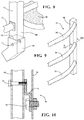
- FIG. 9 is a detailed view of a side wing portion of the multi-purpose accessory that will be coupled to a rear deck post of the pickup truck.
- FIG. 10 is a cross-sectional detailed view of one of the mounting structures configured to couple the side wing portions to the rear deck post.
- the present technology generally provides a modular system with one multi-purpose accessory that is configured to selectively fulfill multiple different roles, including interchangeably functioning as a brush guard, a cabin protector, and a tailgate extender.
- various mounting structures are provided on different areas of the vehicle configured to couple the multi-purpose accessory to the vehicle for its desired use.
- Brush guards also known as grille guards, are commonly mounted to a front portion of a vehicle in order to protect the headlamps and grille portion of the vehicle from direct contact with brush or other obstacles/materials when the vehicle is used in an off-road environment. Brush guards may also provide the same protection for everyday use, for example, by protecting the grille and headlamps from minor accidents or contact with another vehicle or obstacle, such as parking poles and guides.
- Passenger cabin protectors are commonly mounted adjacent a rear portion of a passenger cabin compartment of a utility vehicle, such as a pickup truck, in order to protect cargo from contacting the passenger cabin compartment.
- a cabin protector may protect a rear window of the passenger compartment during the loading of an all-terrain vehicle (ATV), motor cycle, or the like, into a cargo area of the vehicle.
- ATV all-terrain vehicle
- the cab protector may also protect the passenger cabin from shifting cargo during sudden stops, and the like.
- Tailgate extenders or truck bed extenders, are commonly mounted adjacent an end region of a truck bed, or cargo area, and may define a perimeter for extending a length dimension of the truck bed or cargo area in order to provide increased storage capacity for bulky items.
- the tailgate of the vehicle is provided in an open state configuration, which is generally horizontal and level with the truck bed, allowing the tailgate to function as the floor portion of the extended cargo area.
- FIG. 1 is a front perspective view of an exemplary vehicle, a pickup truck 20 , having one non-limiting example of a multi-purpose accessory 22 coupled to a front portion 24 of the pickup truck 20 .
- FIG. 1 illustrates one configuration with the multi-purpose accessory 22 functioning in a brush guard capacity. As discussed above, this configuration may be particularly useful in off-road driving to prevent or minimize damage to the front portion 24 of the vehicle 20 .
- the placement of the multi-purpose accessory 22 in this configuration may also serve as a default position, for example, when there is no current need to protect the passenger cabin 26 area or to extend the rear cargo carrying area 28 .
- FIG. 2 is a front plan view of an exemplary multi-purpose accessory 22 .
- the multi-purpose accessory 22 may include a main body portion 30 and one or more optional wing portions 32 coupled to opposing sides 34 of the main body portion 30 .
- the main body portion 30 may be defined by a plurality of support members 36 coupled to the opposing ends, or sides 34 , of the main body portion 30 .
- the support members 36 may be hollow tubular or square shaped members, with their shape, size, and material selection based on required strength needs or aesthetic preferences.
- the multi-purpose accessory 22 may be coated or painted as desired.
- FIG. 2 illustrates a plurality of tubular support members 36 arranged in a horizontal manner
- the support members 36 may also be vertically aligned, or angled, or provided in any number of different shapes that still ultimately provide for the intended function of the multi-purpose accessory 22 .
- An optional mesh portion 38 may also be provided, attached or coupled to the main body portion 30 .
- the multi-purpose accessory 22 may be a single monolithic component that includes the main body portion 30 as well as any optional side or wing portions 32 .
- the side wing portions 32 may be static or movable with respect to the main body portion 30 .
- the side wing portions 32 are separate components that may be removably coupled to the ends or sides 34 of the main body portion 30 with one or more mechanical fastener (not specifically shown).
- different sized or shaped wing portions 32 may be used in an interchangeable manner.
- the wing portions 32 may be curved to follow a profile of the front vehicle.
- the wing portions 32 may be rotatably coupled to the opposing ends 34 of the main body portion 22 .
- one or more wing portion 32 may be rotatable from 0 to about 45 degrees with respect to a plane defined by the main body portion 30 .
- the wing portion 32 may be better aligned with a front profile or front portion 24 of the vehicle 20 .
- the one or more wing portion 32 may be rotatable from 0 to about 180 degrees with respect to a plane defined by the main body portion 30 , such that the wing portion 32 may be rotated substantially flush with the main body portion 30 , thereby occupying less linear space, which may be particularly preferred for storage purposes.
- the multi-purpose accessory may also be provided with one or more attachment member 40 extending from a lower portion 42 of the main body portion 30 .
- the attachment member 40 may simply be a tubular member or support member that removably couples to a receiving member or mounting structure, such as a bracket located on the vehicle, as discussed in more detail below.
- the main body portion 30 of the multi-purpose accessory 22 may essentially be aligned with the a grille portion of the vehicle 20
- the wing portions 32 may be aligned with the headlamps 41 , fog lamps, or other areas of the front portion 24 of the pickup truck 20 that may require protection.
- the wing portions 32 may be angled with respect to the main body portion 30 to match with a profile of the front of the vehicle 20 .
- the coupling can be made with a removable mechanical fastener, such as a bolt and locking cotter pin assembly.
- a removable mechanical fastener such as a bolt and locking cotter pin assembly.
- the mounting structures 44 may extend through apertures defined in the front bumper 46 and be coupled directly to a front frame portion of the vehicle 20 .
- FIG. 3 is a rear perspective view of the pickup truck of FIG. 1 having the exemplary multi-purpose accessory 22 coupled to a rear of the passenger cabin portion 26 of the truck.
- FIG. 3 illustrates on configuration with the multi-purpose accessory 22 configured to serve as a cabin protector, or cab protector.
- the mounting bracket structures 48 may be coupled to a deck header portion 52 of a cargo bed area 50 of the pickup truck 20 .
- the coupling can be made with a removable mechanical fastener, such as a bolt and locking cotter pin assembly.
- FIG. 4 is a rear perspective view of the pickup truck 20 of FIG. 1 having the exemplary multi-purpose accessory coupled to a movable tailgate 54 of the pickup truck 20 .
- FIG. 4 illustrates one configuration with the multi-purpose accessory 22 functioning as a tailgate extender.
- the vehicle tailgate 54 may include an inner wall 56 and an outer wall 58 made of sheet metal, a plastic material, a composite material, or the like.
- the tailgate 54 may be provided with a substantially upright position, in which the inner wall 56 forms a part of the cargo bed area 50 of the pickup truck 20 .
- the inner wall 56 and the outer wall 58 may cooperate to define the tailgate 54 , which may include one or more support members or reinforcements beams disposed therein (not shown).
- the tailgate 54 may have a drop down position, as shown in FIGS. 4 and 5 . When in this position, the inner wall 56 and the outer wall 58 are substantially parallel with the floor and the ground.
- the mounting bracket structures 55 may be coupled to the inner wall 56 of the tailgate 54 , and may be further coupled to the one or more support or frame components optionally disposed therein. Similar to that discussed above, the coupling of the attachment members 40 of the multi-purpose accessory 22 to the mounting bracket structures 55 of the tailgate 54 can be made with a removable mechanical fastener, such as a bolt and locking cotter pin assembly.
- FIG. 5 a side perspective view of the pickup truck of FIG. 1 , and generally illustrates the various different mounting bracket structures 48 , 55 useful with the multi-purpose accessory of the present technology when functioning as a cab protector or tailgate extender.
- all or some of the mounting bracket structures 44 , 48 , 55 may be of similar design and otherwise functionally equivalent, such that the multi-purpose accessory 22 is easily interchangeable between all positions.
- the multi-purpose accessory 22 and accompanying mounting structures and brackets may be provided with the vehicle 20 as OEM components, or can be added to the vehicle 22 as aftermarket products.
- FIG. 5 illustrates one exemplary cargo bed area 50 , which may be defined by a floor portion 60 , a forward wall 62 adjacent a rear portion the passenger cabin 26 , two opposing side walls 64 , and a movable tailgate 54 that is operable to be in at least an open position and a closed position.
- FIG. 6A is a side perspective view of the pickup truck of FIG. 5 , illustrating the multi-purpose accessory 22 coupled to brackets 55 attached to the inner wall 56 of the movable tailgate 54 of the pickup truck in an open position.
- FIG. 6A is similar to the configuration shown in FIG. 4 with the multi-purpose accessory 22 functioning as a tailgate extender.
- the multi-purpose accessory may be coupled to the side portions of the cargo bed area 50 , and in particular, may be removably coupled to the rear deck posts 66 of the cargo bed 50 .
- the rear deck posts 66 are ultimately coupled to a rear portion the frame of the pickup truck 20 , and provide a strong reinforcement connection.
- FIG. 6B is a side perspective view of the pickup truck of FIG. 5 , illustrating the multi-purpose accessory coupled to the rear deck posts 66 of the pickup truck 20 and in a first position, configured to serve as a tailgate extender.
- the ends 68 of the respective wing portions 32 of the multi-purpose accessory 22 may be provided with an attachment mechanism for connection a mounting structure 70 coupled with the respective rear deck posts 66 .
- FIG. 6C is a side perspective view of the pickup truck of FIG. 5 , illustrating the multi-purpose accessory 22 coupled to the rear deck posts 66 of the pickup truck and in a second position, configured in a storage position within the cargo bed of the pickup truck 20 . Although shown in the open position for clarity, when the multi-purpose accessory 22 is in the second position as shown in FIG.
- the tailgate 54 can be raised, in its closed position.
- the multi-purpose accessory 22 is rotatably coupled to the respective rear deck posts 66 such that the multi-purpose accessory 22 can rotate between the positions as shown in FIGS. 6B and 6C .
- FIGS. 7-10 are provided to illustrate various details of the mounting structures and mounting brackets useful with the multi-purpose accessory 22 . It should be understood that these structures and brackets are provided as exemplary designs, and various modifications may be made as desired or required for different end uses.
- FIG. 7 is detailed view of one of the mounting structures 48 useful for the multi-purpose accessory 22 functioning as a cabin protector.
- the mounting structure 48 may be a simple bracket 48 coupled to the deck header 52 , and the multi-purpose accessory 22 is coupled to the bracket 48 with a locking pin 72 .
- the mounting structures 44 , 48 , 55 may be designed for use with removable fasteners or quick connect type coupling mechanisms.
- a cotter pin or locking pin 72 may be used that slidably engages a pair of co-aligned apertures in the bracket 48 .
- the locking pin 72 may be provided with a suitable handle or gripping portion for a user to grasp when moving the locking pin 72 , as well as any necessary biasing member, such as a coil spring, that may be provided for urging a locking pin shaft toward a locked position.
- a suitable handle or gripping portion for a user to grasp when moving the locking pin 72
- any necessary biasing member such as a coil spring
- FIG. 8 is a detailed view of one of the mounting structures 44 useful for the multi-purpose accessory 22 functioning as a brush guard.
- the attachment members 40 are received into an aperture 45 defined in the mounting bracket 44 that is ultimately coupled to the front frame.
- the mounting structure 44 may extend down in front of and under the front bumper 46 for coupling with the vehicle frame.
- the mounting structure 44 may extend through the front bumper and connect directly to the vehicle frame.
- the mounting structure for the brush guard feature may be a bracket, similar to that shown in FIG. 7 , coupled to the frame through the front bumper 46 .
- FIG. 9 is a detailed view of one of the side wing portions 32 of the multi-purpose accessory 22 that may be coupled to a rear deck post 66 of the pickup truck for the multi-purpose accessory 22 to function as a tailgate extender.
- FIG. 10 is a cross-sectional detailed view of one of the mounting structures 70 configured to couple the side wing portions 32 to the rear deck post 66 .
- the exemplary mounting structure may include a shaped bracket 74 with two locking pins 72 , or equivalent fasteners, such that the multi-purpose accessory 22 can be rotated between the two positions as shown in FIGS. 6B and 6C .
- the various mounting structures 44 , 48 , 55 may be permanently affixed to their respective locations on the vehicle.
- one or more of the mounting structures 44 , 48 , 55 may be removably coupled to the vehicle 20 , and in other aspects, may even be retractable within portions of the vehicle such that they are stored when not in use, and do not otherwise interfere with the use of the vehicle for other purposes.
- the phrase at least one of A, B, and C should be construed to mean a logical (A or B or C), using a non-exclusive logical “or.” It should be understood that the various steps within a method may be executed in different order without altering the principles of the present disclosure. Disclosure of ranges includes disclosure of all ranges and subdivided ranges within the entire range, including the endpoints.
- the terms “comprise” and “include” and their variants are intended to be non-limiting, such that recitation of items in succession or a list is not to the exclusion of other like items that may also be useful in the devices and methods of this technology.
- the terms “can” and “may” and their variants are intended to be non-limiting, such that recitation that an embodiment can or may comprise certain elements or features does not exclude other embodiments of the present technology that do not contain those elements or features.
Landscapes
- Engineering & Computer Science (AREA)
- Mechanical Engineering (AREA)
- Chemical & Material Sciences (AREA)
- Combustion & Propulsion (AREA)
- Transportation (AREA)
- Body Structure For Vehicles (AREA)
Abstract
Description
Claims (13)
Priority Applications (1)
| Application Number | Priority Date | Filing Date | Title |
|---|---|---|---|
| US15/875,011 US10625697B2 (en) | 2018-01-19 | 2018-01-19 | Multi-purpose brush guard, cabin protector, and tailgate extender accessory |
Applications Claiming Priority (1)
| Application Number | Priority Date | Filing Date | Title |
|---|---|---|---|
| US15/875,011 US10625697B2 (en) | 2018-01-19 | 2018-01-19 | Multi-purpose brush guard, cabin protector, and tailgate extender accessory |
Publications (2)
| Publication Number | Publication Date |
|---|---|
| US20190225172A1 US20190225172A1 (en) | 2019-07-25 |
| US10625697B2 true US10625697B2 (en) | 2020-04-21 |
Family
ID=67298035
Family Applications (1)
| Application Number | Title | Priority Date | Filing Date |
|---|---|---|---|
| US15/875,011 Expired - Fee Related US10625697B2 (en) | 2018-01-19 | 2018-01-19 | Multi-purpose brush guard, cabin protector, and tailgate extender accessory |
Country Status (1)
| Country | Link |
|---|---|
| US (1) | US10625697B2 (en) |
Cited By (1)
| Publication number | Priority date | Publication date | Assignee | Title |
|---|---|---|---|---|
| US20230174009A1 (en) * | 2020-05-01 | 2023-06-08 | PeK Automotive d.o.o. | Vehicle protection device |
Families Citing this family (1)
| Publication number | Priority date | Publication date | Assignee | Title |
|---|---|---|---|---|
| EP4563410A1 (en) * | 2023-11-30 | 2025-06-04 | MAGNA STEYR Fahrzeugtechnik GmbH & Co KG | Motor vehicle with roll bar |
Citations (34)
| Publication number | Priority date | Publication date | Assignee | Title |
|---|---|---|---|---|
| US2396652A (en) * | 1942-01-27 | 1946-03-19 | Wall Wire Products Company | Brush guard and method of making same |
| US4099760A (en) * | 1977-05-05 | 1978-07-11 | Mascotte Lawrence L | Grill and brush guard and utility rack for a vehicle |
| US5326142A (en) * | 1993-08-31 | 1994-07-05 | Ford Motor Company | Truck with brush/grill guard, slanted tubular bumper, rally bar and rally bar lights |
| US5468038A (en) * | 1994-09-06 | 1995-11-21 | Sauri; Gregory M. | Multiple configuration tailgate extender |
| US5775759A (en) * | 1996-09-24 | 1998-07-07 | Cummins; Andrew J. | Vehicle bed extender |
| USD396678S (en) * | 1996-10-08 | 1998-08-04 | Leo Shklyaver | Push bumper with side guards for mounting to a bumper of a car |
| US5816638A (en) * | 1997-04-10 | 1998-10-06 | Pool, Iii; William Bryan | Pickup truck bed extender, ramp and tailgate |
| US5900199A (en) * | 1997-11-21 | 1999-05-04 | Algonquin Automotive | Process for making a vehicle grille guard |
| US6227593B1 (en) * | 1998-02-06 | 2001-05-08 | Richard K. De Valcourt | Truck bed extender/ramp |
| US6231093B1 (en) * | 1999-02-02 | 2001-05-15 | Ron D. Storer | Push bar mounting system |
| US6283525B1 (en) | 2000-10-24 | 2001-09-04 | Charles H. Morse | Bed extender apparatus for a pickup truck |
| US6447032B1 (en) * | 2000-09-07 | 2002-09-10 | Raymond L. Howell, Sr. | Tote and brush guard attachment |
| US6626478B1 (en) * | 2002-11-06 | 2003-09-30 | David J. Minton | Tailgate extender |
| US20040160050A1 (en) * | 2003-02-18 | 2004-08-19 | Strong Russell W. | External protection system for a vehicle |
| US20060061114A1 (en) * | 2004-09-23 | 2006-03-23 | Horst Leitner | Vehicle cargo bed extender |
| US7121596B2 (en) | 2004-08-02 | 2006-10-17 | Robert Rood | Clip-on brush guard |
| US20070080548A1 (en) * | 2005-10-11 | 2007-04-12 | Joseph Rowdy L | Moveable guard assembly for all terrain vehicle |
| US7261346B1 (en) * | 2005-06-06 | 2007-08-28 | Grant Kubesh | Truck guard assembly |
| US20080111390A1 (en) * | 2006-10-27 | 2008-05-15 | Anthony Smith | Vehicle cargo tailgate enclosure |
| USD572180S1 (en) * | 2007-08-03 | 2008-07-01 | Xtreme Metal Fab., Inc. | Vehicle brush guard |
| US20080231067A1 (en) * | 2005-02-24 | 2008-09-25 | Nagle Rick A | Retractable Tailgate Barrier and Accessory Systems |
| US20080284190A1 (en) * | 1996-05-21 | 2008-11-20 | American Moto Products, Inc. | Vehicle cargo bed extender |
| US7469958B2 (en) | 2006-08-21 | 2008-12-30 | Hastings Daniel K | Multiple use vehicle accessory |
| US7736105B2 (en) | 2007-11-14 | 2010-06-15 | Chad James Landry | Pickup truck window, bed, and cab protector |
| US20110006553A1 (en) * | 2009-07-07 | 2011-01-13 | Warn Industries, Inc. | Winch Carrier and Grille Guard Mounting System |
| US8075037B2 (en) | 2009-09-29 | 2011-12-13 | Toyota Motor Engineering & Manufacturing North America, Inc. | Vehicle rear end assemblies with storage assemblies |
| US20130049384A1 (en) * | 2011-08-31 | 2013-02-28 | Peter Kekich, Jr. | Push bumper and mounting system |
| US8757694B1 (en) * | 2012-03-15 | 2014-06-24 | Kevin Arlyn Kuhnle | Collapsible tailgate extension |
| US8801058B2 (en) | 2012-01-19 | 2014-08-12 | Overkill Motorsports Inc. | Adjustable modular automotive grille guard assembly |
| US20150021937A1 (en) * | 2013-07-16 | 2015-01-22 | Curt Manufacturing, Llc | Grill Guard With Integrated LED Bar |
| US8998291B1 (en) * | 2013-12-31 | 2015-04-07 | Joseph P. Addis | Vehicle attachable carrier device |
| US20160325700A1 (en) * | 2015-05-07 | 2016-11-10 | Ryde Industries, LLC | Front Bumper for UTV |
| US20170136972A1 (en) | 2013-04-10 | 2017-05-18 | Excel Concepts | Quick Release Grill Guard and Associated Systems and Methods |
| US20170282979A1 (en) * | 2015-12-04 | 2017-10-05 | Nicholas J. Singer | Mega elongator |
-
2018
- 2018-01-19 US US15/875,011 patent/US10625697B2/en not_active Expired - Fee Related
Patent Citations (35)
| Publication number | Priority date | Publication date | Assignee | Title |
|---|---|---|---|---|
| US2396652A (en) * | 1942-01-27 | 1946-03-19 | Wall Wire Products Company | Brush guard and method of making same |
| US4099760A (en) * | 1977-05-05 | 1978-07-11 | Mascotte Lawrence L | Grill and brush guard and utility rack for a vehicle |
| US5326142A (en) * | 1993-08-31 | 1994-07-05 | Ford Motor Company | Truck with brush/grill guard, slanted tubular bumper, rally bar and rally bar lights |
| US5468038A (en) * | 1994-09-06 | 1995-11-21 | Sauri; Gregory M. | Multiple configuration tailgate extender |
| US20080284190A1 (en) * | 1996-05-21 | 2008-11-20 | American Moto Products, Inc. | Vehicle cargo bed extender |
| US5775759A (en) * | 1996-09-24 | 1998-07-07 | Cummins; Andrew J. | Vehicle bed extender |
| USD396678S (en) * | 1996-10-08 | 1998-08-04 | Leo Shklyaver | Push bumper with side guards for mounting to a bumper of a car |
| US5816638A (en) * | 1997-04-10 | 1998-10-06 | Pool, Iii; William Bryan | Pickup truck bed extender, ramp and tailgate |
| US5900199A (en) * | 1997-11-21 | 1999-05-04 | Algonquin Automotive | Process for making a vehicle grille guard |
| US6227593B1 (en) * | 1998-02-06 | 2001-05-08 | Richard K. De Valcourt | Truck bed extender/ramp |
| US6231093B1 (en) * | 1999-02-02 | 2001-05-15 | Ron D. Storer | Push bar mounting system |
| US6447032B1 (en) * | 2000-09-07 | 2002-09-10 | Raymond L. Howell, Sr. | Tote and brush guard attachment |
| US6283525B1 (en) | 2000-10-24 | 2001-09-04 | Charles H. Morse | Bed extender apparatus for a pickup truck |
| US6626478B1 (en) * | 2002-11-06 | 2003-09-30 | David J. Minton | Tailgate extender |
| US20040160050A1 (en) * | 2003-02-18 | 2004-08-19 | Strong Russell W. | External protection system for a vehicle |
| US7121596B2 (en) | 2004-08-02 | 2006-10-17 | Robert Rood | Clip-on brush guard |
| US20060061114A1 (en) * | 2004-09-23 | 2006-03-23 | Horst Leitner | Vehicle cargo bed extender |
| US20080231067A1 (en) * | 2005-02-24 | 2008-09-25 | Nagle Rick A | Retractable Tailgate Barrier and Accessory Systems |
| US7261346B1 (en) * | 2005-06-06 | 2007-08-28 | Grant Kubesh | Truck guard assembly |
| US20070080548A1 (en) * | 2005-10-11 | 2007-04-12 | Joseph Rowdy L | Moveable guard assembly for all terrain vehicle |
| US7469958B2 (en) | 2006-08-21 | 2008-12-30 | Hastings Daniel K | Multiple use vehicle accessory |
| US20170327159A1 (en) | 2006-10-27 | 2017-11-16 | Lund Motion Products, Inc. | Vehicle cargo tailgate enclosure |
| US20080111390A1 (en) * | 2006-10-27 | 2008-05-15 | Anthony Smith | Vehicle cargo tailgate enclosure |
| USD572180S1 (en) * | 2007-08-03 | 2008-07-01 | Xtreme Metal Fab., Inc. | Vehicle brush guard |
| US7736105B2 (en) | 2007-11-14 | 2010-06-15 | Chad James Landry | Pickup truck window, bed, and cab protector |
| US20110006553A1 (en) * | 2009-07-07 | 2011-01-13 | Warn Industries, Inc. | Winch Carrier and Grille Guard Mounting System |
| US8075037B2 (en) | 2009-09-29 | 2011-12-13 | Toyota Motor Engineering & Manufacturing North America, Inc. | Vehicle rear end assemblies with storage assemblies |
| US20130049384A1 (en) * | 2011-08-31 | 2013-02-28 | Peter Kekich, Jr. | Push bumper and mounting system |
| US8801058B2 (en) | 2012-01-19 | 2014-08-12 | Overkill Motorsports Inc. | Adjustable modular automotive grille guard assembly |
| US8757694B1 (en) * | 2012-03-15 | 2014-06-24 | Kevin Arlyn Kuhnle | Collapsible tailgate extension |
| US20170136972A1 (en) | 2013-04-10 | 2017-05-18 | Excel Concepts | Quick Release Grill Guard and Associated Systems and Methods |
| US20150021937A1 (en) * | 2013-07-16 | 2015-01-22 | Curt Manufacturing, Llc | Grill Guard With Integrated LED Bar |
| US8998291B1 (en) * | 2013-12-31 | 2015-04-07 | Joseph P. Addis | Vehicle attachable carrier device |
| US20160325700A1 (en) * | 2015-05-07 | 2016-11-10 | Ryde Industries, LLC | Front Bumper for UTV |
| US20170282979A1 (en) * | 2015-12-04 | 2017-10-05 | Nicholas J. Singer | Mega elongator |
Cited By (2)
| Publication number | Priority date | Publication date | Assignee | Title |
|---|---|---|---|---|
| US20230174009A1 (en) * | 2020-05-01 | 2023-06-08 | PeK Automotive d.o.o. | Vehicle protection device |
| US12263800B2 (en) * | 2020-05-01 | 2025-04-01 | PeK Automotive d.o.o. | Vehicle protection device |
Also Published As
| Publication number | Publication date |
|---|---|
| US20190225172A1 (en) | 2019-07-25 |
Similar Documents
| Publication | Publication Date | Title |
|---|---|---|
| US9771024B2 (en) | Robust rocker guard with automatic step | |
| US9227675B1 (en) | Convertible pickup truck cargo box system | |
| US7708294B2 (en) | Detachable dual-use platform apparatus and method | |
| US5806907A (en) | Quick release vehicle tailgate extension assembly | |
| CA2990623C (en) | Pivoting tonneau cover system for truck | |
| US10293667B2 (en) | Rearward longitudinally-pivoting utility vehicle door | |
| US6746068B1 (en) | Replacement tailgate and ramp for trucks | |
| US20210261060A1 (en) | Tailgate Steps | |
| US8215691B2 (en) | Cargo access and retention system for a passenger vehicle | |
| US10829025B2 (en) | Dump body with included access door | |
| US20080310179A1 (en) | Hinged Light Bar | |
| US20020149230A1 (en) | Trailer-mounted, side entry bar apparatus | |
| US6379101B1 (en) | Ramp and cargo system | |
| US11724650B2 (en) | Utility vehicle cowl assembly | |
| US10625697B2 (en) | Multi-purpose brush guard, cabin protector, and tailgate extender accessory | |
| US9931987B2 (en) | Hitch mounted platform | |
| US20060011684A1 (en) | Rack system to carry JEEP doors while traveling | |
| US11760424B2 (en) | Cargo bed article stowage structure | |
| US11014617B2 (en) | Vehicle bed side wall configured for vertical load support | |
| US20060072999A1 (en) | Dual purpose vehicle tow lift | |
| US11130376B2 (en) | Accessory assembly for a bumper region of a vehicle and a vehicle bumper accessory assembly | |
| GB2556100A (en) | Transformable vehicle | |
| US12296768B1 (en) | Side underride prevention system for a box style trailer | |
| US20260125126A1 (en) | Adjustable Height Vehicle Trailer | |
| WO2009006698A1 (en) | A vehicle |
Legal Events
| Date | Code | Title | Description |
|---|---|---|---|
| FEPP | Fee payment procedure |
Free format text: ENTITY STATUS SET TO UNDISCOUNTED (ORIGINAL EVENT CODE: BIG.); ENTITY STATUS OF PATENT OWNER: LARGE ENTITY |
|
| AS | Assignment |
Owner name: TOYOTA MOTOR ENGINEERING & MANUFACTURING NORTH AME Free format text: ASSIGNMENT OF ASSIGNORS INTEREST;ASSIGNORS:FREDERICK, SCOTT L.;ROBISON, SCOTT P.;HOLMSTROM, ADAM D.;SIGNING DATES FROM 20180110 TO 20180112;REEL/FRAME:044711/0403 Owner name: TOYOTA MOTOR ENGINEERING & MANUFACTURING NORTH AMERICA, INC., KENTUCKY Free format text: ASSIGNMENT OF ASSIGNORS INTEREST;ASSIGNORS:FREDERICK, SCOTT L.;ROBISON, SCOTT P.;HOLMSTROM, ADAM D.;SIGNING DATES FROM 20180110 TO 20180112;REEL/FRAME:044711/0403 |
|
| AS | Assignment |
Owner name: TOYOTA MOTOR ENGINEERING & MANUFACTURING NORTH AME Free format text: CHANGE OF ADDRESS;ASSIGNOR:TOYOTA MOTOR ENGINEERING & MANUFACTURING NORTH AMERICA, INC.;REEL/FRAME:047688/0784 Effective date: 20181128 Owner name: TOYOTA MOTOR ENGINEERING & MANUFACTURING NORTH AMERICA, INC., TEXAS Free format text: CHANGE OF ADDRESS;ASSIGNOR:TOYOTA MOTOR ENGINEERING & MANUFACTURING NORTH AMERICA, INC.;REEL/FRAME:047688/0784 Effective date: 20181128 |
|
| STPP | Information on status: patent application and granting procedure in general |
Free format text: NON FINAL ACTION MAILED |
|
| STPP | Information on status: patent application and granting procedure in general |
Free format text: RESPONSE TO NON-FINAL OFFICE ACTION ENTERED AND FORWARDED TO EXAMINER |
|
| STPP | Information on status: patent application and granting procedure in general |
Free format text: NOTICE OF ALLOWANCE MAILED -- APPLICATION RECEIVED IN OFFICE OF PUBLICATIONS |
|
| STCF | Information on status: patent grant |
Free format text: PATENTED CASE |
|
| AS | Assignment |
Owner name: TOYOTA JIDOSHA KABUSHIKI KAISHA, JAPAN Free format text: ASSIGNMENT OF ASSIGNORS INTEREST;ASSIGNOR:TOYOTA MOTOR ENGINEERING & MANUFACTURING NORTH AMERICA, INC.;REEL/FRAME:052467/0964 Effective date: 20200421 |
|
| FEPP | Fee payment procedure |
Free format text: MAINTENANCE FEE REMINDER MAILED (ORIGINAL EVENT CODE: REM.); ENTITY STATUS OF PATENT OWNER: LARGE ENTITY |
|
| LAPS | Lapse for failure to pay maintenance fees |
Free format text: PATENT EXPIRED FOR FAILURE TO PAY MAINTENANCE FEES (ORIGINAL EVENT CODE: EXP.); ENTITY STATUS OF PATENT OWNER: LARGE ENTITY |
|
| STCH | Information on status: patent discontinuation |
Free format text: PATENT EXPIRED DUE TO NONPAYMENT OF MAINTENANCE FEES UNDER 37 CFR 1.362 |
|
| STCH | Information on status: patent discontinuation |
Free format text: PATENT EXPIRED DUE TO NONPAYMENT OF MAINTENANCE FEES UNDER 37 CFR 1.362 |
|
| FP | Lapsed due to failure to pay maintenance fee |
Effective date: 20240421 |