US1062330A - Brake-beam fulcrum. - Google Patents
Brake-beam fulcrum. Download PDFInfo
- Publication number
- US1062330A US1062330A US62195311A US1911621953A US1062330A US 1062330 A US1062330 A US 1062330A US 62195311 A US62195311 A US 62195311A US 1911621953 A US1911621953 A US 1911621953A US 1062330 A US1062330 A US 1062330A
- Authority
- US
- United States
- Prior art keywords
- jaws
- brake
- strut
- compression member
- bearing
- Prior art date
- Legal status (The legal status is an assumption and is not a legal conclusion. Google has not performed a legal analysis and makes no representation as to the accuracy of the status listed.)
- Expired - Lifetime
Links
Images
Classifications
-
- B—PERFORMING OPERATIONS; TRANSPORTING
- B61—RAILWAYS
- B61H—BRAKES OR OTHER RETARDING DEVICES SPECIALLY ADAPTED FOR RAIL VEHICLES; ARRANGEMENT OR DISPOSITION THEREOF IN RAIL VEHICLES
- B61H13/00—Actuating rail-vehicle brakes
- B61H13/34—Details
- B61H13/36—Beams; Suspension thereof
Definitions
- nllninrd forming: six-in ⁇ xil'h n Firming vmbrnr- 1 the nu-inben .vilh ihe wells iring din idrd :nnl n'iiii wiry flexibility in the jaws ml tin bmiring': 1hr melluh-rnni beingn'nb l, rd liltii iii inns if ihc hearing; may be sel'np ngziinsl ih.v menibe' after the *i n plum; and u rivet being: pm-
- the compression member A is shown c011- sl'rncl'ed ef channel-min, but it may be of an other section.
- the embracing end isproviclod With jaws 1 designed to embrace four sides of the coinpre ,iun member A, namely at the points 2, 3 and 4, so that the strut is not only milzlpied m in) if ihe member A be the cmnpression member, but firmly bind upon the member A and hold the strut against displznicenienh 'Belween the points ll, the bearing: is divided nil-t stresses of compression 80 so that the par-is 1 coiisii'itnie jaws which may be pressed into binding relation to the member A.
- the strut is provided with a slot exiei'n'ling forward from the bearing 1 snliicient distance to permit the jaws l being pressed together withort doing vie-- lence lo the metal of the strut.
- a rivet U or the like is introduced through ihe in position to extend aeross l'he slot
- the strut formed of a malleable casting with the bearing of such size as to lit easily liYOi the member A, and it is applied by sliding it endwise over said member before the members A.
- Vii ⁇ 10 hearing faces 2 and 4- are preferably designed wirh snlieieni inner jams to bind firmly when the bearing faces are :ed to their seals on the beambe desired l0 apply lhe strut afier strut to cause the i i .1: l the two main. members of the beam are as- 119 Sild, the aws will be given sufficient initial spread to enable the strut to swing on mate position when the aWs will be pressed together.
- a brake beam comprising a compression member, a tension member and a strut having its ends provided with bearings to receive said compression and tension members;
- the compression member bearing comprising a pair of jaws adapted to receive the compression member between them, whereby they bear upwardly and downwardly upon the compression member; said, jaws being recessed to conform to the compression member, whereby each is adapted to bear forwardly and rearwardlyagainst the compression member 3 and said jaws being separated by a slot extending inwardly from the compression member bearing to give resiliency to the jaws and having a rivetextending through the jaws across said slot adjacent to but not intersecting the compression member bearing.
Landscapes
- Engineering & Computer Science (AREA)
- Mechanical Engineering (AREA)
- Braking Arrangements (AREA)
Description
P. T. HANDIGES.
BRAKE BEAM FULGRUM.
APPLIQATION FILED APRJB, 1911.
1,062,330. Patented May 20,1913.
I N 3 MD m ,1? SLEEVE, AND. GRID, A COYPJPGRATIUN 01? 01-116.
Snecifi-cation of Letters 3513 tent.
i will. FULCRUM.
Pnienird May 2%), Hill 3,
Serial No. 621,858.
embrace lei) lillU innil'ipl eniirm of on railway ears. npln lhe :zrt n'l cash .nf brnlie bezun fuln'i'a g be done withent ib ni' (he slrnt lint it u le f eb'lnin Qli' upon the n ngzjninsl' which it bvrn manic e1 east :nnwl in sit 1i *mlwisr over (If the in bran! i llll whlrh and \x'hivh binds n mn mid mid nnrinb r when in push being: nllninrd forming: six-in \xil'h n Firming vmbrnr- 1 the nu-inben .vilh ihe wells iring din idrd :nnl n'iiii wiry flexibility in the jaws ml tin bmiring': 1hr melluh-rnni beingn'nb l, rd liltii iii inns if ihc hearing; may be sel'np ngziinsl ih.v menibe' after the *i n plum; and u rivet being: pm-
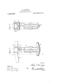
' l hr pnrpuse M drawing lhe jaws i is? Am; bring n'elcrnhl v invaded i'ne ilOi .n ninnedmlr EH'ORE iui-ly nnde w i aiding i'nrn'nrd from mm Hie bml v of the fulcrum so i section on the line 2--2, Fig. 1, showing the PUi'LlOliS of a irnssed brake eazn wn h which my invention is concerned i1 reprebenls the compression member, B
The tension member and C the strui, f-a
welblnniwn type of lrussed brake beam,
The compression member A. is shown c011- sl'rncl'ed ef channel-min, but it may be of an other section. The tension member 15 18 of rennd section, but it may be 0f: any other form adapted l0 provide abnl'inent for the fulcrum C and to transmit ihe braking siress lzmn lhe same. "[0 the brake shoes.
The slrnt- C illustrated as '21 one-piece rusting, but this characteristic is essential only so far as eoncerns that end which is designed to embrace and bind upen the memberof the brake beam, ordinarily the compression member only, though, obviously the Tension member as Well, if desired.
The embracing end isproviclod With jaws 1 designed to embrace four sides of the coinpre ,iun member A, namely at the points 2, 3 and 4, so that the strut is not only milzlpied m in) if ihe member A be the cmnpression member, but firmly bind upon the member A and hold the strut against displznicenienh 'Belween the points ll, the bearing: is divided nil-t stresses of compression 80 so that the par-is 1 coiisii'itnie jaws which may be pressed into binding relation to the member A. To afl'm'd necessary flexibility to he jaws 1, the strut is provided with a slot exiei'n'ling forward from the bearing 1 snliicient distance to permit the jaws l being pressed together withort doing vie-- lence lo the metal of the strut. To effeciirely press the jaws togelher and hold lheln in bindinp' relation in the 1'ne1nl.)er 7 a rivet U or the like is introduced through ihe in position to extend aeross l'he slot The strut formed of a malleable casting with the bearing of such size as to lit easily liYOi the member A, and it is applied by sliding it endwise over said member before the members A. and B are assembled, after which it 1s lirlnly clamped in POSIUOD by means of its rivet (in Vii} 10 hearing faces 2 and 4- are preferably designed wirh snlieieni inner jams to bind firmly when the bearing faces are :ed to their seals on the beambe desired l0 apply lhe strut afier strut to cause the i i .1: l the two main. members of the beam are as- 119 sembled, the aws will be given sufficient initial spread to enable the strut to swing on mate position when the aWs will be pressed together.
In adapting the strut to some sections of compression member, it may be desirable to locate the rivet elsewhere than in the relative position sh0Wn-even in some instances, in rear of the compression member.
I claim A brake beam comprising a compression member, a tension member and a strut having its ends provided with bearings to receive said compression and tension members; the compression member bearing comprising a pair of jaws adapted to receive the compression member between them, whereby they bear upwardly and downwardly upon the compression member; said, jaws being recessed to conform to the compression member, whereby each is adapted to bear forwardly and rearwardlyagainst the compression member 3 and said jaws being separated by a slot extending inwardly from the compression member bearing to give resiliency to the jaws and having a rivetextending through the jaws across said slot adjacent to but not intersecting the compression member bearing.
The foregoing specification signed at Cleveland, Ohio, this 14th day of March,
PHILIP T. HANDIGES. In presence of- R. VVAGNER, R. J. Corn.
Priority Applications (1)
| Application Number | Priority Date | Filing Date | Title |
|---|---|---|---|
| US62195311A US1062330A (en) | 1911-04-18 | 1911-04-18 | Brake-beam fulcrum. |
Applications Claiming Priority (1)
| Application Number | Priority Date | Filing Date | Title |
|---|---|---|---|
| US62195311A US1062330A (en) | 1911-04-18 | 1911-04-18 | Brake-beam fulcrum. |
Publications (1)
| Publication Number | Publication Date |
|---|---|
| US1062330A true US1062330A (en) | 1913-05-20 |
Family
ID=3130576
Family Applications (1)
| Application Number | Title | Priority Date | Filing Date |
|---|---|---|---|
| US62195311A Expired - Lifetime US1062330A (en) | 1911-04-18 | 1911-04-18 | Brake-beam fulcrum. |
Country Status (1)
| Country | Link |
|---|---|
| US (1) | US1062330A (en) |
-
1911
- 1911-04-18 US US62195311A patent/US1062330A/en not_active Expired - Lifetime
Similar Documents
| Publication | Publication Date | Title |
|---|---|---|
| US617484A (en) | Push-rod | |
| US1272778A (en) | Brake-beam. | |
| US44434A (en) | Beenaed j | |
| US1475286A (en) | Railway-car brake | |
| US690824A (en) | Brake-beam. | |
| US1219435A (en) | Trussed brake-beam. | |
| US601032A (en) | Railway | |
| US1605553A (en) | Equalizer bar for railway-car trucks | |
| US2096430A (en) | Brake shoe for railway cars | |
| US902138A (en) | Railway brake-beam. | |
| US1784896A (en) | Brake-beam structure | |
| US1057521A (en) | Friction draft-rigging. | |
| US1460633A (en) | Rope clamp | |
| US981619A (en) | Railway brake-beam. | |
| US1340007A (en) | Metal brake-beam | |
| US604442A (en) | Car-buffer | |
| US117390A (en) | Improvement in axle-boxes | |
| US1198064A (en) | Safety-hanger for brake-beams for traction-cars. | |
| US1555519A (en) | Railway-car truck | |
| US1959582A (en) | Friction shock absorbing mechanism | |
| US832597A (en) | Brake-beam for railway-cars. | |
| US1303375A (en) | Friction shock-absorbing mechanism | |
| US1121212A (en) | Forge-steel fulcrum for brake-beams. | |
| US1011034A (en) | Friction draft-gear. | |
| US1819815A (en) | Pipe clamp |