US10622142B2 - Concrete-embedded wireless power transfer coil - Google Patents
Concrete-embedded wireless power transfer coil Download PDFInfo
- Publication number
- US10622142B2 US10622142B2 US15/716,358 US201715716358A US10622142B2 US 10622142 B2 US10622142 B2 US 10622142B2 US 201715716358 A US201715716358 A US 201715716358A US 10622142 B2 US10622142 B2 US 10622142B2
- Authority
- US
- United States
- Prior art keywords
- layer
- wire
- wireless power
- stranded
- stranded wire
- Prior art date
- Legal status (The legal status is an assumption and is not a legal conclusion. Google has not performed a legal analysis and makes no representation as to the accuracy of the status listed.)
- Active
Links
- 238000012546 transfer Methods 0.000 title claims abstract description 34
- 239000003365 glass fiber Substances 0.000 claims description 7
- 238000009413 insulation Methods 0.000 claims description 5
- 239000004677 Nylon Substances 0.000 claims description 2
- 229920001778 nylon Polymers 0.000 claims description 2
- XLYOFNOQVPJJNP-UHFFFAOYSA-N water Substances O XLYOFNOQVPJJNP-UHFFFAOYSA-N 0.000 claims description 2
- 238000000034 method Methods 0.000 abstract description 6
- 239000012466 permeate Substances 0.000 abstract 1
- 239000000463 material Substances 0.000 description 19
- 239000002002 slurry Substances 0.000 description 8
- 239000000835 fiber Substances 0.000 description 5
- 239000004568 cement Substances 0.000 description 4
- 230000037361 pathway Effects 0.000 description 4
- 230000003247 decreasing effect Effects 0.000 description 2
- 238000012360 testing method Methods 0.000 description 2
- 239000003513 alkali Substances 0.000 description 1
- 230000000593 degrading effect Effects 0.000 description 1
- 238000013461 design Methods 0.000 description 1
- 230000000694 effects Effects 0.000 description 1
- 238000003780 insertion Methods 0.000 description 1
- 230000037431 insertion Effects 0.000 description 1
- 239000011810 insulating material Substances 0.000 description 1
- 230000007774 longterm Effects 0.000 description 1
- 239000000203 mixture Substances 0.000 description 1
- 238000005457 optimization Methods 0.000 description 1
- 229920000642 polymer Polymers 0.000 description 1
- 229920000098 polyolefin Polymers 0.000 description 1
- 238000007493 shaping process Methods 0.000 description 1
- 238000005728 strengthening Methods 0.000 description 1
- 238000004804 winding Methods 0.000 description 1
- 229910000859 α-Fe Inorganic materials 0.000 description 1
Images


Classifications
-
- H—ELECTRICITY
- H01—ELECTRIC ELEMENTS
- H01F—MAGNETS; INDUCTANCES; TRANSFORMERS; SELECTION OF MATERIALS FOR THEIR MAGNETIC PROPERTIES
- H01F38/00—Adaptations of transformers or inductances for specific applications or functions
- H01F38/14—Inductive couplings
-
- B—PERFORMING OPERATIONS; TRANSPORTING
- B60—VEHICLES IN GENERAL
- B60L—PROPULSION OF ELECTRICALLY-PROPELLED VEHICLES; SUPPLYING ELECTRIC POWER FOR AUXILIARY EQUIPMENT OF ELECTRICALLY-PROPELLED VEHICLES; ELECTRODYNAMIC BRAKE SYSTEMS FOR VEHICLES IN GENERAL; MAGNETIC SUSPENSION OR LEVITATION FOR VEHICLES; MONITORING OPERATING VARIABLES OF ELECTRICALLY-PROPELLED VEHICLES; ELECTRIC SAFETY DEVICES FOR ELECTRICALLY-PROPELLED VEHICLES
- B60L5/00—Current collectors for power supply lines of electrically-propelled vehicles
- B60L5/005—Current collectors for power supply lines of electrically-propelled vehicles without mechanical contact between the collector and the power supply line
-
- B—PERFORMING OPERATIONS; TRANSPORTING
- B60—VEHICLES IN GENERAL
- B60L—PROPULSION OF ELECTRICALLY-PROPELLED VEHICLES; SUPPLYING ELECTRIC POWER FOR AUXILIARY EQUIPMENT OF ELECTRICALLY-PROPELLED VEHICLES; ELECTRODYNAMIC BRAKE SYSTEMS FOR VEHICLES IN GENERAL; MAGNETIC SUSPENSION OR LEVITATION FOR VEHICLES; MONITORING OPERATING VARIABLES OF ELECTRICALLY-PROPELLED VEHICLES; ELECTRIC SAFETY DEVICES FOR ELECTRICALLY-PROPELLED VEHICLES
- B60L53/00—Methods of charging batteries, specially adapted for electric vehicles; Charging stations or on-board charging equipment therefor; Exchange of energy storage elements in electric vehicles
- B60L53/10—Methods of charging batteries, specially adapted for electric vehicles; Charging stations or on-board charging equipment therefor; Exchange of energy storage elements in electric vehicles characterised by the energy transfer between the charging station and the vehicle
- B60L53/12—Inductive energy transfer
-
- E—FIXED CONSTRUCTIONS
- E01—CONSTRUCTION OF ROADS, RAILWAYS, OR BRIDGES
- E01C—CONSTRUCTION OF, OR SURFACES FOR, ROADS, SPORTS GROUNDS, OR THE LIKE; MACHINES OR AUXILIARY TOOLS FOR CONSTRUCTION OR REPAIR
- E01C23/00—Auxiliary devices or arrangements for constructing, repairing, reconditioning, or taking-up road or like surfaces
-
- E—FIXED CONSTRUCTIONS
- E01—CONSTRUCTION OF ROADS, RAILWAYS, OR BRIDGES
- E01C—CONSTRUCTION OF, OR SURFACES FOR, ROADS, SPORTS GROUNDS, OR THE LIKE; MACHINES OR AUXILIARY TOOLS FOR CONSTRUCTION OR REPAIR
- E01C9/00—Special pavings; Pavings for special parts of roads or airfields
-
- H—ELECTRICITY
- H01—ELECTRIC ELEMENTS
- H01F—MAGNETS; INDUCTANCES; TRANSFORMERS; SELECTION OF MATERIALS FOR THEIR MAGNETIC PROPERTIES
- H01F27/00—Details of transformers or inductances, in general
- H01F27/28—Coils; Windings; Conductive connections
- H01F27/2823—Wires
-
- H—ELECTRICITY
- H01—ELECTRIC ELEMENTS
- H01F—MAGNETS; INDUCTANCES; TRANSFORMERS; SELECTION OF MATERIALS FOR THEIR MAGNETIC PROPERTIES
- H01F27/00—Details of transformers or inductances, in general
- H01F27/28—Coils; Windings; Conductive connections
- H01F27/32—Insulating of coils, windings, or parts thereof
-
- H—ELECTRICITY
- H01—ELECTRIC ELEMENTS
- H01F—MAGNETS; INDUCTANCES; TRANSFORMERS; SELECTION OF MATERIALS FOR THEIR MAGNETIC PROPERTIES
- H01F41/00—Apparatus or processes specially adapted for manufacturing or assembling magnets, inductances or transformers; Apparatus or processes specially adapted for manufacturing materials characterised by their magnetic properties
- H01F41/02—Apparatus or processes specially adapted for manufacturing or assembling magnets, inductances or transformers; Apparatus or processes specially adapted for manufacturing materials characterised by their magnetic properties for manufacturing cores, coils, or magnets
- H01F41/04—Apparatus or processes specially adapted for manufacturing or assembling magnets, inductances or transformers; Apparatus or processes specially adapted for manufacturing materials characterised by their magnetic properties for manufacturing cores, coils, or magnets for manufacturing coils
-
- Y—GENERAL TAGGING OF NEW TECHNOLOGICAL DEVELOPMENTS; GENERAL TAGGING OF CROSS-SECTIONAL TECHNOLOGIES SPANNING OVER SEVERAL SECTIONS OF THE IPC; TECHNICAL SUBJECTS COVERED BY FORMER USPC CROSS-REFERENCE ART COLLECTIONS [XRACs] AND DIGESTS
- Y02—TECHNOLOGIES OR APPLICATIONS FOR MITIGATION OR ADAPTATION AGAINST CLIMATE CHANGE
- Y02T—CLIMATE CHANGE MITIGATION TECHNOLOGIES RELATED TO TRANSPORTATION
- Y02T10/00—Road transport of goods or passengers
- Y02T10/60—Other road transportation technologies with climate change mitigation effect
- Y02T10/70—Energy storage systems for electromobility, e.g. batteries
-
- Y—GENERAL TAGGING OF NEW TECHNOLOGICAL DEVELOPMENTS; GENERAL TAGGING OF CROSS-SECTIONAL TECHNOLOGIES SPANNING OVER SEVERAL SECTIONS OF THE IPC; TECHNICAL SUBJECTS COVERED BY FORMER USPC CROSS-REFERENCE ART COLLECTIONS [XRACs] AND DIGESTS
- Y02—TECHNOLOGIES OR APPLICATIONS FOR MITIGATION OR ADAPTATION AGAINST CLIMATE CHANGE
- Y02T—CLIMATE CHANGE MITIGATION TECHNOLOGIES RELATED TO TRANSPORTATION
- Y02T10/00—Road transport of goods or passengers
- Y02T10/60—Other road transportation technologies with climate change mitigation effect
- Y02T10/7072—Electromobility specific charging systems or methods for batteries, ultracapacitors, supercapacitors or double-layer capacitors
-
- Y—GENERAL TAGGING OF NEW TECHNOLOGICAL DEVELOPMENTS; GENERAL TAGGING OF CROSS-SECTIONAL TECHNOLOGIES SPANNING OVER SEVERAL SECTIONS OF THE IPC; TECHNICAL SUBJECTS COVERED BY FORMER USPC CROSS-REFERENCE ART COLLECTIONS [XRACs] AND DIGESTS
- Y02—TECHNOLOGIES OR APPLICATIONS FOR MITIGATION OR ADAPTATION AGAINST CLIMATE CHANGE
- Y02T—CLIMATE CHANGE MITIGATION TECHNOLOGIES RELATED TO TRANSPORTATION
- Y02T90/00—Enabling technologies or technologies with a potential or indirect contribution to GHG emissions mitigation
- Y02T90/10—Technologies relating to charging of electric vehicles
- Y02T90/14—Plug-in electric vehicles
Definitions
- the present disclosure relates to wireless power transfer coils, more particularly, to novel systems and methods for embedding a wireless power transfer coil in concrete.
- Wireless power transfer coils may be embedded in concrete or roadways for the purpose of transferring electrical energy to a wireless power transfer coil in an automobile.
- This invention solves the problems of embedding wireless power transfer coils in a roadway or pathway.
- One of the methods for doing so is to add a thickness of particular materials around the coil so as to separate it from the material surrounding the coil (structural material) which acts as a degrading element to the performance of the coil.
- Another considerable concern with embedded coils is to maintain the strength characteristics of the structural material when the coil is placed within.
- One method proposed for increasing the strength is to alternatingly offset each winding vertically thus increasing the space between each coil but not increasing the overall diameter of the coil.
- offset coils Another benefit of the offset coils is an optimization of the magnetic field shaping that occurs from the position of one coil relative to the other.
- FIG. 1 illustrates a wireless power transfer coil assembly in a road or pathway
- FIG. 2 illustrates and exploded view of the wireless power transfer coil assembly of FIG. 1 ;
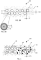
- FIG. 3A illustrates a portion of a wireless power transfer coil embedded in a concrete structure
- FIG. 3B illustrates an insulated stranded wire
- FIG. 4 illustrates a portion of a wireless power transfer coil embedded in another concrete structure.
- FIG. 1 illustrates a wireless power transfer coil assembly 100 located in a road or pathway 34 where trucks, cars, or other heavy objects can impart significant loads onto the wireless power transfer coil.
- FIG. 2 shows and exploded view of a traditional wireless power transfer coil assembly 100 .
- Traditional wireless power transfer coils are not embedded in concrete, but are instead located in a housing 35 with a cover 31 .
- the cover 31 may be installed flush with the road or pathway surface 30 .
- Other parts of the wireless power transfer coil assembly 100 include ferrite bars 32 and a shield plate 33 .
- the cover 31 and housing 35 are designed to protect the wireless power transfer coil assembly 100 and redirect loads from heavy objects around the wireless power transfer coil assembly 100 .
- the cover 31 and housing 35 can be difficult to integrate with the road 34 or road surface 30 for long-term durability.
- the inventors of the present disclosure identified that it would be ideal if the cover 31 or housing 35 could be made from the same materials as the road 34 , such as concrete. However, in order to do so, the inventors identified the need to design the coil such that loads imparted on the wireless power transfer coil assembly 100 could be transferred through the coil without damaging the stranded wire in the coil 40 , or other parts of the wireless power transfer coil assembly 100 , without compromising performance.
- FIG. 1 illustrates a coil 40 arrangement where the coils are placed side-by-side without a gap between them. Coils 40 are placed side-by-side without a gap to increase the strength of the varying magnetic field created by the wireless power transfer coil assembly 100 and to minimize the circumference of the wireless power transfer coil assembly 100 .
- coil 40 would create gap between a top and bottom layer of concrete above and below the coil 40 . Loads applied to the top layer of concrete would transfer through the more flexible stranded wire in the coil 40 , causing the top layer of concrete to eventually crack or otherwise degrade.
- One possible solution tested by the inventors of the present disclosure was to embed a wireless power transfer coil directly into a concrete slurry and have the concrete cure around each of the individual stranded wires that make up the coil.
- the inventors tested wireless power transfer coils made of litz wire. Other types of stranded wire may also be used.
- the coil resistance increased by more than 100 times and the inductance decreased by more than 100 times.
- the increase in resistance and decrease in inductance was unexpected.
- a wireless power transfer coil should retain minimum resistance and high inductance.
- the inventors expected no changed in resistance or inductance because the litz wire and the individual litz fibers within the litz wire are insulated.
- the inventors found that as the concrete cured, the resistance through the wireless power transfer coil decreased but still remained orders of magnitude higher than the original coil before it was imbedded into the concrete slurry. This post-cure high resistance and low inductance was also unexpected.
- Embodiments of the present disclosure solve the resistance and structural load problem created by placing a wireless power transfer coil directly in a cement slurry.
- the inventors found that increasing the thickness and integrity of the insulating material around offset stranded wires substantially reduced the effect of the increased resistance and reduced inductance.
- FIG. 3A illustrates an embodiment of the present disclosure where a portion of a wireless power transfer coil 200 of individual stranded wires 45 are embedded in a concrete structure 43 .
- FIG. 3 illustrates a first and second layer, 51 and 52 , respectively, of continuously strung stranded wire 45 .
- the first 51 and second 52 layers are arranged in a circular pattern, where the first layer 51 is position above the second layer 52 such that the stranded wire 45 of the first layer 51 are offset vertically by a vertical wire-to-wire distance 46 A.
- the stranded wires 45 are vertically offset with a center-to-center distance equal to the stranded wire diameter such that the vertical wire-to-wire distance 46 A is zero inches.
- the stranded wires 45 between the first layer 51 and the second layer 52 are horizontally offset with a center-to-center distance equal to the stranded wire diameter such that the horizontal wire-to-wire distance 47 A is zero inches.
- the horizontal wire-to-wire distance 47 A minimizes the coil circumference.
- the vertical wire-to-wire distance 46 A allows the concrete mixture 44 to more readily flow between the stranded wires 45 to create a continuous structure of concrete 44 through the coil 200 .
- the continuous concrete 44 flow through the coil 200 acts to transfer any load place on top of the coils 200 to below the coil 200 .
- FIG. 3B illustrates a magnified view of an example stranded wire 45 with litz fibers 42 .
- the stranded wire 45 used by the inventors in tests contained 1,650 strands (or fibers) of 38-AWG strands with a double-nylon jacket wrap 41 . Additionally, the individual litz strands 42 were insulated (not shown). Other types of stranded, litz, or non-litz wire could be used as well to optimize the performance.
- Stranded wire 45 has additional insulation 43 , which increased the distance between litz fibers 42 and the structural material or concrete 44 .
- the inventors enveloped the stranded wires 45 in a layer of water-resistant polyolefin heat-shrink (additional insulation 44 ).
- the insulation thickness was between approximately 0.015 to 0.035 inches, although other thicknesses outside of this range could be optimal under various conditions.
- the thickness of insulation 43 was sufficient such that the litz fibers 42 are spaced a distance from the cement or structural material 44 . The inventors believe that this increased distance reduced the dissipation factor of the cement or structural material 44 so as to minimally impact the resistance of the stranded wire 45 in the coil 200 .
- FIG. 4 illustrates another vertical wire-to-wire distance 46 B.
- vertical wire-to-wire distance 46 B is about one-fourth the diameter of the stranded wire 45 .
- Other offset distances are possible.
- the vertical wire-to-wire distance 46 B may be increased to allow for the insertion of strengthening materials within cement or structural material 44 .
- FIG. 4 illustrates glass fiber 48 or large aggregate 49 embedded into the concrete or structural material 44 .
- the glass fiber is an alkali-resistant glass fiber and the concrete or structure material also contains a polymer admixture.
- the large aggregate is generally greater than 3 ⁇ 8 inches.
- Glass fiber 48 or large aggregate 49 can increase the compressive strength of the concrete or structural material 44 .
- the combined glass fiber 48 and concrete slurry 44 or aggregate 49 and concrete slurry 44 may need to be hand-packed between the stranded wires 45 to avoid large air-pockets between the stranded wires 45 .
- the combined glass fiber 48 and concrete slurry 44 or aggregate 49 and concrete slurry 44 may be vibrated immediately after being poured to fill-in any pockets between the stranded wires 45 .
Landscapes
- Engineering & Computer Science (AREA)
- Power Engineering (AREA)
- Transportation (AREA)
- Mechanical Engineering (AREA)
- Architecture (AREA)
- Civil Engineering (AREA)
- Structural Engineering (AREA)
- Manufacturing & Machinery (AREA)
- Coils Of Transformers For General Uses (AREA)
- Near-Field Transmission Systems (AREA)
Abstract
Description
Claims (5)
Priority Applications (1)
| Application Number | Priority Date | Filing Date | Title |
|---|---|---|---|
| US15/716,358 US10622142B2 (en) | 2016-09-26 | 2017-09-27 | Concrete-embedded wireless power transfer coil |
Applications Claiming Priority (2)
| Application Number | Priority Date | Filing Date | Title |
|---|---|---|---|
| US201662399922P | 2016-09-26 | 2016-09-26 | |
| US15/716,358 US10622142B2 (en) | 2016-09-26 | 2017-09-27 | Concrete-embedded wireless power transfer coil |
Publications (2)
| Publication Number | Publication Date |
|---|---|
| US20180151293A1 US20180151293A1 (en) | 2018-05-31 |
| US10622142B2 true US10622142B2 (en) | 2020-04-14 |
Family
ID=62192892
Family Applications (1)
| Application Number | Title | Priority Date | Filing Date |
|---|---|---|---|
| US15/716,358 Active US10622142B2 (en) | 2016-09-26 | 2017-09-27 | Concrete-embedded wireless power transfer coil |
Country Status (1)
| Country | Link |
|---|---|
| US (1) | US10622142B2 (en) |
Cited By (2)
| Publication number | Priority date | Publication date | Assignee | Title |
|---|---|---|---|---|
| US11101692B2 (en) * | 2017-04-07 | 2021-08-24 | Sew-Eurodrive Gmbh & Co. Kg | Method for producing a system for inductively transmitting energy to a mobile part, and device for carrying out the method |
| WO2024175688A3 (en) * | 2023-02-24 | 2024-10-17 | Brusa Elektronik Ag | Main coil assembly for a ground module gpm or for a vehicle module cpm of an inductive charging system for a vehicle |
Families Citing this family (3)
| Publication number | Priority date | Publication date | Assignee | Title |
|---|---|---|---|---|
| WO2019237848A1 (en) * | 2018-06-11 | 2019-12-19 | Oppo广东移动通信有限公司 | Wireless charging coil, wireless charging assembly and electronic device |
| TWI658482B (en) * | 2018-07-10 | 2019-05-01 | 德宙佑電股份有限公司 | Inductive twisted wire method |
| CN108987099B (en) * | 2018-07-23 | 2020-04-21 | 德宙佑电股份有限公司 | Inductor twisted wire method |
Citations (15)
| Publication number | Priority date | Publication date | Assignee | Title |
|---|---|---|---|---|
| US3808569A (en) | 1968-06-12 | 1974-04-30 | Science Res Council | Electromagnet with windings embedded in and insulated by compressively stressed concrete |
| US20110287713A1 (en) | 2010-05-18 | 2011-11-24 | University Of South Carolina | Wireless Power Transfer to Embedded Sensors |
| US20120218068A1 (en) * | 2011-02-28 | 2012-08-30 | Equos Research Co., Ltd. | Antenna |
| US20130181668A1 (en) * | 2010-12-01 | 2013-07-18 | Panasonic Corporation | Non-contact charging module and non-contact charging instrument |
| US20130328412A1 (en) * | 2011-06-30 | 2013-12-12 | Paul Vahle Gmbh & Co. Kg | Flat coil for a contactless inductive energy transmission |
| US20140284159A1 (en) * | 2011-10-28 | 2014-09-25 | Auckland Uniservices Limited | Non-ferrite structures for inductive power transfer |
| US20150123489A1 (en) | 2012-07-26 | 2015-05-07 | Ihi Corporation | Wireless power-supplying system |
| US20150145634A1 (en) * | 2013-11-25 | 2015-05-28 | A.K. Stamping Company, Inc. | Wireless Charging Coil |
| US20150170833A1 (en) * | 2013-12-17 | 2015-06-18 | Qualcomm Incorporated | Coil topologies for inductive power transfer |
| US20150179335A1 (en) * | 2013-12-20 | 2015-06-25 | Samsung Electro-Mechanics Co., Ltd. | Coil device, and wireless power transmitter and wireless power receiver having the same |
| US20150367739A1 (en) * | 2013-02-11 | 2015-12-24 | Sew-Eurodrive Gmbh & Co. Kg | Device Having a Winding Configuration and System, Especially Charging Station, for the Non-Contact Transmission of Energy to an Electric-Powered Vehicle, Having a Winding Configuration |
| US20160147965A1 (en) | 2014-11-21 | 2016-05-26 | Nihon Kohden Corporation | Medical system |
| US20160156215A1 (en) * | 2013-06-20 | 2016-06-02 | Lg Innotek Co., Ltd. | Receiving Antenna and Wireless Power Receiving Device Including the Same |
| US20160254706A1 (en) * | 2015-02-24 | 2016-09-01 | Tdk Corporation | Coil unit, wireless power feeding device, wireless power receiving device, and wireless power transmission device |
| US20170237295A1 (en) * | 2014-08-20 | 2017-08-17 | Toyota Jidosha Kabushiki Kaisha | Power transmission device, method for manufacturing the same, power reception device and method for manufacturing the same |
-
2017
- 2017-09-27 US US15/716,358 patent/US10622142B2/en active Active
Patent Citations (16)
| Publication number | Priority date | Publication date | Assignee | Title |
|---|---|---|---|---|
| US3808569A (en) | 1968-06-12 | 1974-04-30 | Science Res Council | Electromagnet with windings embedded in and insulated by compressively stressed concrete |
| US20110287713A1 (en) | 2010-05-18 | 2011-11-24 | University Of South Carolina | Wireless Power Transfer to Embedded Sensors |
| US8913952B2 (en) | 2010-05-18 | 2014-12-16 | University Of South Carolina | Wireless power transfer to embedded sensors |
| US20130181668A1 (en) * | 2010-12-01 | 2013-07-18 | Panasonic Corporation | Non-contact charging module and non-contact charging instrument |
| US20120218068A1 (en) * | 2011-02-28 | 2012-08-30 | Equos Research Co., Ltd. | Antenna |
| US20130328412A1 (en) * | 2011-06-30 | 2013-12-12 | Paul Vahle Gmbh & Co. Kg | Flat coil for a contactless inductive energy transmission |
| US20140284159A1 (en) * | 2011-10-28 | 2014-09-25 | Auckland Uniservices Limited | Non-ferrite structures for inductive power transfer |
| US20150123489A1 (en) | 2012-07-26 | 2015-05-07 | Ihi Corporation | Wireless power-supplying system |
| US20150367739A1 (en) * | 2013-02-11 | 2015-12-24 | Sew-Eurodrive Gmbh & Co. Kg | Device Having a Winding Configuration and System, Especially Charging Station, for the Non-Contact Transmission of Energy to an Electric-Powered Vehicle, Having a Winding Configuration |
| US20160156215A1 (en) * | 2013-06-20 | 2016-06-02 | Lg Innotek Co., Ltd. | Receiving Antenna and Wireless Power Receiving Device Including the Same |
| US20150145634A1 (en) * | 2013-11-25 | 2015-05-28 | A.K. Stamping Company, Inc. | Wireless Charging Coil |
| US20150170833A1 (en) * | 2013-12-17 | 2015-06-18 | Qualcomm Incorporated | Coil topologies for inductive power transfer |
| US20150179335A1 (en) * | 2013-12-20 | 2015-06-25 | Samsung Electro-Mechanics Co., Ltd. | Coil device, and wireless power transmitter and wireless power receiver having the same |
| US20170237295A1 (en) * | 2014-08-20 | 2017-08-17 | Toyota Jidosha Kabushiki Kaisha | Power transmission device, method for manufacturing the same, power reception device and method for manufacturing the same |
| US20160147965A1 (en) | 2014-11-21 | 2016-05-26 | Nihon Kohden Corporation | Medical system |
| US20160254706A1 (en) * | 2015-02-24 | 2016-09-01 | Tdk Corporation | Coil unit, wireless power feeding device, wireless power receiving device, and wireless power transmission device |
Cited By (3)
| Publication number | Priority date | Publication date | Assignee | Title |
|---|---|---|---|---|
| US11101692B2 (en) * | 2017-04-07 | 2021-08-24 | Sew-Eurodrive Gmbh & Co. Kg | Method for producing a system for inductively transmitting energy to a mobile part, and device for carrying out the method |
| US11594914B2 (en) | 2017-04-07 | 2023-02-28 | Sew-Eurodrive Gmbh & Co. Kg | Method for producing a system for inductively transmitting energy to a mobile part, and device for carrying out the method |
| WO2024175688A3 (en) * | 2023-02-24 | 2024-10-17 | Brusa Elektronik Ag | Main coil assembly for a ground module gpm or for a vehicle module cpm of an inductive charging system for a vehicle |
Also Published As
| Publication number | Publication date |
|---|---|
| US20180151293A1 (en) | 2018-05-31 |
Similar Documents
| Publication | Publication Date | Title |
|---|---|---|
| US10622142B2 (en) | Concrete-embedded wireless power transfer coil | |
| CN104870243B (en) | Device having a winding arrangement and arrangement, in particular a charging station, for contactless transfer of energy to an electric vehicle, having a winding arrangement | |
| CN107615417B (en) | Induction coil unit with fiber reinforced ferrite core | |
| CN100514514C (en) | Transformer and transformer coil for a transformer | |
| CN102969844B (en) | Large ac machines stator winding end colligation technique for fixing | |
| US8797133B2 (en) | Transformer with shielding rings in windings | |
| US10770932B2 (en) | Magnetizable concrete composite for road-embedded wireless power transfer | |
| US11222745B2 (en) | Coil and non-contact power supply device | |
| CN102349122A (en) | Coil assemblies for transformers or choke coils | |
| US20180211773A1 (en) | Induction Charging System Having a Housing Structure Having Carbon Fibers That Are Without Contact | |
| CN1301391A (en) | Amorphous metal transformer having a generally rectangular coil | |
| CN112204687B (en) | Inductive energy transmitter/receiver for inductive chargers for electric vehicles | |
| JP7557977B2 (en) | Embedded structure of coil for non-contact power supply | |
| US8360039B2 (en) | Ignition coil | |
| CN108696029B (en) | Fixing structure and binding process for stator winding end part of low-speed high-torque permanent magnet direct-drive motor | |
| CA2569260A1 (en) | Transformer coil assembly | |
| CA2758282C (en) | Power transformer with amorphous core | |
| CN103310918B (en) | Combined type plug and the insulator with this plug | |
| US20160172095A1 (en) | Wound Core for Stationary Induction Apparatus | |
| CN102497065A (en) | Universal winding former for high-voltage motor windings | |
| CN205738733U (en) | A kind of coil of strip preventer | |
| CN204029482U (en) | Insulated wire and transformer | |
| WO2019115695A1 (en) | A method of manufacturing a winding structure unit and such a winding structure unit | |
| CN104934206A (en) | Smoothing reactor of insulating resin pouring type | |
| EP2479764B1 (en) | Resin molded coil and molded transformer using the same |
Legal Events
| Date | Code | Title | Description |
|---|---|---|---|
| FEPP | Fee payment procedure |
Free format text: ENTITY STATUS SET TO UNDISCOUNTED (ORIGINAL EVENT CODE: BIG.); ENTITY STATUS OF PATENT OWNER: MICROENTITY |
|
| AS | Assignment |
Owner name: UTAH STATE UNIVERSITY, UTAH Free format text: ASSIGNMENT OF ASSIGNORS INTEREST;ASSIGNORS:BOHM, RYAN J.;GARDNER, TREVOR G.;HALLING, MARVIN;AND OTHERS;SIGNING DATES FROM 20170113 TO 20170127;REEL/FRAME:043710/0409 |
|
| FEPP | Fee payment procedure |
Free format text: ENTITY STATUS SET TO SMALL (ORIGINAL EVENT CODE: SMAL); ENTITY STATUS OF PATENT OWNER: MICROENTITY Free format text: ENTITY STATUS SET TO MICRO (ORIGINAL EVENT CODE: MICR); ENTITY STATUS OF PATENT OWNER: MICROENTITY |
|
| FEPP | Fee payment procedure |
Free format text: PETITION RELATED TO MAINTENANCE FEES GRANTED (ORIGINAL EVENT CODE: PTGR); ENTITY STATUS OF PATENT OWNER: MICROENTITY |
|
| STPP | Information on status: patent application and granting procedure in general |
Free format text: NON FINAL ACTION MAILED |
|
| STPP | Information on status: patent application and granting procedure in general |
Free format text: RESPONSE TO NON-FINAL OFFICE ACTION ENTERED AND FORWARDED TO EXAMINER |
|
| STPP | Information on status: patent application and granting procedure in general |
Free format text: FINAL REJECTION MAILED |
|
| STPP | Information on status: patent application and granting procedure in general |
Free format text: NOTICE OF ALLOWANCE MAILED -- APPLICATION RECEIVED IN OFFICE OF PUBLICATIONS |
|
| STCF | Information on status: patent grant |
Free format text: PATENTED CASE |
|
| MAFP | Maintenance fee payment |
Free format text: PAYMENT OF MAINTENANCE FEE, 4TH YEAR, MICRO ENTITY (ORIGINAL EVENT CODE: M3551); ENTITY STATUS OF PATENT OWNER: MICROENTITY Year of fee payment: 4 |