US1062095A - Piston packing-ring. - Google Patents
Piston packing-ring. Download PDFInfo
- Publication number
- US1062095A US1062095A US73894812A US1912738948A US1062095A US 1062095 A US1062095 A US 1062095A US 73894812 A US73894812 A US 73894812A US 1912738948 A US1912738948 A US 1912738948A US 1062095 A US1062095 A US 1062095A
- Authority
- US
- United States
- Prior art keywords
- ring
- piston
- split
- piston packing
- inward
- Prior art date
- Legal status (The legal status is an assumption and is not a legal conclusion. Google has not performed a legal analysis and makes no representation as to the accuracy of the status listed.)
- Expired - Lifetime
Links
- 206010044625 Trichorrhexis Diseases 0.000 description 2
- 239000000463 material Substances 0.000 description 2
- 238000012856 packing Methods 0.000 description 2
- 230000015572 biosynthetic process Effects 0.000 description 1
- 230000006835 compression Effects 0.000 description 1
- 238000007906 compression Methods 0.000 description 1
- 239000012530 fluid Substances 0.000 description 1
- 230000001788 irregular Effects 0.000 description 1
- 239000002184 metal Substances 0.000 description 1
- 230000003014 reinforcing effect Effects 0.000 description 1
- 229910000679 solder Inorganic materials 0.000 description 1
Images
Classifications
-
- F—MECHANICAL ENGINEERING; LIGHTING; HEATING; WEAPONS; BLASTING
- F16—ENGINEERING ELEMENTS AND UNITS; GENERAL MEASURES FOR PRODUCING AND MAINTAINING EFFECTIVE FUNCTIONING OF MACHINES OR INSTALLATIONS; THERMAL INSULATION IN GENERAL
- F16J—PISTONS; CYLINDERS; SEALINGS
- F16J9/00—Piston-rings, e.g. non-metallic piston-rings, seats therefor; Ring sealings of similar construction
- F16J9/12—Details
- F16J9/14—Joint-closures
Definitions
- This .invention elatesto packing rings, and more especially to those intended to be used around pistons such as are employed within the cylinders of gasolcne engines; and its object is to prolong the life of such a piston ringby reducing the leakage past it where it is split and therefore enabling it to be used longer before it must neces-v sarily be replaced by a new one.
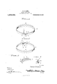
- FIG. 1 is a perspective view of a split piston ring embodying my improvements, looking at the outside thereof wlth the split ends closed together; and Fig. 2 is a similar view looking at the inside of the split ends which latter are in this instance slightly separated.
- Fig. 3 is an enlarged perspective detail of the device itself detached from the ring; and
- Fig. 4 is an enlarged cross section on the line l4 of Fig. 1.
- the letter R designates a piston ring whichis made slightly crescent shaped in the present instance, being thicker at the point P and split directly opposite thereto.
- the manner of splitting the ring is not essential to the present invention but Ihavc illustrated each end as cut off oblique on the line and as reduced in width at its edges slightly as at 1 so as to form op positely disposed shoulders 2, 2 on both ends of the ring.
- the present invention consists in the provision of a channeled member whose'base 3 underlies one end of the ring and whose side flanges .4 pass radially outward alongside the reduced portion of the ring-ends so as to fill out the width thereof as shown in the drawings, the flanges extending for about. half or two-thirds tne length of this member so as to leave a projecting fiat tongue 5 at its outer end, and this tongue is deeply notched as at 6..
- the numeral 7 designates a fastening means (solder or rivet. preferably the latter), by use of which-the channeled endof this plate is firmly secured to one end of -the ring: and the numeral 9 designates a headed rivet seated in the other end of the ring from the inside and adapted to be enga ed by said. deep notch.
Landscapes
- Engineering & Computer Science (AREA)
- General Engineering & Computer Science (AREA)
- Mechanical Engineering (AREA)
- Pistons, Piston Rings, And Cylinders (AREA)
Description
N. D. HAMBL.
PISTON PACKING RING.
APPLICATION FILED DEO.27,1912.
1,062,095. Pa ented May 20, 1913.
TIE- i TIE-7;. .3
No/ 'bert Hormel lm/ memes I Gnome,
NORBER'I. DANES HAMEL, 0F GARDNER, MASSACHUSETTS.
I ISTON PACKING-RING.
Specification of Letters Patent.
Patented May 20,1913.
Application filed December 27, 191:2. Serial No. 738,948.
To aw whom it may concern:
Be it known that I, Nonnen'r Dams HAMEL, a citizen of the United States, residing at Gardner, irf the county of \Vorces- 5 ter and State of Massachusetts, have invented certain new and useful Improvements in Piston Packing-Rings; and I do declare the following to be a full, clear, and exact description of the invention, such as will enable others skilled in the art to which it appertains to make and use the same.
This .invention elatesto packing rings, and more especially to those intended to be used around pistons such as are employed within the cylinders of gasolcne engines; and its object is to prolong the life of such a piston ringby reducing the leakage past it where it is split and therefore enabling it to be used longer before it must neces-v sarily be replaced by a new one. v
I have observed that when a split piston ring is removed after having been used for some time in a gasolene engine, especially a ring of crescent shape which is thinnest near its ends and thickest at a pointdiametrically opposite, the outer face of the ring is worn smooth nearly all the way around, but the ends up near to be bent inward a trifle and are black on their outer sides. From this I gather that the normal and constant expansion of the ring throws its outer face into contact with the inner face of the cylinder throughout most. of its length. but where the material of the ring 5 is thin this radial tendency is exerted with less force-whether due to the thinness of the metal, the heat. the friction, or other causes, I am uncertain. The. fact remains, however. that in time the ends of a split piston ring become deflected slightly inward so that the leakage. is past their outer faces, as proven by the fact that the latter are not worn bright but are rather. sooty. But whether the ends of the piston ring do or do not become deflected inward, when they are cutoff oblique or on broken lines they intercngage while the ring is new and they draw apart slightly when the ring hecomes worn, and the result is that a -tortuous passage is produced through which the steam or compression may escape. If it can notpass along this passage directly, the fluid may pass radially inward at one edge of the piston ring. across within the iston groove behind said ring, and radially outward through t-he passage at the inward, and incidentally to avoid the f0rmation of such a passage across either the outer face of the ring where it is split or around behind it. out in the manner hereinafter more fully This object is carried described and claimed, and as shown in the drawings .wherein- Figure 1 is a perspective view of a split piston ring embodying my improvements, looking at the outside thereof wlth the split ends closed together; and Fig. 2 is a similar view looking at the inside of the split ends which latter are in this instance slightly separated. Fig. 3 is an enlarged perspective detail of the device itself detached from the ring; and Fig. 4 is an enlarged cross section on the line l4 of Fig. 1.
In the drawings the letter R designates a piston ring whichis made slightly crescent shaped in the present instance, being thicker at the point P and split directly opposite thereto. The manner of splitting the ring is not essential to the present invention but Ihavc illustrated each end as cut off oblique on the line and as reduced in width at its edges slightly as at 1 so as to form op positely disposed shoulders 2, 2 on both ends of the ring. The present invention consists in the provision of a channeled member whose'base 3 underlies one end of the ring and whose side flanges .4 pass radially outward alongside the reduced portion of the ring-ends so as to fill out the width thereof as shown in the drawings, the flanges extending for about. half or two-thirds tne length of this member so as to leave a projecting fiat tongue 5 at its outer end, and this tongue is deeply notched as at 6..
The numeral 7 designates a fastening means (solder or rivet. preferably the latter), by use of which-the channeled endof this plate is firmly secured to one end of -the ring: and the numeral 9 designates a headed rivet seated in the other end of the ring from the inside and adapted to be enga ed by said. deep notch.
With the parts thus constructed, when the ring is first inserted it is compressed so that its ends are brought toward eachother and the flanges on the channeled 'plate pass into the recesses on the "opposite ends of the ring, while the tongue of the plate passes under the free end and the deep notch in .said tongue. passes over the rivet and under.
its headf This is a condition the parts of the device will assume while the ring is new, after it has beenput onto the piston and the latter inserted in thecylinder. When the parts wearunder long use, the wear is on the outer face of the ring, but my device has a tendency to prevent the free-ends of the ring from becoming deflected inward i as ab'ovedescribed, because the plate underjh ing itsrends' and held in place by the .rlvets braces such ends from deflection inward. Moreovr,-theiside flanges prevent the formation of, atortuous passage across the split between the ends of this ring, and
retard the leakage past the piston ring in that'directio'n.- In time the parts will become so much worn that, as the ring expands, the notch will draw ofl'of the headed rivet, but, the tongue will yet sustain that I do-not wish to be limited to the material of parts, nor to the details of the ring itself other than as, they eo-act with this improvement. 1 \Vhat'is claimed as new is:
-1.--Tl1e combination with a split piston Copies of this patent may be obtained for 'ring whose'fends are recessed in both edges;
of a reinforcing member channeled atone end with the base of the channel fitting inside one. ring-end and the flanges thereof fitting in its recesses and adapted to slide into the recesses of the other ring-end, the base of said channel being longitudinally slotted,
and a screw inside the other ring-end engaging s aid slot. 2. The combination with a split piston ring whose ends are cut off oblique; of a channeled member secured inside one end of the ring and projecting beyond the extremity thereof, the base of this. member "being continued beyond its sides in a tongue having a deep notch in its extremity, and a device inside the other end of the ring with which said notch engages.
v 3. The combination with a split piston ring whose ends are cut oil' on an irregular line and each of WhlCh is recessed 1n; both edges; of a re-inforcing member channeled at one end with the base of the channel fitting inside one ring-end and the flangesthereof fitting in its recesses and adapted to slide into the recesses of the other ring-end,-
the base of said channel being continued beyond its flanges andlongitudinally slotted, and a stud inside the other ring-end engaging said slot.
In testimony whereof I have hereunto set my hand in presence of two subscribing wit-v nesses.
NORBERT DANES HAMEL.
v\Vitnesses:
JOSEPH P. CARNEY, PATRICK 1(ENN any.
five cents each, by addressing the Commissioner 01 Patents, Washington, D. C.-
Priority Applications (1)
| Application Number | Priority Date | Filing Date | Title |
|---|---|---|---|
| US73894812A US1062095A (en) | 1912-12-27 | 1912-12-27 | Piston packing-ring. |
Applications Claiming Priority (1)
| Application Number | Priority Date | Filing Date | Title |
|---|---|---|---|
| US73894812A US1062095A (en) | 1912-12-27 | 1912-12-27 | Piston packing-ring. |
Publications (1)
| Publication Number | Publication Date |
|---|---|
| US1062095A true US1062095A (en) | 1913-05-20 |
Family
ID=3130341
Family Applications (1)
| Application Number | Title | Priority Date | Filing Date |
|---|---|---|---|
| US73894812A Expired - Lifetime US1062095A (en) | 1912-12-27 | 1912-12-27 | Piston packing-ring. |
Country Status (1)
| Country | Link |
|---|---|
| US (1) | US1062095A (en) |
Cited By (3)
| Publication number | Priority date | Publication date | Assignee | Title |
|---|---|---|---|---|
| US2907615A (en) * | 1958-06-13 | 1959-10-06 | Ford Motor Co | Piston rings |
| US4358121A (en) * | 1980-06-02 | 1982-11-09 | Sand Darrel R | Ring gap seal |
| US5829624A (en) * | 1997-04-10 | 1998-11-03 | Skolnik Industries, Inc. | Protective shoe for open top metal containers |
-
1912
- 1912-12-27 US US73894812A patent/US1062095A/en not_active Expired - Lifetime
Cited By (3)
| Publication number | Priority date | Publication date | Assignee | Title |
|---|---|---|---|---|
| US2907615A (en) * | 1958-06-13 | 1959-10-06 | Ford Motor Co | Piston rings |
| US4358121A (en) * | 1980-06-02 | 1982-11-09 | Sand Darrel R | Ring gap seal |
| US5829624A (en) * | 1997-04-10 | 1998-11-03 | Skolnik Industries, Inc. | Protective shoe for open top metal containers |
Similar Documents
| Publication | Publication Date | Title |
|---|---|---|
| US1271077A (en) | Piston-ring. | |
| US1365348A (en) | Piston-ring | |
| US1439845A (en) | Piston-ring expander | |
| US1595855A (en) | Piston ring | |
| US200458A (en) | Improvement in stuffing-boxes for steam-engines | |
| US1696424A (en) | Compression and suction saving construction for piston rings | |
| US2006901A (en) | Piston packing | |
| US2006902A (en) | Packing ring | |
| US2670257A (en) | Piston ring | |
| US1557256A (en) | Piston ring | |
| US1416472A (en) | Piston and piston ring | |
| US664143A (en) | Duplex packing-ring for piston-rods. | |
| US1806143A (en) | Piston ring | |
| US1637987A (en) | Piston | |
| US626129A (en) | Piston-rod packing | |
| US775213A (en) | Metallic piston-packing. | |
| US1828209A (en) | Piston ring | |
| US1536595A (en) | Metallic packing ring | |
| US1036032A (en) | Steam-joint packing. | |
| US1545274A (en) | Piston packing | |
| US308546A (en) | Metallic packing | |
| US426634A (en) | James brandon | |
| US112770A (en) | Improvement in piston-rod packings | |
| US1740812A (en) | Piston ring | |
| US1576402A (en) | Piston ring |