US10620400B2 - Position detection device for movable lens, lens device, imaging device, position detection method for movable lens, and non-transitory computer readable medium storing a position detection program for movable lens - Google Patents
Position detection device for movable lens, lens device, imaging device, position detection method for movable lens, and non-transitory computer readable medium storing a position detection program for movable lens Download PDFInfo
- Publication number
- US10620400B2 US10620400B2 US15/939,302 US201815939302A US10620400B2 US 10620400 B2 US10620400 B2 US 10620400B2 US 201815939302 A US201815939302 A US 201815939302A US 10620400 B2 US10620400 B2 US 10620400B2
- Authority
- US
- United States
- Prior art keywords
- sensor
- position detection
- abnormality
- state
- threshold value
- Prior art date
- Legal status (The legal status is an assumption and is not a legal conclusion. Google has not performed a legal analysis and makes no representation as to the accuracy of the status listed.)
- Active, expires
Links
- 238000001514 detection method Methods 0.000 title claims abstract description 443
- 238000003384 imaging method Methods 0.000 title claims description 36
- 238000011084 recovery Methods 0.000 claims abstract description 59
- 230000002159 abnormal effect Effects 0.000 claims abstract description 57
- 230000003287 optical effect Effects 0.000 claims description 56
- 230000005856 abnormality Effects 0.000 description 8
- 238000010586 diagram Methods 0.000 description 8
- 238000000034 method Methods 0.000 description 8
- 230000007246 mechanism Effects 0.000 description 6
- 230000006870 function Effects 0.000 description 4
- 238000006073 displacement reaction Methods 0.000 description 3
- 230000005684 electric field Effects 0.000 description 3
- 230000008859 change Effects 0.000 description 2
- 230000005355 Hall effect Effects 0.000 description 1
- 238000004519 manufacturing process Methods 0.000 description 1
- 238000012986 modification Methods 0.000 description 1
- 230000004048 modification Effects 0.000 description 1
- 230000008569 process Effects 0.000 description 1
- 230000004044 response Effects 0.000 description 1
Images


Classifications
-
- G—PHYSICS
- G02—OPTICS
- G02B—OPTICAL ELEMENTS, SYSTEMS OR APPARATUS
- G02B7/00—Mountings, adjusting means, or light-tight connections, for optical elements
- G02B7/02—Mountings, adjusting means, or light-tight connections, for optical elements for lenses
- G02B7/04—Mountings, adjusting means, or light-tight connections, for optical elements for lenses with mechanism for focusing or varying magnification
- G02B7/10—Mountings, adjusting means, or light-tight connections, for optical elements for lenses with mechanism for focusing or varying magnification by relative axial movement of several lenses, e.g. of varifocal objective lens
- G02B7/102—Mountings, adjusting means, or light-tight connections, for optical elements for lenses with mechanism for focusing or varying magnification by relative axial movement of several lenses, e.g. of varifocal objective lens controlled by a microcomputer
-
- G—PHYSICS
- G01—MEASURING; TESTING
- G01D—MEASURING NOT SPECIALLY ADAPTED FOR A SPECIFIC VARIABLE; ARRANGEMENTS FOR MEASURING TWO OR MORE VARIABLES NOT COVERED IN A SINGLE OTHER SUBCLASS; TARIFF METERING APPARATUS; MEASURING OR TESTING NOT OTHERWISE PROVIDED FOR
- G01D5/00—Mechanical means for transferring the output of a sensing member; Means for converting the output of a sensing member to another variable where the form or nature of the sensing member does not constrain the means for converting; Transducers not specially adapted for a specific variable
- G01D5/12—Mechanical means for transferring the output of a sensing member; Means for converting the output of a sensing member to another variable where the form or nature of the sensing member does not constrain the means for converting; Transducers not specially adapted for a specific variable using electric or magnetic means
- G01D5/14—Mechanical means for transferring the output of a sensing member; Means for converting the output of a sensing member to another variable where the form or nature of the sensing member does not constrain the means for converting; Transducers not specially adapted for a specific variable using electric or magnetic means influencing the magnitude of a current or voltage
- G01D5/142—Mechanical means for transferring the output of a sensing member; Means for converting the output of a sensing member to another variable where the form or nature of the sensing member does not constrain the means for converting; Transducers not specially adapted for a specific variable using electric or magnetic means influencing the magnitude of a current or voltage using Hall-effect devices
- G01D5/145—Mechanical means for transferring the output of a sensing member; Means for converting the output of a sensing member to another variable where the form or nature of the sensing member does not constrain the means for converting; Transducers not specially adapted for a specific variable using electric or magnetic means influencing the magnitude of a current or voltage using Hall-effect devices influenced by the relative movement between the Hall device and magnetic fields
-
- G—PHYSICS
- G01—MEASURING; TESTING
- G01D—MEASURING NOT SPECIALLY ADAPTED FOR A SPECIFIC VARIABLE; ARRANGEMENTS FOR MEASURING TWO OR MORE VARIABLES NOT COVERED IN A SINGLE OTHER SUBCLASS; TARIFF METERING APPARATUS; MEASURING OR TESTING NOT OTHERWISE PROVIDED FOR
- G01D5/00—Mechanical means for transferring the output of a sensing member; Means for converting the output of a sensing member to another variable where the form or nature of the sensing member does not constrain the means for converting; Transducers not specially adapted for a specific variable
- G01D5/12—Mechanical means for transferring the output of a sensing member; Means for converting the output of a sensing member to another variable where the form or nature of the sensing member does not constrain the means for converting; Transducers not specially adapted for a specific variable using electric or magnetic means
- G01D5/244—Mechanical means for transferring the output of a sensing member; Means for converting the output of a sensing member to another variable where the form or nature of the sensing member does not constrain the means for converting; Transducers not specially adapted for a specific variable using electric or magnetic means influencing characteristics of pulses or pulse trains; generating pulses or pulse trains
- G01D5/24457—Failure detection
- G01D5/24461—Failure detection by redundancy or plausibility
-
- G—PHYSICS
- G02—OPTICS
- G02B—OPTICAL ELEMENTS, SYSTEMS OR APPARATUS
- G02B15/00—Optical objectives with means for varying the magnification
- G02B15/14—Optical objectives with means for varying the magnification by axial movement of one or more lenses or groups of lenses relative to the image plane for continuously varying the equivalent focal length of the objective
-
- G—PHYSICS
- G02—OPTICS
- G02B—OPTICAL ELEMENTS, SYSTEMS OR APPARATUS
- G02B7/00—Mountings, adjusting means, or light-tight connections, for optical elements
- G02B7/28—Systems for automatic generation of focusing signals
-
- H—ELECTRICITY
- H04—ELECTRIC COMMUNICATION TECHNIQUE
- H04N—PICTORIAL COMMUNICATION, e.g. TELEVISION
- H04N23/00—Cameras or camera modules comprising electronic image sensors; Control thereof
- H04N23/60—Control of cameras or camera modules
-
- H—ELECTRICITY
- H04—ELECTRIC COMMUNICATION TECHNIQUE
- H04N—PICTORIAL COMMUNICATION, e.g. TELEVISION
- H04N23/00—Cameras or camera modules comprising electronic image sensors; Control thereof
- H04N23/60—Control of cameras or camera modules
- H04N23/67—Focus control based on electronic image sensor signals
- H04N23/675—Focus control based on electronic image sensor signals comprising setting of focusing regions
-
- H—ELECTRICITY
- H04—ELECTRIC COMMUNICATION TECHNIQUE
- H04N—PICTORIAL COMMUNICATION, e.g. TELEVISION
- H04N23/00—Cameras or camera modules comprising electronic image sensors; Control thereof
- H04N23/60—Control of cameras or camera modules
- H04N23/69—Control of means for changing angle of the field of view, e.g. optical zoom objectives or electronic zooming
-
- H04N5/232—
-
- H04N5/23212—
-
- H04N5/23296—
-
- G—PHYSICS
- G01—MEASURING; TESTING
- G01R—MEASURING ELECTRIC VARIABLES; MEASURING MAGNETIC VARIABLES
- G01R33/00—Arrangements or instruments for measuring magnetic variables
- G01R33/02—Measuring direction or magnitude of magnetic fields or magnetic flux
- G01R33/06—Measuring direction or magnitude of magnetic fields or magnetic flux using galvano-magnetic devices
- G01R33/07—Hall effect devices
- G01R33/072—Constructional adaptation of the sensor to specific applications
-
- G—PHYSICS
- G02—OPTICS
- G02B—OPTICAL ELEMENTS, SYSTEMS OR APPARATUS
- G02B7/00—Mountings, adjusting means, or light-tight connections, for optical elements
- G02B7/02—Mountings, adjusting means, or light-tight connections, for optical elements for lenses
- G02B7/04—Mountings, adjusting means, or light-tight connections, for optical elements for lenses with mechanism for focusing or varying magnification
- G02B7/08—Mountings, adjusting means, or light-tight connections, for optical elements for lenses with mechanism for focusing or varying magnification adapted to co-operate with a remote control mechanism
Definitions
- the present invention relates to a position detection device for a movable lens, a lens device, an imaging device, a position detection method for a movable lens, and a computer readable medium storing a position detection program for a movable lens.
- a position detection device which can highly accurately detect the position of a movable lens, such as a zoom lens or a focus lens, is mounted on a lens device for a movie, broadcasting, or the like to improve the performance of the control of the lens.
- the position detection device there is a position detection device that directly detects the position of a movable lens in the direction of an optical axis by a Hall element, a variable resistor, or the like.
- a position detection device for detecting the position of a movable lens by a combination of an absolute position detection sensor, such as a Hall element or a variable resistor, which directly detects the position of the movable lens in the direction of an optical axis, and a relative position detection sensor that detects the position of the movable lens in the direction of the optical axis relative to the position detected by the absolute position detection sensor.
- an absolute position detection sensor such as a Hall element or a variable resistor
- the relative position detection sensor there are a sensor that includes a magnetoresistive element of which the resistance value changes according to the presence/absence of a magnetic field, an angular displacement sensor that is disclosed in JP2009-300222A, and the like.
- JP2009-300222A discloses an abnormality detection device that determines whether or not the abnormality of an angular displacement sensor is present on the basis of a sine wave signal and a cosine wave signal output from an angular displacement sensor.
- the invention has been made in consideration of the above-mentioned circumstances, and an object of the invention is to provide a position detection device for a movable lens that can accurately detect the position of a movable lens and continue to perform good imaging work even in a case in which an output of a sensor to be used for the detection of the position of the movable lens significantly deviates from a desired state, a lens device including the position detection device, an imaging device including the position detection device, a position detection method for a movable lens, and a computer readable medium storing a position detection program for a movable lens.
- a position detection device for a movable lens of the invention comprises a first position detection unit that detects a first position of a movable lens in a direction of an optical axis on the basis of a signal output from a first sensor outputting a signal corresponding to the position of the movable lens in the direction of the optical axis, a storage control unit that stores the first position detected by the first position detection unit in a storage unit, a second position detection unit that detects a second position of the movable lens in the direction of the optical axis on the basis of a signal output from a second sensor outputting a signal corresponding to a moving distance of the movable lens in the direction of the optical axis and the most recent first position stored in the storage unit, an output unit that outputs the second position detected by the second position detection unit, and a second sensor-state detection unit that detects whether the output signal of the second sensor is in a normal state or an abnormal state.
- the first position detection unit detects the first position on the basis of a signal output from the first sensor at a timing determined in advance, and detects the first position again on the basis of a signal output from the first sensor in an abnormality-recovery state in which the second sensor-state detection unit detects that the output signal of the second sensor is in the abnormal state and then detects that the output signal of the second sensor is in the normal state after the first position is stored in the storage unit.
- a lens device of the invention comprises the position detection device and a movable lens of which the position is to be detected by the position detection device.
- An imaging device of the invention comprises the position detection device and an imaging element that images a subject through a movable lens of which the position is to be detected by the position detection device.
- a position detection method for a movable lens of the invention comprises a first position detection step of detecting a first position of a movable lens in a direction of an optical axis on the basis of a signal output from a first sensor outputting a signal corresponding to the position of the movable lens in the direction of the optical axis, a storage control step of storing the first position detected in the first position detection step in a storage unit, a second position detection step of detecting a second position of the movable lens in the direction of the optical axis on the basis of a signal output from a second sensor outputting a signal corresponding to a moving distance of the movable lens in the direction of the optical axis and the most recent first position stored in the storage unit, an output step of outputting the second position detected in the second position detection step, and a second sensor-state detection step of detecting whether the output signal of the second sensor is in a normal state or an abnormal state.
- the first position detection step the first position is detected on the basis of a signal output from the first sensor at a timing determined in advance, and the first position is detected again on the basis of a signal output from the first sensor in an abnormality-recovery state in which in the second sensor-state detection step, it is detected that the output signal of the second sensor is in the abnormal state and it is then detected that the output signal of the second sensor is in the normal state after the first position is stored in the storage unit.
- a position detection program for a movable lens of the invention allows a computer to execute a first position detection step of detecting a first position of a movable lens in a direction of an optical axis on the basis of a signal output from a first sensor outputting a signal corresponding to the position of the movable lens in the direction of the optical axis, a storage control step of storing the first position detected in the first position detection step in a storage unit, a second position detection step of detecting a second position of the movable lens in the direction of the optical axis on the basis of a signal output from a second sensor outputting a signal corresponding to a moving distance of the movable lens in the direction of the optical axis and the most recent first position stored in the storage unit, an output step of outputting the second position detected in the second position detection step, and a second sensor-state detection step of detecting whether the output signal of the second sensor is in a normal state or an abnormal state.
- the first position detection step the first position is detected on the basis of a signal output from the first sensor at a timing determined in advance, and the first position is detected again on the basis of a signal output from the first sensor in an abnormality-recovery state in which in the second sensor-state detection step, it is detected that the output signal of the second sensor is in the abnormal state and it is then detected that the output signal of the second sensor is in the normal state after the first position is stored in the storage unit.
- a position detection device for a movable lens that can accurately detect the position of a movable lens and continue to perform good imaging work even in a case in which an output of a sensor to be used for the detection of the position of the movable lens significantly deviates from a desired state, a lens device including the position detection device, an imaging device including the position detection device, a position detection method for a movable lens, and a position detection program for a movable lens.
- FIG. 1 is an external view showing the schematic structure of an imaging system according to an embodiment of the invention.
- FIG. 2 is a schematic diagram showing the internal configuration of a housing 10 of a lens device 2 shown in FIG. 1 near a zoom ring 9 .
- FIG. 3 is a schematic diagram showing the internal configuration of the housing 10 of the lens device 2 shown in FIG. 1 near a focus ring 8 .
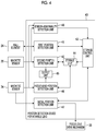
- FIG. 4 is a block diagram showing the schematic configuration of a position detection device 40 for a movable lens that is mounted on the lens device 2 shown in FIG. 1 .
- FIG. 5 is a diagram showing Lissajous curves based on output signals of magnetic sensors.
- FIG. 6 is a flowchart illustrating an operation for detecting the position of a zoom lens 21 by the position detection device 40 shown in FIG. 4 .
- FIG. 7 is a flowchart illustrating an operation for detecting the position of a focus lens 31 by the position detection device 40 shown in FIG. 4 .
- FIG. 1 is an external view showing the schematic structure of an imaging system according to an embodiment of the invention.
- the imaging system shown in FIG. 1 includes an imaging device 1 and a lens device 2 that is mounted on the imaging device 1 .
- the lens device 2 includes a housing 10 having a tubular shape, such as a cylindrical shape. Imaging lenses that include a zoom lens and a focus lens and a diaphragm device that can adjust an aperture are built in the housing 10 .
- a mount portion 3 is provided on the base portion of the housing 10 of the lens device 2 .
- a connection portion of the mount portion 3 is mounted on a lens mounting portion provided on the front portion of the imaging device 1 , so that the lens device 2 is fixed to the imaging device 1 .
- An imaging element is disposed on the optical axis of the lens device 2 in a state in which the lens device 2 is mounted on the imaging device 1 . Further, a subject is imaged through the imaging lenses of the lens device 2 by the imaging element. Output signals of the imaging element are processed by an image processing unit built in the imaging device 1 , so that various image data are generated.
- a photographer 5 carries the imaging device 1 on one's right shoulder and looks in a finder device 6 with, for example, a right eye. Further, while the photographer 5 grips a grip portion of the lens device 2 with a right hand 7 to fix the imaging device, the photographer 5 images a subject.
- a focus ring 8 which adjusts the focal position of the focus lens, is provided on the distal end side (subject side) of the lens device 2 so as to be rotationally movable around the outer periphery of the housing 10 .
- the photographer 5 rotates the focus ring 8 by an arbitrary angle with a hand, the photographer 5 can adjust a focus position.
- a zoom ring 9 which adjusts the zoom position of the zoom lens, is provided at the middle portion of the lens device 2 so as to be rotationally movable around the outer periphery of the housing 10 .
- the photographer 5 rotates the zoom ring 9 by an arbitrary angle with a hand, the photographer 5 can adjust zoom magnification.
- the lens device 2 is provided with an iris ring 11 , which is used to adjust the aperture of the diaphragm device, on the side of the zoom ring 9 close to the imaging device 1 .
- the iris ring 11 is provided so as to be rotationally movable around the outer periphery of the lens device 2 .
- FIG. 2 is a schematic diagram showing the internal configuration of the housing 10 of the lens device 2 shown in FIG. 1 near the zoom ring 9 .
- a rotating cylinder 10 a that is rotatable about an optical axis of the lens device 2 , a zoom lens 21 serving as a movable lens that is provided in the rotating cylinder 10 a and is movable in the direction of the optical axis, and a zoom lens holder 22 that holds the zoom lens 21 are provided in the housing 10 that is provided with the zoom ring 9 on the outer periphery thereof.
- the rotating cylinder 10 a includes a cam groove (not shown) that is used to convert the rotational motion of the rotating cylinder 10 a into the linear motion of the zoom lens holder 22 .
- a part of the zoom lens holder 22 is movably engaged with the cam groove. Accordingly, in a case in which the zoom ring 9 is operated and the zoom lens holder 22 is moved in the direction of the optical axis, the rotating cylinder 10 a is rotated about the optical axis with the movement of the zoom lens holder 22 .
- a magnet 23 is fixed to the zoom lens holder 22 .
- a Hall element 24 which coverts a magnetic field formed using Hall effect by the magnet 23 into electrical signals, is fixed outside the rotating cylinder 10 a in the housing 10 .
- signals output from the Hall element 24 are signals corresponding to the position of the zoom lens 21 .
- the Hall element 24 forms a first sensor that outputs a signal corresponding to the position of the zoom lens 21 .
- a variable resistor, a potentiometer, and the like other than the Hall element 24 can also be used as the first sensor.
- An annular magnetic recording member 20 which extends along the rotational direction of the rotating cylinder 10 a, is fixed to the outer periphery of the rotating cylinder 10 a.
- the magnetic recording member 20 is a member in which magnets having an S pole and an N pole are alternately magnetized along the rotational direction of the rotating cylinder 10 a.
- a magnetic sensor 25 is fixed and disposed outside the rotating cylinder 10 a at a position facing the magnetic recording member 20 in the housing 10 .
- the magnetic sensor 25 includes two magnetoresistive elements of which electric resistance is changed according to an applied magnetic field.
- the magnetic sensor 25 detects the magnetic signal of the magnetic recording member 20 , and outputs a sine wave signal and a cosine wave signal of which the phase is shifted from the phase of the sine wave signal by 90°.
- the magnetic recording member 20 is fixed to the rotating cylinder 10 a, and the rotation angle of the rotating cylinder 10 a corresponds to the moving distance of the zoom lens 21 in the direction of the optical axis. For this reason, the sine wave signals and the cosine wave signals, which are output from the magnetic sensor 25 , are signals corresponding to the moving distance of the zoom lens 21 in the direction of the optical axis.
- the magnetic sensor 25 forms a second sensor that outputs a signal corresponding to the moving distance of the zoom lens 21 in the direction of the optical axis in this way.
- the second sensor only has to be capable of detecting the moving distance of the zoom lens 21 in the direction of the optical axis, and a sensor other than the magnetic sensor may also be used as the second sensor.
- FIG. 3 is a schematic diagram showing the internal configuration of the housing 10 of the lens device 2 shown in FIG. 1 near the focus ring 8 .
- a rotating cylinder 10 b that is rotatable about the optical axis of the lens device 2 , a focus lens 31 serving as a movable lens that is provided in the rotating cylinder 10 b and is movable in the direction of the optical axis, and a focus lens holder 32 that holds the focus lens 31 are provided in the housing 10 that is provided with the focus ring 8 on the outer periphery thereof.
- the rotating cylinder 10 b is rotated in synchronization with the rotation of the focus ring 8 .
- the rotating cylinder 10 b includes a cam groove (not shown) that is used to convert the rotational motion of the rotating cylinder 10 b into the linear motion of the focus lens holder 32 .
- a part of the focus lens holder 32 is movably engaged with the cam groove.
- the rotating cylinder 10 b is rotated and the focus lens 31 is moved in the direction of the optical axis.
- a linear magnetic recording member 33 which extends along the moving direction of the focus lens 31 , is fixed to the focus lens holder 32 .
- the magnetic recording member 33 is a member in which magnets having an S pole and an N pole are alternately magnetized along the moving direction of the focus lens 31 .
- a magnetic sensor 34 is fixed and disposed outside the rotating cylinder 10 b at a position facing the magnetic recording member 33 in the housing 10 .
- the magnetic sensor 34 includes two magnetoresistive elements of which electric resistance is changed according to an applied magnetic field.
- the magnetic sensor 34 detects a magnetic signal from the magnetic recording member 33 , and outputs a sine wave signal and a cosine wave signal of which the phase is shifted from the phase of the sine wave signal by 90°.
- the magnetic recording member 33 is fixed to the focus lens 31 .
- the sine wave signals and the cosine wave signals which are output from the magnetic sensor 34 , are signals corresponding to the moving distance of the focus lens 31 in the direction of the optical axis.
- the magnetic sensor 34 forms a third sensor that outputs a signal corresponding to the moving distance of the focus lens 31 in the direction of the optical axis in this way.
- the third sensor only has to be capable of detecting the moving distance of the focus lens 31 in the direction of the optical axis, and a sensor other than the magnetic sensor may also be used as the third sensor.
- a focus lens drive mechanism 35 which is used to drive the focus lens 31 , is provided in the housing 10 .
- the focus lens drive mechanism 35 controls the position of the focus lens 31 in accordance with an instruction that is output from a position detection device to be described below.
- FIG. 4 is a block diagram showing the schematic configuration of a position detection device 40 for a movable lens that is mounted on the lens device 2 shown in FIG. 1 .
- the position detection device 40 includes a first position detection unit 41 , a second position detection unit 42 , a storage control unit 43 , a storage unit 44 , an output unit 45 , a focus lens-position detection unit 46 , an initial position detection unit 47 , and a sensor-abnormality detection unit 48 .
- the storage unit 44 may be provided outside the position detection device 40 .
- the position detection device 40 includes a processor as a main component.
- the first position detection unit 41 , the second position detection unit 42 , the storage control unit 43 , the output unit 45 , the focus lens-position detection unit 46 , the initial position detection unit 47 , and the sensor-abnormality detection unit 48 are functional blocks that are formed in a case in which the processor executes a position detection program.
- the position detection program is stored in a read only memory (ROM) that is built in, for example, the position detection device 40 .
- the ROM forms a non-transitory computer readable storage medium.
- the first position detection unit 41 detects the first position of the zoom lens 21 in the direction of the optical axis on the basis of signals output from the Hall element 24 , and inputs the detected first position to the storage control unit 43 .
- the first position detection unit 41 calculates an average value of a plurality of signals output from the Hall element 24 , and detects the first position on the basis of the average value. The calculation of the average value is performed to level deviations in the output of the Hall element 24 and to improve the accuracy of detection of the first position.
- the first position detection unit 41 performs the start control and the stop control of the Hall element 24 in accordance with an instruction of the storage control unit 43 .
- the initial position detection unit 47 controls the focus lens drive mechanism 35 , moves the focus lens 31 to one end of the movable range of the focus lens 31 , and then moves the focus lens 31 to the other end of the movable range.
- the initial position detection unit 47 detects the initial position of the focus lens 31 (the position of the focus lens 31 at the time of start of the lens device 2 ) on the basis of signals output from the magnetic sensor 34 during the movement of the focus lens 31 , and inputs the detected initial position to the storage control unit 43 .
- the movable range of the focus lens 31 is set to 50 cm and the initial position of the focus lens 31 is a position away from one end of the movable range by 10 cm is considered.
- the initial position detection unit 47 can detect that a moving distance between the initial position of the focus lens 31 and one end of the movable range (a first moving distance) is 10 cm, by output signals of the magnetic sensor 34 .
- the initial position detection unit 47 can detect a moving distance between one end and the other end of the movable range (a second moving distance) by the output signals of the magnetic sensor 34 . Accordingly, the initial position detection unit 47 can detect the initial position from a relationship between the first moving distance and the second moving distance.
- the initial position detection unit 47 detects the initial position at the time of start of the lens device 2 and in a case in which a predetermined condition is satisfied, and does not operate in other cases.
- the storage control unit 43 makes the first position detection unit 41 detect the first position and stores the first position in the storage unit 44 formed of a storage medium, such as a random access memory (RAM), at the time of start of the lens device 2 that is a timing determined in advance.
- a storage medium such as a random access memory (RAM)
- the storage control unit 43 stores the first position in the storage unit 44 at the time of start of the lens device 2 , the storage control unit 43 updates the first position stored in the storage unit 44 in a case in which a predetermined condition is satisfied.
- the storage control unit 43 stores the initial position, which is detected by the initial position detection unit 47 , in the storage unit 44 .
- the second position detection unit 42 detects the second position of the zoom lens 21 in the direction of the optical axis on the basis of signals output from the magnetic sensor 25 and the most recent first position stored in the storage unit 44 .
- the second position detection unit 42 uses the most recent first position stored in the storage unit 44 as a reference position, calculates the moving distance of the zoom lens 21 from the reference position on the basis of signals output from the magnetic sensor 25 , and detects a position, which is moved from the reference position by this moving distance, as a second position.
- the focus lens-position detection unit 46 detects the position of the focus lens 31 on the basis of the most recent initial position stored in the storage unit 44 and signals output from the magnetic sensor 34 .
- the focus lens-position detection unit 46 uses the most recent initial position stored in the storage unit 44 as a reference position, calculates the moving distance of the focus lens 31 from the reference position on the basis of signals output from the magnetic sensor 34 , and detects a position, which is moved from the reference position by this moving distance, as the position of the focus lens 31 .
- the output unit 45 notifies a user of the current position information of the zoom lens 21 by outputting the second position, which is detected by the second position detection unit 42 , to a display unit or the like of the lens device 2 as the current position information of the zoom lens 21 or outputs the second position to the imaging device 1 .
- the output unit 45 outputs the position of the focus lens 31 , which is detected by the focus lens-position detection unit 46 , to the display unit or the like of the lens device 2 as the current position information of the focus lens 31 , or outputs the position of the focus lens 31 to the imaging device 1 .
- the sensor-abnormality detection unit 48 functions as a second sensor-state detection unit that detects whether the output signal of the magnetic sensor 25 is in a normal state or an abnormal state, and a third sensor-state detection unit that detects whether the output signal of the magnetic sensor 34 is in a normal state or an abnormal state.
- the sensor-abnormality detection unit 48 generates a determination value that is used to determine the state of an output signal of the magnetic sensor 25 on the basis of output signals of the magnetic sensor 25 , and detects whether the output signal of the magnetic sensor 25 is in an abnormal state or a normal state by the comparison between the determination value and an abnormality-determination threshold value.
- the sensor-abnormality detection unit 48 generates a determination value that is used to determine the state of an output signal of the magnetic sensor 34 on the basis of output signals of the magnetic sensor 34 , and detects whether the output signal of the magnetic sensor 34 is in an abnormal state or a normal state by the comparison between the determination value and an abnormality-determination threshold value.
- FIG. 5 is a diagram showing Lissajous curves based on the output signals of the magnetic sensors.
- a curve R 1 shown in FIG. 5 is a Lissajous curve based on the output signal of the magnetic sensor 25 in a case in which the output signal of the magnetic sensor 25 is in a normal state.
- a curve R 2 shown in FIG. 5 is a Lissajous curve based on the output signal of the magnetic sensor 25 in a case in which the output signal of the magnetic sensor 25 is in an abnormal state.
- the curve R 1 is a circle having a radius r 1 and having a center at a point O, which is determined in advance, as shown in FIG. 5 .
- the Lissajous curve becomes the curve R 2 and the center and radius of the Lissajous curve are changed from those of the curve R 1 .
- a difference between the square value of a distance, which is calculated by Equation (1), and the square value of the radius r 1 is reduced in a case in which the output signal of the magnetic sensor 25 is in a normal state (a state in which the magnetic sensor 25 operates as designed), and is increased in a case in which the output signal of the magnetic sensor 25 is in an abnormal state.
- the square value of a distance r 2 between the point O and the curve R 2 is sufficiently larger than the square value of the radius r 1 .
- the sensor-abnormality detection unit 48 calculates a difference between the square value of a distance, which is calculated by Equation (1), and the square value of the radius r 1 , which is determined in advance, as the determination value.
- the sensor-abnormality detection unit 48 detects that the output signal of the magnetic sensor 25 is in an abnormal state in a case in which the determination value exceeds the abnormality-determination threshold value, and detects that the output signal of the magnetic sensor 25 is in a normal state in a case in which the determination value is equal to or smaller than the abnormality-determination threshold value.
- Equation (1) a difference between the square value of a distance, which is calculated by Equation (1), and the square value of the radius r 1 , which is determined in advance, has been described as the determination value, but the square value of a distance calculated by Equation (1) may be used as the determination value.
- a predetermined range for example, the range of 0.7 times to 1.3 times
- the abnormality-determination threshold value a predetermined range (for example, the range of 0.7 times to 1.3 times) of the square value of the radius r 1 , which is determined in advance, is referred to as the abnormality-determination threshold value.
- the sensor-abnormality detection unit 48 determines that the output signal of the magnetic sensor 25 is in a normal state in a case in which the square value of a distance calculated by Equation (1) is in this predetermined range, and detects that the output signal of the magnetic sensor 25 is in an abnormal state in a case in which the square value of a distance calculated by Equation (1) is not in this predetermined range.
- the sensor-abnormality detection unit 48 also detects whether the output signal of the magnetic sensor 34 is in an abnormal state or a normal state in the same manner as described above.
- FIG. 6 is a flowchart illustrating an operation for detecting the position of the zoom lens 21 by the position detection device 40 shown in FIG. 4 .
- the storage control unit 43 starts the Hall element 24 through the first position detection unit 41 .
- the first position detection unit 41 detects the first position of the zoom lens 21 on the basis of the signals output from the Hall element 24 , and the power source of the Hall element 24 is turned off after the detection of the first position.
- the storage control unit 43 stores the first position in the storage unit 44 .
- the second position detection unit 42 detects the second position of the zoom lens 21 on the basis of the first position stored in the storage unit 44 and the signals output from the magnetic sensor 25 . Then, in a case in which the signal output from the magnetic sensor 25 is changed, the second position is changed.
- the sensor-abnormality detection unit 48 calculates the determination value on the basis of the output signals of the magnetic sensor 25 and determines whether or not the calculated determination value exceeds the abnormality-determination threshold value (Step S 1 ).
- the abnormality-determination threshold value is expressed by a numerical value range
- a state in which the determination value is not in the numerical value range is treated as a state in which the determination value exceeds the abnormality-determination threshold value and a state in which the determination value is in the numerical value range is treated as a state in which the determination value is equal to or smaller than the abnormality-determination threshold value.
- Step S 1 if the determination value is equal to or smaller than the abnormality-determination threshold value (NO in Step S 1 ), the determination of Step S 1 is repeated.
- Step S 2 the sensor-abnormality detection unit 48 determines whether or not the determination value is equal to or smaller than the abnormality-determination threshold value (Step S 2 ).
- Step S 2 If the determination value exceeds the abnormality-determination threshold value (NO in Step S 2 ), the processing of Step S 2 is repeated. If the determination value is equal to or smaller than the abnormality-determination threshold value (YES in Step S 2 ), the processing of Step S 3 is performed.
- Step S 3 the storage control unit 43 starts the Hall element 24 through the first position detection unit 41 and instructs the first position detection unit 41 to perform first detection.
- the average number of signals output from the Hall element 24 is set to m (m is a natural number of 2 or more).
- the first position detection unit 41 calculates an average value of m signals output from the Hall element 24 and detects the first position of the zoom lens 21 on the basis of the average value (Step S 3 ).
- the storage control unit 43 determines whether or not a position shift state in which a difference (absolute value) between the first position detected in Step S 3 and the second position detected at the current point of time by the second position detection unit 42 is equal to or larger than a position threshold value TH 1 is made (Step S 4 ).
- Step S 4 If the storage control unit 43 determines that the position shift state is made (YES in Step S 4 ), the storage control unit 43 stores the first position, which is detected in Step S 3 , in the storage unit 44 (Step S 5 ).
- a second position is detected on the basis of the most recent first position and the output signals of the magnetic sensor 25 by the second position detection unit 42 .
- Step S 4 If the storage control unit 43 determines that the position shift state is not made (NO in Step S 4 ), the storage control unit 43 performs the processing of Step S 6 without storing the first position, which is detected in Step S 3 , in the storage unit 44 .
- Step S 6 the storage control unit 43 determines whether or not the zoom lens 21 is being moved (Step S 6 ).
- the storage control unit 43 determines that the zoom lens 21 is stopped. In a case in which the moving distance of the zoom lens 21 is equal to or larger than the moving-distance threshold value, the storage control unit 43 determines that the zoom lens 21 is being moved.
- the storage control unit 43 If the storage control unit 43 is in a first case in which the storage control unit 43 determines that the zoom lens 21 is being moved (YES in Step S 6 ), the storage control unit 43 instructs the first position detection unit 41 to detect the first position. In this instruction, the average number of signals output from the Hall element 24 is set to m.
- the first position detection unit 41 calculates an average value of m signals output from the Hall element 24 and detects the first position of the zoom lens 21 on the basis of the average value (Step S 7 ).
- the storage control unit 43 determines whether or not a position shift state in which a difference (absolute value) between the first position detected in Step S 7 and the second position detected at the current point of time by the second position detection unit 42 is equal to or larger than the position threshold value TH 1 is made (Step S 8 ).
- Step S 8 If the storage control unit 43 determines that the position shift state is made (YES in Step S 8 ), the storage control unit 43 stores the first position, which is detected in Step S 7 , in the storage unit 44 (Step S 9 ).
- a second position is detected on the basis of the most recent first position and the output signals of the magnetic sensor 25 by the second position detection unit 42 .
- Step S 8 If the storage control unit 43 determines that the position shift state is not made (NO in Step S 8 ), the storage control unit 43 returns to the processing of Step S 6 without storing the first position, which is detected in Step S 7 , in the storage unit 44 .
- the storage control unit 43 instructs the first position detection unit 41 to detect the first position.
- the average number of signals output from the Hall element 24 is set to n (n is a natural number larger than m).
- the first position detection unit 41 calculates an average value of n signals output from the Hall element 24 and detects the first position of the zoom lens 21 on the basis of the average value (Step S 10 ).
- the storage control unit 43 determines whether or not a position shift state in which a difference (absolute value) between the first position detected in Step S 10 and the second position detected at the current point of time by the second position detection unit 42 is equal to or larger than a position threshold value TH 2 is made (Step S 11 ).
- the position threshold value TH 2 is a value smaller than the position threshold value TH 1 .
- Step S 11 If the storage control unit 43 determines that the position shift state is made (YES in Step S 11 ), the storage control unit 43 stores the first position, which is detected in Step S 10 , in the storage unit 44 (Step S 12 ).
- a second position is detected on the basis of the most recent first position and the output signals of the magnetic sensor 25 by the second position detection unit 42 .
- Step S 11 If the storage control unit 43 determines that the position shift state is not made (NO in Step S 11 ), the storage control unit 43 turns the power source of the Hall element 24 off without storing the first position, which is detected in Step S 10 , in the storage unit 44 . After that, processing returns to Step S 1 .
- the Hall element 24 is started and the first position is detected by the first position detection unit 41 .
- the first position stored in the storage unit 44 is updated with new information.
- the Hall element 24 Since the Hall element 24 is started and the first position detection unit 41 detects the first position in the abnormality-recovery state in this way, the first position stored in the storage unit 44 can be updated. For this reason, an error of the second position of the zoom lens 21 , which is caused by the occurrence of abnormality on the output signal of the magnetic sensor 25 , can be corrected and can return to a correct value.
- the highly accurate detection of the position of the zoom lens 21 can be continued even in a case in which abnormality occurs on the output of the magnetic sensor 25 due to a strong electric field or the like, a user can continue intended imaging.
- the position detection device 40 performs the determination of whether or not the position shift state is made in Step S 4 of FIG. 6 , the position detection device 40 further performs the determination of whether or not the position shift state is made at least once.
- the determination of whether or not the position shift state is made is performed at least twice in this way, it is possible to flexibly respond to a change in a situation in the abnormality-recovery state and to improve the accuracy of detection of the second position.
- Step S 4 determination is made again in Step S 8 and the first position is updated as necessary.
- the first position stored in the storage unit 44 can be updated during the movement of the zoom lens 21 in this way, the accuracy of detection of the second position of the zoom lens 21 can be improved even in a case in which the zoom lens 21 is moved.
- Step S 4 determination is made again in Step S 11 and the first position is updated as necessary.
- the first position stored in the storage unit 44 can be updated in a state in which the zoom lens 21 is stopped in this way, the accuracy of detection of the second position of the zoom lens 21 can be improved even in a case in which the zoom lens 21 is moved.
- the position threshold value TH 1 used in the determination of Step S 8 is larger than the position threshold value TH 2 used in the determination of Step S 11 . For this reason, even though a difference between the first and second positions in Step S 8 has the same value as that in Step S 11 , the storage control unit 43 is not likely to determine that the position shift state is made in Step S 8 .
- the first position stored in the storage unit 44 is not likely to be updated during the movement of the zoom lens 21 in comparison with that during the stop of the zoom lens 21 , the variation of the second position during a zoom operation can be suppressed. As a result, the quality of an image to be taken during a zoom operation can be improved.
- the number (m in the above description) of output signals of the magnetic sensor 25 from which the average value is calculated, which is used to detect the first position in Step S 3 is smaller than the number (n in the above description) of output signals of the magnetic sensor 25 from which the average value is calculated, which is used to detect the first position in Step S 10 .
- Step S 3 It is possible to make processing speed and the accuracy of detection be compatible with each other by reducing the average number in Step S 3 to give priority to processing speed and increasing the average number in Step S 10 to give priority to the accuracy of detection of the second position in this way.
- the position detection device 40 since the Hall element 24 of which the power consumption is larger than the power consumption of the magnetic sensor 25 is started only at the time of start of the lens device 2 and in the abnormality-recovery state, it is possible to improve the accuracy of detection of the second position while reducing power consumption.
- Step S 4 may be omitted in the flowchart of FIG. 6 so that the processing of Step S 5 is performed after Step S 3 . In this case, the processing load of the position detection device 40 can be reduced.
- Step S 8 may be omitted so that Step S 9 is performed after Step S 7 .
- Step S 11 may be omitted so that Step S 12 is performed after Step S 10 .
- n and the m may be set as the same value, and the position threshold values TH 1 and TH 2 may be set as the same value.
- FIG. 7 is a flowchart illustrating an operation for detecting the position of the focus lens 31 by the position detection device 40 shown in FIG. 4 .
- the initial position detection unit 47 controls the focus lens drive mechanism 35 , moves the focus lens 31 to one end of the movable range from the current position, and then moves the focus lens 31 to the other end from one end of the movable range.
- the initial position detection unit 47 detects the initial position of the focus lens 31 on the basis of signals output from the magnetic sensor 34 during the movement of the focus lens 31 .
- the detected initial position is stored in the storage unit 44 by the storage control unit 43 (Step S 21 ).
- the focus lens-position detection unit 46 detects the position of the focus lens 31 on the basis of the initial position stored in the storage unit 44 and signals output from the magnetic sensor 34 (Step S 22 ). Then, in a case in which the signal output from the magnetic sensor 34 is changed, the position of the focus lens 31 to be detected is changed.
- the sensor-abnormality detection unit 48 calculates the determination value on the basis of the output signals of the magnetic sensor 34 and determines whether or not the calculated determination value exceeds the abnormality-determination threshold value (Step S 23 ). If the determination value is equal to or smaller than the abnormality-determination threshold value (NO in Step S 23 ), the determination of Step S 23 is repeated.
- the sensor-abnormality detection unit 48 determines whether or not the determination value is equal to or smaller than the abnormality-determination threshold value (Step S 24 ).
- Step S 24 If the determination value exceeds the abnormality-determination threshold value (NO in Step S 24 ), the processing of Step S 24 is repeated. If the determination value is equal to or smaller than the abnormality-determination threshold value (YES in Step S 24 ), the processing of Step S 25 is performed.
- Step S 25 the initial position detection unit 47 controls the focus lens drive mechanism 35 , moves the focus lens 31 to one end of the movable range from the current position, and then moves the focus lens 31 to the other end from one end of the movable range.
- the initial position detection unit 47 detects the initial position of the focus lens 31 again on the basis of signals output from the magnetic sensor 34 during the movement of the focus lens 31 .
- the detected initial position is stored in the storage unit 44 by the storage control unit 43 . Processing returns to Step S 22 after Step S 25 .
- the position detection device 40 in an abnormality-recovery state of the magnetic sensor 34 in which the output signal of the magnetic sensor 34 enters an abnormal state and then returns to a normal state, the initial position of the focus lens 31 is detected again and the initial position stored in the storage unit 44 is updated. Then, the position of the focus lens is detected on the basis of the updated initial position and output signals of the magnetic sensor 34 by the focus lens-position detection unit 46 .
- the highly accurate detection of the position of the focus lens 31 can be performed even in a case in which abnormality occurs on the output of the magnetic sensor 34 due to a strong electric field or the like, a user can continue intended imaging.
- the sensor-abnormality detection unit 48 which has been described above, detects whether each of the magnetic sensors 25 and 34 is in an abnormal state or a normal state by the comparison between the determination value and the abnormality-determination threshold value.
- values, which are experimentally obtained from every lens device 2 may be stored in an internal memory of the position detection device as the abnormality-determination threshold value.
- the square value of the radius of a Lissajous curve based on signals output from the magnetic sensor 25 and the square value of the radius of a Lissajous curve based on signals output from the magnetic sensor 34 are calculated in a first state in which the lens device 2 is under an environment where radio waves are not applied to the magnetic sensors 25 and 34 .
- the square value of the radius of a Lissajous curve based on signals output from the magnetic sensor 25 and the square value of the radius of a Lissajous curve based on signals output from the magnetic sensor 34 are calculated in a second state in which already-known radio waves are applied to the magnetic sensors 25 and 34 .
- an abnormality-determination threshold value is determined from the square value that is obtained from the respective magnetic sensors 25 and 34 in the first state and the square value that is obtained from the respective magnetic sensors 25 and 34 in the second state, and the determined abnormality-determination threshold value is stored in the internal memory.
- the detection of the abnormal state of the magnetic sensor can be accurately performed even in a case in which the degree of influence caused by the radio waves varies in each lens device 2 .
- the abnormality-determination threshold value may be stored in the lens device 2 as a fixed value that is determined in advance, but the sensor-abnormality detection unit 48 may have a function to generate an abnormality-determination threshold value on the basis of the output signals of the magnetic sensor 25 and the output signals of the magnetic sensor 34 . In this case, the sensor-abnormality detection unit 48 functions as an abnormality-determination-threshold-value generation unit.
- the sensor-abnormality detection unit 48 acquires sine wave signals and cosine wave signals, which are output from the magnetic sensor 25 , corresponding to at least one cycle during the start of the lens device 2 .
- the sensor-abnormality detection unit 48 determines that the output signal of the magnetic sensor 25 is in a normal state in a case in which the deviation of the square values of Equation (1) of all phases of one cycle is equal to or smaller than a predetermined value, and calculates an average value of the square values in this normal state.
- the sensor-abnormality detection unit 48 stores a value, which is the sum of the calculated average value and a predetermined value of 1 or less, or the range of ⁇ a predetermined percentage of the calculated average value in the internal memory as an abnormality-determination threshold value.
- the amplitudes of a sine wave signal and a cosine wave signal, which are output from the magnetic sensor 25 vary according to an individual difference of the magnetic sensor. For this reason, the sensor-abnormality detection unit 48 sets the predetermined value and the value of the predetermined percentage to values corresponding to the amplitudes of the sine wave signal and the cosine wave signal that are output from the magnetic sensor 25 in the normal state.
- the detection of an abnormal state can be accurately performed. Only the magnetic sensor 25 has been described here, but it is preferable that the sensor-abnormality detection unit 48 also generates an abnormality-determination threshold value in regard to the magnetic sensor 34 .
- the sensor-abnormality detection unit 48 may have a function to correct the abnormality-determination threshold value, which is stored in the internal memory, in order to further improve the accuracy of the abnormality-determination threshold value that is generated in this way.
- the sensor-abnormality detection unit 48 corrects the abnormality-determination threshold value, which is stored in the internal memory, on the basis of a difference between the first position that is detected first in the abnormality-recovery state of the magnetic sensor 25 by the first position detection unit 41 and the second position that is detected by the second position detection unit 42 immediately before the abnormality-recovery state.
- the abnormality-determination threshold value is a value where the state of the output signal of the magnetic sensor 25 is likely to be determined as an abnormal state.
- the sensor-abnormality detection unit 48 determines whether or not a difference between the first position detected in Step S 3 and the second position detected by the second position detection unit 42 immediately before the determination of “YES” is made in Step S 2 is equal to or small than a threshold value.
- an abnormality-determination threshold value is one numerical value in a case in which the difference is equal to or smaller than the threshold value
- the sensor-abnormality detection unit 48 stores a value, which is increased (for example, 1.1 times) from the abnormality-determination threshold value, in the internal memory as a corrected abnormality-determination threshold value.
- the sensor-abnormality detection unit 48 stores a value, which is obtained by multiplying the upper limit of the numerical value range by, for example, 1.1, and a value, which is obtained by multiplying the lower limit thereof by, for example, 0.9, as a corrected abnormality-determination threshold value.
- the abnormality-determination threshold value is corrected in this way, it is possible to prevent an operation, which is subsequent to Step S 1 shown in FIG. 6 , from being excessively performed. Accordingly, it is possible to improve the processing efficiency of the position detection device 40 .
- “Immediately before the abnormality-recovery state” means an arbitrary timing in a period between the point of time where the sensor-abnormality detection unit 48 detects that the output signal of the magnetic sensor is an abnormal state and the point of time where the sensor-abnormality detection unit 48 detects that the output signal of the magnetic sensor is a normal state (excluding the latter point of time).
- the sensor-abnormality detection unit 48 generates an abnormality-determination threshold value by the above-mentioned method, generates a temporary abnormality-determination threshold value, which is reduced from the generated abnormality-determination threshold value, and stores the temporary abnormality-determination threshold value in the internal memory.
- the temporary abnormality-determination threshold value is a value that is reduced from the numerical value.
- the temporary abnormality-determination threshold value is in a range between a value that is increased from the lower limit of the numerical value range and a value that is reduced from the upper limit of the numerical value range.
- the sensor-abnormality detection unit 48 calculates a determination value on the basis of the output signals of the magnetic sensor 25 , and determines whether or not the calculated determination value exceeds the temporary abnormality-determination threshold value and is equal to or smaller than the abnormality-determination threshold value.
- the fact that the determination value exceeds the temporary abnormality-determination threshold value means that the determination value is not in a numerical value range in a case in which the temporary abnormality-determination threshold value is expressed by the numerical value range.
- the fact that the determination value is equal to or smaller than the abnormality-determination threshold value means that the determination value is in a numerical value range in a case in which the abnormality-determination threshold value is expressed by the numerical value range.
- the sensor-abnormality detection unit 48 determines that the calculated determination value exceeds the temporary abnormality-determination threshold value and is equal to or smaller than the abnormality-determination threshold value, the sensor-abnormality detection unit 48 calculates a difference between the most recent two second positions detected by the second position detection unit 42 as a variation of the second position.
- the sensor-abnormality detection unit 48 deletes the abnormality-determination threshold value of the internal memory and sets the temporary abnormality-determination threshold value as an abnormality-determination threshold value.
- the sensor-abnormality detection unit 48 makes the abnormality-determination threshold value of the internal memory be effective as it is.
- a state in which it is detected that the output signal of the magnetic sensor 25 is in a normal state although the variation of the second position exceeds the variation threshold value means that the abnormality-determination threshold value is a value where the state of the output signal of the magnetic sensor 25 is likely to be determined as a normal state.
- a method of correcting an abnormality-determination threshold value, which is used to detect the abnormal state of the output signal of the magnetic sensor 25 has been described in the above description, but a method of correcting an abnormality-determination threshold value, which is used to detect the abnormal state of the output signal of the magnetic sensor 34 , will be described below.
- the sensor-abnormality detection unit 48 corrects the abnormality-determination threshold value, which is stored in the internal memory, on the basis of a difference between the initial position that is detected first in the abnormality-recovery state of the magnetic sensor 34 by the initial position detection unit 47 and the position of the focus lens that is detected by the focus lens-position detection unit 46 immediately before the abnormality-recovery state of the magnetic sensor 34 .
- the abnormality-determination threshold value is a value where the state of the output signal of the magnetic sensor 34 is likely to be determined as an abnormal state.
- the sensor-abnormality detection unit 48 determines whether or not a difference between the initial position detected in Step S 25 and the position of the focus lens detected immediately before the determination of “YES” is made in Step S 24 is equal to or small than a threshold value.
- an abnormality-determination threshold value is one numerical value in a case in which the difference is equal to or smaller than the threshold value
- the sensor-abnormality detection unit 48 stores a value, which is increased (for example, 1.1 times) from the abnormality-determination threshold value, in the internal memory as a corrected abnormality-determination threshold value.
- the sensor-abnormality detection unit 48 stores a value, which is obtained by multiplying the upper limit of the numerical value range by, for example, 1.1, and a value, which is obtained by multiplying the lower limit thereof by, for example, 0.9, as a corrected abnormality-determination threshold value.
- the abnormality-determination threshold value is corrected in this way, it is possible to prevent an operation, which is subsequent to Step S 24 shown in FIG. 7 , from being excessively performed. Accordingly, it is possible to improve the processing efficiency of the position detection device 40 .
- “Immediately before the abnormality-recovery state of the magnetic sensor 34 ” means an arbitrary timing in a period between the point of time where the sensor-abnormality detection unit 48 detects that the output signal of the magnetic sensor 34 is an abnormal state and the point of time where the sensor-abnormality detection unit 48 detects that the output signal of the magnetic sensor 34 is a normal state (excluding the latter point of time).
- the sensor-abnormality detection unit 48 generates an abnormality-determination threshold value by the above-mentioned method, generates a temporary abnormality-determination threshold value, which is reduced from the generated abnormality-determination threshold value, and stores the temporary abnormality-determination threshold value in the internal memory.
- the temporary abnormality-determination threshold value is a value that is reduced from this numerical value.
- the temporary abnormality-determination threshold value is in a range between a value that is reduced from the lower limit of the numerical value range and a value that is reduced from the upper limit of the numerical value range.
- the sensor-abnormality detection unit 48 calculates a determination value on the basis of the output signals of the magnetic sensor 34 , and determines whether or not the calculated determination value exceeds the temporary abnormality-determination threshold value and is equal to or smaller than the abnormality-determination threshold value.
- the sensor-abnormality detection unit 48 determines that the calculated determination value exceeds the temporary abnormality-determination threshold value and is equal to or smaller than the abnormality-determination threshold value, the sensor-abnormality detection unit 48 calculates a difference between the most recent two positions of the focus lens detected by the focus lens-position detection unit 46 as a variation of the position of the focus lens.
- the sensor-abnormality detection unit 48 deletes the abnormality-determination threshold value of the internal memory and sets the temporary abnormality-determination threshold value as an abnormality-determination threshold value.
- the sensor-abnormality detection unit 48 makes the abnormality-determination threshold value of the internal memory be effective just as it is.
- a state in which it is detected that the output signal of the magnetic sensor 34 is in a normal state although the variation of the position of the focus lens exceeds the variation threshold value means that the abnormality-determination threshold value is a value where the state of the output signal of the magnetic sensor 34 is likely to be determined as a normal state.
- the lens device 2 may be adapted so that the zoom lens 21 is changed to the focus lens 31 and the focus lens 31 is changed to the zoom lens 21 . Further, the lens device 2 may be adapted to detect the position of the focus lens 31 by continuing to use the initial position, which is detected at the time of start of the lens device 2 by the initial position detection unit 47 , during the start of the lens device 2 .
- the lens device 2 has been described as a lens device for business use, but can also be applied as a lens device that is to be detachably mounted on a digital camera serving as an imaging device.
- the disclosed position detection device for a movable lens comprises a first position detection unit that detects a first position of a movable lens in a direction of an optical axis on the basis of a signal output from a first sensor outputting a signal corresponding to the position of the movable lens in the direction of the optical axis, a storage control unit that stores the first position detected by the first position detection unit in a storage unit, a second position detection unit that detects a second position of the movable lens in the direction of the optical axis on the basis of a signal output from a second sensor outputting a signal corresponding to a moving distance of the movable lens in the direction of the optical axis and the most recent first position stored in the storage unit, an output unit that outputs the second position detected by the second position detection unit, and a second sensor-state detection unit that detects whether the output signal of the second sensor is in a normal state or an abnormal state.
- the first position detection unit detects the first position on the basis of a signal output from the first sensor at a timing determined in advance, and detects the first position again on the basis of a signal output from the first sensor in an abnormality-recovery state in which the second sensor-state detection unit detects that the output signal of the second sensor is in the abnormal state and then detects that the output signal of the second sensor is in the normal state after the first position is stored in the storage unit.
- the storage control unit determines whether or not a position shift state in which a difference between the first position detected by the first position detection unit and the second position detected by the second position detection unit is equal to or larger than a position threshold value is made in the abnormality-recovery state, and stores the first position detected by the first position detection unit in the storage unit in a case in which the position shift state is made.
- the storage control unit performs the determination at least once.
- the movable lens includes a zoom lens
- the storage control unit determines whether or not the position shift state is made in the abnormality-recovery state, repeatedly performs the determination until the moving distance of the zoom lens is smaller than a moving-distance threshold value in a first case in which the moving distance of the zoom lens is equal to or larger than the moving-distance threshold value, and performs the determination once in a second case in which the moving distance of the zoom lens is smaller than the moving-distance threshold value.
- the position threshold value which is used for the determination to be performed in the first case, is larger than the position threshold value that is used for the determination to be performed in the second case.
- the first position detection unit detects the first position on the basis of an average value of signals output from the first sensor, and the number of signals output from the first sensor from which the average value is calculated in a case in which the first position used in the determination to be performed in the second case is to be detected is larger than the number of signals output from the first sensor from which the average value is calculated in a case in which the first position used in the determination to be performed first in the abnormality-recovery state is to be detected.
- the second sensor-state detection unit In the disclosed position detection device for a movable lens, the second sensor-state detection unit generates a determination value that is used to determine the state of the output signal of the second sensor on the basis of the output signal of the second sensor, and detects whether the output signal of the second sensor is in the abnormal state or the normal state by comparison between the determination value and an abnormality-determination threshold value.
- the position detection device for a movable lens further comprises an abnormality-determination-threshold-value generation unit that generates the abnormality-determination threshold value on the basis of the output signal of the second sensor.
- the second sensor-state detection unit corrects the abnormality-determination threshold value on the basis of a difference between the position detected by the first position detection unit in the abnormality-recovery state and the second position detected by the second position detection unit immediately before the abnormality-recovery state.
- the second sensor-state detection unit sets a temporary abnormality-determination threshold value as the abnormality-determination threshold value in a case in which a variation of the second position detected by the second position detection unit exceeds a variation threshold value in a state in which the determination value exceeds the temporary abnormality-determination threshold value smaller than the abnormality-determination threshold value and is equal to or smaller than the abnormality-determination threshold value.
- the movable lens is a zoom lens.
- the position detection device for a movable lens further comprises: a third sensor-state detection unit that detects whether an output signal of a third sensor outputting a signal corresponding to a moving distance of a focus lens, which is a movable lens different from the zoom lens, is in the normal state or the abnormal state; an initial position detection unit that detects an initial position of the focus lens on the basis of a signal output from the third sensor while moving the focus lens to one end of a movable range of the focus lens from a current position and moving the focus lens to the other end of the movable range from the one end of the movable range; a focus lens-position detection unit that detects the position of the focus lens on the basis of the initial position detected by the initial position detection unit and a signal output from the third sensor.
- the initial position detection unit After the initial position detection unit detects the initial position at a timing determined in advance, the initial position detection unit detects the initial position again in a third sensor abnormality-recovery state in which the third sensor-state detection unit detects that the output signal of the third sensor is in the abnormal state and then detects that the output signal of the third sensor is in the normal state.
- the third sensor-state detection unit In the disclosed position detection device for a movable lens, the third sensor-state detection unit generates a determination value that is used to determine the state of the output signal of the third sensor on the basis of the output signal of the third sensor, and detects whether the output signal of the third sensor is in the abnormal state or the normal state by comparison between the determination value and an abnormality-determination threshold value.
- the position detection device for a movable lens further comprises an abnormality-determination-threshold-value generation unit that generates the abnormality-determination threshold value on the basis of the output signal of the third sensor.
- the third sensor-state detection unit corrects the abnormality-determination threshold value on the basis of a difference between the initial position detected by the initial position detection unit in the third sensor abnormality-recovery state and the position detected by the focus lens-position detection unit immediately before the third sensor abnormality-recovery state.
- the third sensor-state detection unit sets a temporary abnormality-determination threshold value as the abnormality-determination threshold value in a case in which a variation of the position of the focus lens detected by the focus lens-position detection unit exceeds a variation threshold value in a state in which the determination value exceeds the temporary abnormality-determination threshold value smaller than the abnormality-determination threshold value and is equal to or smaller than the abnormality-determination threshold value.
- the second sensor is a sensor including a magnetoresistive element.
- each of the second sensor and the third sensor is a sensor including a magnetoresistive element.
- a disclosed lens device of the invention comprises the position detection device and a movable lens of which the position is to be detected by the position detection device.
- a disclosed imaging device comprises the position detection device and an imaging element that images a subject through a movable lens of which the position is to be detected by the position detection device.
- a disclosed position detection method for a movable lens comprises a first position detection step of detecting a first position of a movable lens in a direction of an optical axis on the basis of a signal output from a first sensor outputting a signal corresponding to the position of the movable lens in the direction of the optical axis, a storage control step of storing the first position detected in the first position detection step in a storage unit, a second position detection step of detecting a second position of the movable lens in the direction of the optical axis on the basis of a signal output from a second sensor outputting a signal corresponding to a moving distance of the movable lens in the direction of the optical axis and the most recent first position stored in the storage unit, an output step of outputting the second position detected in the second position detection step, and a second sensor-state detection step of detecting whether the output signal of the second sensor is in a normal state or an abnormal state.
- the first position detection step the first position is detected on the basis of a signal output from the first sensor at a timing determined in advance, and the first position is detected again on the basis of a signal output from the first sensor in an abnormality-recovery state in which in the second sensor-state detection step, it is detected that the output signal of the second sensor is in the abnormal state and it is then detected that the output signal of the second sensor is the a normal state after the first position is stored in the storage unit.
- the storage control step it is determined whether or not a position shift state in which a difference between the first position detected in the first position detection step and the second position detected in the second position detection step is equal to or larger than a position threshold value is made in the abnormality-recovery state, and the first position detected in the first position detection step is stored in the storage unit in a case in which the position shift state is made.
- the determination is performed at least once.
- the movable lens includes a zoom lens.
- determination of whether or not the position shift state is made in the abnormality-recovery state is performed, the determination is repeatedly performed until the moving distance of the zoom lens is smaller than a moving-distance threshold value in a first case in which the moving distance of the zoom lens is equal to or larger than the moving-distance threshold value, and the determination is performed once in a second case in which the moving distance of the zoom lens is smaller than the moving-distance threshold value.
- the position threshold value which is used for the determination to be performed in the first case, is larger than the position threshold value that is used for the determination to be performed in the second case.
- the first position is detected on the basis of an average value of signals output from the first sensor, and the number of signals output from the first sensor from which the average value is calculated in a case in which the first position used in the determination to be performed in the second case is to be detected is larger than the number of signals output from the first sensor from which the average value is calculated in a case in which the first position used in the determination to be performed first in the abnormality-recovery state is to be detected.
- a determination value that is used to determine the state of the output signal of the second sensor is generated on the basis of the output signal of the second sensor, and whether the output signal of the second sensor is in the abnormal state or the normal state is detected by comparison between the determination value and an abnormality-determination threshold value.
- the position detection method for a movable lens further comprises an abnormality-determination-threshold-value generation step of generating the abnormality-determination threshold value on the basis of the output signal of the second sensor.
- the abnormality-determination threshold value is corrected on the basis of a difference between the first position detected in the initial position detection step in the abnormality-recovery state and the second position detected in the second position detection step immediately before the abnormality-recovery state.
- a temporary abnormality-determination threshold value is set as the abnormality-determination threshold value in a case in which a variation of the second position detected in the second position detection step exceeds a variation threshold value in a state in which the determination value exceeds the temporary abnormality-determination threshold value smaller than the abnormality-determination threshold value and is equal to or smaller than the abnormality-determination threshold value.
- the movable lens is a zoom lens.
- the position detection method for a movable lens further comprises: a third sensor-state detection step of detecting whether an output signal of a third sensor outputting a signal corresponding to a moving distance of a focus lens, which is a movable lens different from the zoom lens, is in the normal state or the abnormal state; an initial position detection step of detecting an initial position of the focus lens on the basis of a signal output from the third sensor while moving the focus lens to one end of a movable range of the focus lens from a current position and moving the focus lens to the other end of the movable range from the one end of the movable range; a focus lens-position detection step of detecting the position of the focus lens on the basis of the initial position detected in the initial position detection step and a signal output from the third sensor.
- the initial position detection step After the initial position is detected at a timing determined in advance, the initial position is detected again in a third sensor abnormality-recovery state in which in the third sensor-state detection step, it is detected that the output signal of the third sensor is in the abnormal state and it is then detected that the output signal of the third sensor is in the normal state.
- a determination value that is used to determine the state of the output signal of the third sensor is generated on the basis of the output signal of the third sensor, and whether the output signal of the third sensor is in the abnormal state or the normal state is detected by comparison between the determination value and an abnormality-determination threshold value.
- the position detection method for a movable lens further comprises an abnormality-determination-threshold-value generation step of generating the abnormality-determination threshold value on the basis of the output signal of the third sensor.
- the abnormality-determination threshold value is corrected on the basis of a difference between the initial position detected in the initial position detection step in the third sensor abnormality-recovery state and the position detected by the focus lens-position detection step immediately before the third sensor abnormality-recovery state.
- a temporary abnormality-determination threshold value is set as the abnormality-determination threshold value in a case in which a variation of the position of the focus lens detected in the focus lens-position detection step exceeds a variation threshold value in a state in which the determination value exceeds the temporary abnormality-determination threshold value smaller than the abnormality-determination threshold value and is equal to or smaller than the abnormality-determination threshold value.
- the second sensor is a sensor including a magnetoresistive element.
- each of the second sensor and the third sensor is a sensor including a magnetoresistive element.
- a position detection program for a movable lens of the invention allows a computer to execute a first position detection step of detecting a first position of a movable lens in a direction of an optical axis on the basis of a signal output from a first sensor outputting a signal corresponding to the position of the movable lens in the direction of the optical axis, a storage control step of storing the first position detected in the first position detection step in a storage unit, a second position detection step of detecting a second position of the movable lens in the direction of the optical axis on the basis of a signal output from a second sensor outputting a signal corresponding to a moving distance of the movable lens in the direction of the optical axis and the most recent first position stored in the storage unit, an output step of outputting the second position detected in the second position detection step, and a second sensor-state detection step of detecting whether the output signal of the second sensor is in a normal state or an abnormal state.
- the first position detection step the first position is detected on the basis of a signal output from the first sensor at a timing determined in advance, and the first position is detected again on the basis of a signal output from the first sensor in an abnormality-recovery state in which in the second sensor-state detection step, it is detected that the output signal of the second sensor is in the abnormal state and it is then detected that the output signal of the second sensor is in the normal state after the first position is stored in the storage unit.
- the invention is applied to a lens device for business use, and is highly convenient and effective.
- JP2015-194233A Japanese Patent Application
Landscapes
- Physics & Mathematics (AREA)
- General Physics & Mathematics (AREA)
- Engineering & Computer Science (AREA)
- Multimedia (AREA)
- Signal Processing (AREA)
- Optics & Photonics (AREA)
- General Engineering & Computer Science (AREA)
- Lens Barrels (AREA)
- Transmission And Conversion Of Sensor Element Output (AREA)
Abstract
Description
Square value of distance=(Sa−SA)2+(Ca−CA)2 (1)
Claims (31)
Applications Claiming Priority (3)
| Application Number | Priority Date | Filing Date | Title |
|---|---|---|---|
| JP2015-194233 | 2015-09-30 | ||
| JP2015194233 | 2015-09-30 | ||
| PCT/JP2016/067786 WO2017056575A1 (en) | 2015-09-30 | 2016-06-15 | Movable lens position detection device, lens device, imaging device, movable lens position detection method, and movable lens position detection program |
Related Parent Applications (1)
| Application Number | Title | Priority Date | Filing Date |
|---|---|---|---|
| PCT/JP2016/067786 Continuation WO2017056575A1 (en) | 2015-09-30 | 2016-06-15 | Movable lens position detection device, lens device, imaging device, movable lens position detection method, and movable lens position detection program |
Publications (2)
| Publication Number | Publication Date |
|---|---|
| US20180217355A1 US20180217355A1 (en) | 2018-08-02 |
| US10620400B2 true US10620400B2 (en) | 2020-04-14 |
Family
ID=58423384
Family Applications (1)
| Application Number | Title | Priority Date | Filing Date |
|---|---|---|---|
| US15/939,302 Active 2036-12-15 US10620400B2 (en) | 2015-09-30 | 2018-03-29 | Position detection device for movable lens, lens device, imaging device, position detection method for movable lens, and non-transitory computer readable medium storing a position detection program for movable lens |
Country Status (4)
| Country | Link |
|---|---|
| US (1) | US10620400B2 (en) |
| JP (1) | JP6236578B2 (en) |
| CN (1) | CN108139230B (en) |
| WO (1) | WO2017056575A1 (en) |
Families Citing this family (4)
| Publication number | Priority date | Publication date | Assignee | Title |
|---|---|---|---|---|
| JP6530797B2 (en) | 2017-09-26 | 2019-06-12 | ファナック株式会社 | Rotation angle detection device |
| CN112153271B (en) * | 2019-06-27 | 2022-05-20 | Oppo广东移动通信有限公司 | Control method and control device for optical lens of electronic equipment and storage medium |
| CN114080630B (en) * | 2019-07-10 | 2026-02-17 | 索尼半导体解决方案公司 | Abnormality detection device, abnormality detection method, program, and information processing system |
| JP2024005276A (en) * | 2022-06-30 | 2024-01-17 | 旭化成エレクトロニクス株式会社 | Estimation device, device including estimation device, estimation method, and program |
Citations (8)
| Publication number | Priority date | Publication date | Assignee | Title |
|---|---|---|---|---|
| US20040037547A1 (en) | 2002-08-23 | 2004-02-26 | Canon Kabushiki Kaisha | Lens control apparatus, lens control method and camera |
| JP2007322197A (en) | 2006-05-31 | 2007-12-13 | Jtekt Corp | Abnormality determining apparatus |
| JP2009210389A (en) | 2008-03-04 | 2009-09-17 | Samutaku Kk | Absolute optical encoder |
| JP2009300222A (en) | 2008-06-12 | 2009-12-24 | Jtekt Corp | Device for detecting abnormal condition in angular displacement sensor |
| JP2011138007A (en) | 2009-12-28 | 2011-07-14 | Fujifilm Corp | Position detector of lens device |
| CN104541133A (en) | 2012-08-30 | 2015-04-22 | 富士胶片株式会社 | Image pickup lens tube and method for controlling motion thereof |
| CN104704327A (en) | 2012-08-30 | 2015-06-10 | 富士胶片株式会社 | Image pickup lens tube and method for controlling motion thereof |
| WO2015141053A1 (en) | 2014-03-18 | 2015-09-24 | 富士フイルム株式会社 | Lens apparatus, image pickup apparatus, and method for detecting movable lens position |
-
2016
- 2016-06-15 JP JP2017542786A patent/JP6236578B2/en active Active
- 2016-06-15 CN CN201680058246.1A patent/CN108139230B/en active Active
- 2016-06-15 WO PCT/JP2016/067786 patent/WO2017056575A1/en not_active Ceased
-
2018
- 2018-03-29 US US15/939,302 patent/US10620400B2/en active Active
Patent Citations (13)
| Publication number | Priority date | Publication date | Assignee | Title |
|---|---|---|---|---|
| US20040037547A1 (en) | 2002-08-23 | 2004-02-26 | Canon Kabushiki Kaisha | Lens control apparatus, lens control method and camera |
| JP2004085684A (en) | 2002-08-23 | 2004-03-18 | Canon Inc | Lens control device and camera having the same |
| JP2007322197A (en) | 2006-05-31 | 2007-12-13 | Jtekt Corp | Abnormality determining apparatus |
| US20070291424A1 (en) | 2006-05-31 | 2007-12-20 | Jtekt Corporation | Abnormality judging apparatus |
| JP2009210389A (en) | 2008-03-04 | 2009-09-17 | Samutaku Kk | Absolute optical encoder |
| JP2009300222A (en) | 2008-06-12 | 2009-12-24 | Jtekt Corp | Device for detecting abnormal condition in angular displacement sensor |
| JP2011138007A (en) | 2009-12-28 | 2011-07-14 | Fujifilm Corp | Position detector of lens device |
| CN104541133A (en) | 2012-08-30 | 2015-04-22 | 富士胶片株式会社 | Image pickup lens tube and method for controlling motion thereof |
| CN104704327A (en) | 2012-08-30 | 2015-06-10 | 富士胶片株式会社 | Image pickup lens tube and method for controlling motion thereof |
| US20150160427A1 (en) | 2012-08-30 | 2015-06-11 | Fujifilm Corporation | Imaging lens barrel and method for controlling operation of the same |
| US20150163388A1 (en) | 2012-08-30 | 2015-06-11 | Fujifilm Corporation | Imaging lens barrel and method for controlling operation of the same |
| WO2015141053A1 (en) | 2014-03-18 | 2015-09-24 | 富士フイルム株式会社 | Lens apparatus, image pickup apparatus, and method for detecting movable lens position |
| US20170003475A1 (en) | 2014-03-18 | 2017-01-05 | Fujifilm Corporation | Lens device, imaging apparatus, and method of detecting position of movable lens |
Non-Patent Citations (3)
| Title |
|---|
| "International Search Report (Form PCT/ISA/210) of PCT/JP2016/067786," dated Sep. 13, 2016, with English translation thereof, pp. 1-5. |
| "Office Action of China Counterpart Application," with machine English translation thereof, dated Sep. 3, 2019,p. 1-p. 12. |
| "Written Opinion of the International Searching Authority (Form PCT/ISA/237) of PCT/JP2016/067786," dated Sep. 13, 2016, with English translation thereof, pp. 1-11. |
Also Published As
| Publication number | Publication date |
|---|---|
| CN108139230A (en) | 2018-06-08 |
| WO2017056575A1 (en) | 2017-04-06 |
| JP6236578B2 (en) | 2017-11-22 |
| JPWO2017056575A1 (en) | 2017-12-07 |
| CN108139230B (en) | 2020-03-24 |
| US20180217355A1 (en) | 2018-08-02 |
Similar Documents
| Publication | Publication Date | Title |
|---|---|---|
| US11516393B2 (en) | Imaging apparatus to which an interchangeable lens apparatus is attached that utilize image circle information of an imaging optical system in the interchangeable lens apparatus | |
| US10620400B2 (en) | Position detection device for movable lens, lens device, imaging device, position detection method for movable lens, and non-transitory computer readable medium storing a position detection program for movable lens | |
| US9798157B2 (en) | Image stabilizing apparatus, lens barrel, and image pickup apparatus | |
| US9307164B2 (en) | Imaging lens barrel and method for controlling operation of the same | |
| US9304019B2 (en) | Rotation detection apparatus, motor control apparatus, motor driven apparatus, method of correcting rotation detection apparatus, and non-transitory computer-readable storage medium storing correction program | |
| US20160018666A1 (en) | Image shake correction device, control method thereof, and image pickup apparatus | |
| US9372324B2 (en) | Imaging lens barrel and method for controlling operation of the same | |
| US8942553B2 (en) | Lens device and position detection method of movable optical element | |
| JP2011203557A (en) | Image pickup lens, image pickup apparatus, and lens controlling method | |
| JP6053985B2 (en) | Lens device, imaging device, and movable lens position detection method | |
| JPWO2015146419A1 (en) | LENS DEVICE AND LENS DEVICE CORRECTION METHOD | |
| US9274305B2 (en) | Imaging lens barrel and method for controlling operation of the same | |
| JP2021012234A (en) | Lens device and imaging device | |
| US9720206B2 (en) | Lens apparatus having magnification variator configured to move during magnification varying and image pickup apparatus having the same | |
| JP6452528B2 (en) | Surveillance camera | |
| US9503676B2 (en) | Lens device and position detection method of movable optical element |
Legal Events
| Date | Code | Title | Description |
|---|---|---|---|
| FEPP | Fee payment procedure |
Free format text: ENTITY STATUS SET TO UNDISCOUNTED (ORIGINAL EVENT CODE: BIG.); ENTITY STATUS OF PATENT OWNER: LARGE ENTITY |
|
| AS | Assignment |
Owner name: FUJIFILM CORPORATION, JAPAN Free format text: ASSIGNMENT OF ASSIGNORS INTEREST;ASSIGNOR:UCHIDA, KEISUKE;REEL/FRAME:045392/0965 Effective date: 20180112 |
|
| AS | Assignment |
Owner name: FUJIFILM CORPORATION, JAPAN Free format text: CORRECTIVE ASSIGNMENT TO CORRECT THE INCORRECT APPL. NO. 15/939,302 PREVIOUSLY RECORDED AT REEL: 045392 FRAME: 0965. ASSIGNOR(S) HEREBY CONFIRMS THE ASSIGNMENT;ASSIGNOR:UCHIDA, KEISUKE;REEL/FRAME:045916/0008 Effective date: 20180112 |
|
| STPP | Information on status: patent application and granting procedure in general |
Free format text: DOCKETED NEW CASE - READY FOR EXAMINATION |
|
| STPP | Information on status: patent application and granting procedure in general |
Free format text: NOTICE OF ALLOWANCE MAILED -- APPLICATION RECEIVED IN OFFICE OF PUBLICATIONS |
|
| STPP | Information on status: patent application and granting procedure in general |
Free format text: NOTICE OF ALLOWANCE MAILED -- APPLICATION RECEIVED IN OFFICE OF PUBLICATIONS |
|
| STCF | Information on status: patent grant |
Free format text: PATENTED CASE |
|
| MAFP | Maintenance fee payment |
Free format text: PAYMENT OF MAINTENANCE FEE, 4TH YEAR, LARGE ENTITY (ORIGINAL EVENT CODE: M1551); ENTITY STATUS OF PATENT OWNER: LARGE ENTITY Year of fee payment: 4 |