US10619778B2 - Pipe ram joint - Google Patents
Pipe ram joint Download PDFInfo
- Publication number
- US10619778B2 US10619778B2 US15/589,608 US201715589608A US10619778B2 US 10619778 B2 US10619778 B2 US 10619778B2 US 201715589608 A US201715589608 A US 201715589608A US 10619778 B2 US10619778 B2 US 10619778B2
- Authority
- US
- United States
- Prior art keywords
- tooth
- wall
- groove
- annular
- side wall
- Prior art date
- Legal status (The legal status is an assumption and is not a legal conclusion. Google has not performed a legal analysis and makes no representation as to the accuracy of the status listed.)
- Active, expires
Links
Images


Classifications
-
- F—MECHANICAL ENGINEERING; LIGHTING; HEATING; WEAPONS; BLASTING
- F16—ENGINEERING ELEMENTS AND UNITS; GENERAL MEASURES FOR PRODUCING AND MAINTAINING EFFECTIVE FUNCTIONING OF MACHINES OR INSTALLATIONS; THERMAL INSULATION IN GENERAL
- F16L—PIPES; JOINTS OR FITTINGS FOR PIPES; SUPPORTS FOR PIPES, CABLES OR PROTECTIVE TUBING; MEANS FOR THERMAL INSULATION IN GENERAL
- F16L37/00—Couplings of the quick-acting type
- F16L37/08—Couplings of the quick-acting type in which the connection between abutting or axially overlapping ends is maintained by locking members
- F16L37/084—Couplings of the quick-acting type in which the connection between abutting or axially overlapping ends is maintained by locking members combined with automatic locking
-
- E—FIXED CONSTRUCTIONS
- E21—EARTH OR ROCK DRILLING; MINING
- E21B—EARTH OR ROCK DRILLING; OBTAINING OIL, GAS, WATER, SOLUBLE OR MELTABLE MATERIALS OR A SLURRY OF MINERALS FROM WELLS
- E21B17/00—Drilling rods or pipes; Flexible drill strings; Kellies; Drill collars; Sucker rods; Cables; Casings; Tubings
- E21B17/02—Couplings; joints
Definitions
- This disclosure relates to pipe ram joints as well as pipe assemblies utilizing ram joints; including ram joint assemblies for relatively large diameter pipes, such as those that are three to eight feet in diameter or larger.
- This disclosure also relates to pipe ram joint components that can be attached to pipe ends to form a joint when the pipe ends with the joint components are rammed together.
- Pipe ramming is a known method for installing steel pipes and casings underground without the use of trenches. The method is particularly useful for installations in areas where other methods might lead to surface settling, such as under roads or train tracks.
- a casing pipe is typically positioned on rails or some other stable platform and positioned in a desired alignment for pushing through the soil.
- a cutting shoe may be positioned on the leading end of the pipe.
- the pipe is then driven, such as using a pneumatic hammer, through the soil.
- soil enters the casing. This soil is typically cleaned out following pipe installation.
- the ends of additional pipe lengths are welded or otherwise attached to the tail end of the driven pipe to lengthen the driven pipe as required for the leading end to reach the desired exit or destination location.
- a pipe ram joint includes first and second couplers that can comprise rings for mounting to the ends of respective pipes or that are formed in the ends of these pipes.
- the first coupler can comprise a female ring with a first tooth adjacent to a distal end thereof and a first groove spaced from the distal end.
- the second coupler can comprise a male ring with a respect second tooth and second groove. When the pipes are rammed together, the first tooth is positioned in the second groove and the second tooth is positioned in the first groove.
- the couplers have one or more features that reduce the force required to ram the pipe sections together.
- a pipe ram joint for joining first and second pipes together can comprise an annular first coupler having a first longitudinal axis, the first coupler being mounted to or formed in a first end of the first pipe, and an annular second coupler having a second longitudinal axis, the second coupler being formed in or mounted to a second end of the second pipe.
- These couplers can be in the form of rings that are provided separate from or mounted to respective pipe ends.
- the first coupler comprises a first distal end, an annular first outer wall and an annular first inner wall and a first distal end that defines a first pipe receiving opening.
- the second coupler comprises a second distal end, an annular second outer wall and an annular second inner wall, the second distal end and second coupler being sized for insertion into the first pipe receiving opening and into the first coupler to join the first and second pipes together.
- the first inner wall can comprise an annular first groove spaced from the first distal end, and an annular first tooth positioned nearer to the first distal end than the first annular groove.
- the first groove has first and second annular groove side walls and a first groove base wall, the first groove side wall being further from the first distal end than the second groove side wall.
- first groove side wall can be angled toward the first distal end at a first acute angle relative to a plane perpendicular to the first longitudinal axis in a direction moving away from the first groove base wall.
- first tooth has first and second annular tooth side walls and a first tooth outer wall, the first tooth side wall being positioned further from the first distal end than the second tooth side wall, the second tooth side wall can comprise a first tooth side wall groove wall engaging surface that can be angled toward the distal end at a third acute angle relative to a plane perpendicular to the first longitudinal axis in a direction moving away from the first outer wall.
- the second outer wall comprises an annular second groove spaced from the second distal end, and an annular second tooth positioned nearer to the second distal end than the second annular groove.
- the second groove has third and fourth annular groove side walls and a second groove base wall, the fourth groove side wall being further from the second distal end than the third groove side wall.
- the fourth groove side wall can be angled toward the second distal end at a second acute angle relative to a plane perpendicular to the first longitudinal axis in a direction moving away from the second groove base wall.
- the second tooth has third and fourth annular tooth side walls and a second tooth outer wall, the fourth tooth side wall being positioned further from the second distal end than the third tooth side wall.
- the fourth tooth side wall can comprise a second tooth side wall groove wall engaging surface angled toward the distal end at a fourth acute angle relative to a plane perpendicular to the first longitudinal axis in a direction moving away from the second inner wall.
- the first tooth is sized for positioning in the second groove with at least a portion of the first side wall groove wall engaging surface abutting the fourth groove side wall and the second tooth is sized for positioning in the first groove with at least a portion of the second tooth side wall groove wall engaging surface abutting the first side wall.
- the first tooth can have a shorter length than the length of the second tooth.
- the radius of at least a first portion of the first groove from the first longitudinal axis can increase at a first rate moving from the first groove side wall toward the second groove side wall along the first portion of the first groove.
- the radius of at least a second portion of the second tooth from the second longitudinal axis can increase at a second rate that is greater than the first rate moving from the fourth tooth surface toward the third tooth wall along the second portion of the second tooth.
- the first groove base wall can be sloped at a first angle away from the first longitudinal axis from the first groove side wall toward the second groove side wall and second tooth outer wall can be sloped at a second angle away from the second longitudinal axis from the fourth tooth side wall toward the third tooth side wall. The second angle can be greater than the first angle.
- At least the majority of, or the entirety of the first groove base wall can be concave and at least a majority of, or the entirety of the second tooth outer wall can be convex.
- the third acute angle of the first tooth groove wall engaging surface can be less than the second acute angle of the fourth groove wall.
- the third acute angle can be about ninety percent of the second acute angle.
- length of the first tooth outer wall in the direction of the first longitudinal axis can be greater than the length of the second groove base wall in the direction of the second longitudinal axis.
- first and second pipes have respective first and second ends.
- the first coupler can comprise a first ring adapted to be mounted to a first end of the first pipe and the second coupler can comprise a second ring adapted to be mounted to the second end of the second pipe.
- a first of the first couplers can be formed in or mounted to the first end of the first pipe and a second of the first couplers can be formed in or mounted to the first end of the second pipe; and a first of the second couplers can be formed in or mounted to the second end of the first pipe and a second of the second couplers can be formed in or mounted to the second end of the second pipe.
- the couplers individually, and in male and female pairs, apart from pipes are within the scope of this disclosure.
- FIGS. 1 and 2 are sectional views of respective couplers in the form of annular rings or ring segments of a pipe ram joint in accordance with an exemplary embodiment of this disclosure. More specifically, FIG. 1 is a sectional view through a portion of an annular female coupler in the form of a ring, which can be referred to as an OD ring, which can be attached to, for example, the leading end of a pipe to be added to a driven pipe.
- FIG. 2 is a sectional view of a portion of an annular male coupler in the form of a ring, which can be referred to as an ID ring, that can be attached to, for example, the trailing end of a pipe section.
- FIG. 3 is an exemplary embodiment of the rings of FIGS. 1 and 1 that are slidably engaged with one another and that are in the process of being rammed together to join them and to join pipe sections together to which the rings are mounted.
- FIG. 4 is an exemplary embodiment of the rings of FIGS. 1 and 2 shown mounted to respective adjacent ends of first and second pipes after the rings have been interconnected.
- FIG. 5 illustrates an alternative embodiment wherein the respective pipe ram joint couplers are formed, as by machining, directly into the ends of two pipes that are joined together.
- FIG. 6 illustrates another embodiment of female and male couplers, in the form of annular rings, following their interconnection to form a pipe ram joint; it being understood that, for convenience, the pipes attached to these rings are not shown.
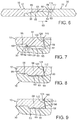
- FIG. 7 illustrates a tooth of the female ring of FIG. 6 as it reaches a tooth receiving groove of the male ring of FIG. 7 .
- FIG. 8 illustrates the tooth of FIG. 7 at a further position of advancement into the tooth receiving groove.
- FIG. 9 illustrates the tooth of FIG. 7 in the tooth receiving groove with a portion of the leading face of the tooth abutting the trailing face of the tooth receiving groove.
- FIG. 10 illustrates a more detailed view of the female ring of FIG. 6 .
- FIG. 11 illustrates a more detailed view of the male ring of FIG. 6 .
- FIG. 12 illustrates an enlarged view of the tooth of FIG. 10 .
- Any suitable durable material can be used for the pipes and pipe joint forming couplers disclosed herein, such as, for example, steel, with ASTM A36 carbon structural steel being one specific example.
- FIGS. 1 through 5 a first exemplary embodiment of pipe ram joint couplers is illustrated.
- An annular first coupler 10 shown in the form of a first annular ring 12 , which constitutes an outer or OD ring, is desirably circular in cross-section.
- a proximal end 14 (“proximal” means at the pipe end to which it is to be connected) desirably has converging weld surfaces for use in welding (e.g., butt welding) end 14 to the end of a pipe section to thereby attach ring 12 to the pipe section.
- FIG. 4 illustrates end 14 connected by welds 16 , 18 to a first end 20 of a first pipe 22 .
- An annular second coupler 30 shown in the form of a second annular ring 32 , which constitutes an inner or ID ring, is also desirably circular in cross section.
- a proximal end 34 desirably has converging weld surfaces for use in welding (e.g., butt welding) end 34 to the end of a pipe section to thereby attach ring 32 to the pipe section.
- FIG. 4 illustrates end 34 connected by welds 36 , 38 to a second end 40 of a second pipe 42 .
- these rings are pre-attached to pipe lengths, a female ring 12 being at one end of the pipe length and a male ring 32 at the other end, such as by welding, prior to delivery of the pipe lengths to an installation site. Lengths of pipes with these rings are then ready to be added to a string of one or more pipes as the pipe string is being driven through the ground.
- ring 32 will be at the trailing end of a string of pipe sections being driven through the ground and ring 12 will be at the leading end of the next pipe section to be joined in the pipe string.
- ring 12 desirably has at least three main annular sections, namely, an annular first trailing coupling end section 50 , a middle annular groove defining section 52 that defines a first annular groove 53 , and an annular front, or first leading end section 54 comprising an annular first tooth 58 .
- the illustrated leading end section 52 terminates in a first distal end 56 .
- the ring 32 desirably also has at least three main annular sections, namely, a second trailing or coupling end section 60 , a middle annular groove defining section 62 that defines a second annular groove 63 , and an annular front, or second leading end section 64 comprising an annular second tooth 66 .
- the second leading end section terminates in a second distal end 68 .
- the annular first coupler or ring 12 has a first longitudinal axis 70 coaxial with the longitudinal axis of the pipe to which the ring is coupled.
- the first coupler is mounted to ( FIG. 4 ) or formed in ( FIG. 5 ) a first end of a first pipe.
- an annular second coupler or ring 32 has a second longitudinal axis 72 coaxial with the longitudinal axis of the pipe to which the ring is coupled.
- the second coupler is mounted to ( FIG. 4 ) or formed in ( FIG. 5 ) a second end of a second pipe.
- the ring 12 comprises the first distal end 56 , an annular first outer wall 74 and an annular first inner wall 76 .
- the walls 74 , 76 are desirably circular in cross section. Desirably the diameter of inner wall 76 is the same diameter as the inner diameter of the pipe to which ring 12 is to be mounted and the diameter of the outer wall 74 is the same diameter as outer diameter of the pipe to which the ring is to be mounted.
- the first distal end 56 defines a first pipe receiving opening 78 that is desirably circular in cross section.
- the second coupler comprises the second distal end 68 , an annular second outer wall 80 and an annular second inner wall 82 .
- the walls 80 , 82 are desirably circular in cross section.
- the diameter of inner wall 82 is the same diameter as the inner diameter of the pipe to which ring 30 is to be mounted and the diameter of the outer wall 80 is the same diameter as outer diameter of the pipe to which the ring is to be mounted.
- the rings can have a thickness that is greater than the thickness of the adjoining pipes, such that, for example, the OD dimension of the rings is greater than the OD dimension of the connected pipes.
- the ID dimension of the rings matches the ID dimension of the pipes.
- the second distal end 68 and the second coupler are sized for insertion into the first pipe receiving opening 78 and into the first ring 12 to position the first tooth 58 of the first ring in the second groove 63 of the second ring and the second tooth 66 of the second ring 32 in the first groove 53 of the first ring to join the first and second rings and pipes carrying these rings together.
- the inner and outer diameters of coupler sections 50 and 64 are desirably the same and can be the same diameter as the diameter of the pipes to which the couplers are attached.
- the tooth 58 and the groove 53 are recessed into the inner wall 76 of coupler 10 with the tooth 58 having an outer tooth wall 59 that is nearer to the first longitudinal axis 70 than a base wall 55 at the base of the groove 53 .
- the tooth 66 and the groove 63 are recessed into the outer wall 80 of coupler 30 with the tooth 66 having an outer tooth wall 67 that is further from the second longitudinal axis 72 than a base wall 65 at the base of the groove 63 .
- the first inner wall 76 thus comprises an annular first groove 53 spaced from the first distal end 56 , and an annular first tooth 58 positioned nearer to the first distal end 56 than the distance from the first annular groove 53 to the distal end 56 .
- the first groove is defined by a first annular groove side wall 90 , the base wall 55 and a second annular groove side wall 92 .
- the side wall 92 leads the side wall 90 if ring 12 in the direction of motion if the ring 12 is moved in the drive direction indicated by arrow 93 in FIG. 1 .
- the drive direction 93 in FIGS. 1 and 2 corresponds to an exemplary direction that a pipe string is being driven into the ground.
- the first groove side wall 90 is spaced further from the first distal end 56 than the second groove side wall 92 .
- the illustrated first groove side wall 90 has an annular first face or first surface 94 that is undercut and angled toward the distal end 56 and that faces the drive direction of motion of ring 12 . That is, the first groove side wall 94 and its associated surface 94 is angled toward the first distal end at a first acute angle A relative to a plane 96 that is perpendicular to the first longitudinal axis 70 and moving away in a direction from the first groove base wall 55 .
- the second groove side wall 90 has an annular second face or associated surface 98 that is angled toward the distal end 56 moving away from the base wall 55 .
- the second groove side wall and surface 98 is angled toward the first distal end at a second acute angle B relative to a plane 100 that is perpendicular to the first longitudinal axis 70 and moving in a direction away from the first groove base wall 55 .
- the illustrated the first tooth 58 is bounded by first and second annular tooth side walls respectively at opposite ends of the first tooth outer wall 59 .
- the first tooth first side wall of tooth 58 is also the second groove side wall 92 is positioned further from the first distal end 56 than the second tooth side wall 110 .
- At least a portion 112 of the second tooth side wall 110 comprises an annular first tooth side wall groove wall engaging surface. The surface 112 is angled toward the distal end 56 of the first tooth 58 at a third acute angle C relative to a plane 114 perpendicular to the first longitudinal axis 70 and moving in a direction away from the first outer wall 74 .
- the second outer wall 80 thus comprises an annular second groove 63 spaced from the second distal end 68 , and an annular second tooth 66 positioned nearer to the second distal end 68 than the distance from the second annular groove 63 to the distal end 68 .
- the second tooth 66 desirably has a longer length (the length of section 64 , the length dimension being in the direction of the longitudinal axis 72 ) than the length of the first tooth 58 (the length of section 54 , the length dimension being in the direction of the longitudinal axis 70 ).
- the second groove is defined by a third annular groove side wall 120 , the base wall 65 and a fourth annular groove side wall 122 .
- the side wall 122 leads the side wall 120 if ring the 32 is moved in the drive direction indicated by arrow 93 .
- the third groove side wall 120 is spaced nearer to the second distal end 68 than the fourth groove side wall 122 .
- the illustrated fourth groove side wall 122 has an annular fourth face or associated fourth surface 124 that is undercut and angled toward the distal end 68 and that faces away from drive direction 93 . That is, the fourth groove side wall 122 and surface 124 is desirably angled toward the second distal end 68 at a fourth acute angle D relative to a plane 126 that is perpendicular to the second longitudinal axis 72 moving away from the second groove base wall 65 .
- the third groove side wall 120 has an annular third face or associated surface 128 that is angled toward the distal end 68 moving away from the base wall 65 . That is, the third groove side wall 120 and surface 128 are angled toward the second distal end 68 at a third acute angle E relative to a plane 130 that is perpendicular to the second longitudinal axis 72 moving away from the second groove base wall 65 .
- the illustrated the second tooth 66 is bounded by first and second annular tooth side walls respectively at opposite ends of a second tooth outer wall 69 .
- the first tooth side wall of tooth 66 is also the third groove side wall 120 (angled at angel E as explained above) in this embodiment.
- the first tooth side wall of tooth 66 is positioned further from the first distal end 68 than a second tooth side wall 140 .
- At least a portion 142 of the second tooth side wall 140 desirably comprises an annular a second tooth side wall groove wall engaging surface.
- the surface 142 in this exemplary embodiment is angled toward the distal end 68 of the second tooth 66 at an acute angle F relative to a plane 144 that is perpendicular to the second longitudinal axis 72 in a direction moving away from the second inner wall 82 .
- the first tooth 58 is sized for positioning in the second groove 63 with at least a portion of the first side wall groove wall engaging surface 112 abutting the fourth groove side wall 122 and surface 124 .
- the second tooth 66 is sized for positioning in the first groove 53 with at least a portion of the second tooth side wall groove wall engaging surface 142 abutting the first side wall 90 and surface 94 .
- the length of tooth base wall 59 of the first tooth can be the same as the length of the second groove base wall 65 . However, the first tooth base wall 59 length can be longer than the second groove base wall 65 , as explained below in connection with FIGS.
- angles B and E can be the same (such as twenty-five to thirty-five degrees, with thirty degrees being one example) and greater than the angles C and D.
- angles A, F and C, D can be the same (such as from four to fifteen degrees with ten degrees being one specific example in the FIG. 1 embodiment). However, these angles A, F; C, D; and B, E; can be different from one another. For example, as explained below in connection with FIGS. 7-9 , angle C can be less than angle D, such as ten percent less. This reduces the bearing surface of the first side wall groove engaging surface 112 against the fourth groove side wall 122 .
- the sum of: (a) the thicknesses of the first ring 12 from the first tooth outer wall 59 to the first outer wall 74 in the radial direction away from longitudinal axis 70 ; and (b) the thickness of the second ring 32 from the base wall 65 of the second groove 63 to the second inner wall 82 of the second ring, can be equal to the thickness of the T between the inner and outer walls of the rings 12 , 32 and the thickness of the pipes to which the rings are attached.
- the thickness of the rings can be greater than the thickness of the pipes.
- the thickness of the first ring 12 along the length of the first groove 53 can be, for example, about ten to thirty percent of the thickness T.
- T can be 1.25 inches.
- the sum of: (a) the thicknesses of the second ring 32 from the second tooth outer wall 69 to the second inner wall 82 in the radial direction away from longitudinal axis 72 ; and (b) the thickness of the first 12 from the base wall 55 of the first groove 53 to the first outer wall 74 of the first ring, can be equal to the thickness T between the inner and outer walls of the rings 12 , 32 and the thickness of the pipes to which the rings are attached.
- the thickness of the second ring 12 along the length of the second groove 63 can be, for example, about forty to sixty percent of the thickness T.
- first groove base wall 55 desirably diverges in this embodiment from the first longitudinal axis 70 in a direction from the first groove side wall 90 toward the second groove side wall 92 .
- the entire length of the base wall surface 65 can diverge in this manner along its length.
- the radius of at least a first portion of the first groove 53 from the first longitudinal axis 70 increases at a first rate moving from the first groove side wall toward the second groove side wall along the first portion of the base wall 55 of the first groove 53 . This is indicated by the slope of acute angle G in FIG. 1 .
- At least a second portion of the surface of second tooth outer wall 69 desirably diverges in this embodiment from the second longitudinal axis 70 in a direction from the second tooth side wall 140 to the second tooth side wall 120 .
- the entire length of the second outer tooth wall surface 69 can diverge in this manner along its length.
- the radius of at least a first portion of the second tooth outer wall from the second longitudinal axis 72 increases at a second rate moving from the second tooth side wall 140 toward the second tooth side wall 120 along a portion of the second tooth outer wall 69 .
- This is indicated by the slope of acute angle H in FIG. 2 .
- the surface 69 in FIG. 2 can thus comprise an annular tapering surface.
- the thickness of tooth 66 can progressively become thinner moving toward the distal end 68 .
- this tapering can be continuous until a chamfered portion 162 is reached.
- the angle H can be greater than the angle G as this is understood to reduce the force required to ram the coupling rings together. That is, the second rate can be greater than the first rate.
- the radius of at least a second portion of the second tooth from the second longitudinal axis increases at a second rate that is greater than the first rate moving from the fourth tooth side wall surface 142 toward the third tooth side wall surface 128 along the second portion of the second tooth.
- the angle H can be from one-half to three degrees, with two degrees being a specific example and the angle G can be from one-half to two and one-half degrees, with one degree being a specific example.
- the first leading face or surface 94 is located at the forward or leading end of section 50 of ring 12 , adjacent to and at the transition to middle section 52 .
- leading face refers to a face that is facing toward the drive direction 93
- a “trailing face” refers to a face that is facing away from the drive direction 93 .
- the first leading face 94 is angled to make contact with a trailing face or surface 142 of the second ring 32 when the rings are rammed together (such as shown in FIGS. 4 and 5 ) to join the pipe sections to which the rings are attached or in which the coupling elements of the rings are formed.
- first leading face 94 is annular and is angled at an acute angle A relative to a transverse plane 96 perpendicular to the longitudinal axis 70 .
- the surface 94 is oriented to slant in a direction opposite to the drive direction 93 moving from the inner wall surface 76 toward the outer wall surface 74 .
- ring 32 comprises a first trailing face 122 that is annular and is angled at the acute angle D relative to a transverse plane 126 perpendicular to the second longitudinal axis 72 and also perpendicular to the drive direction 93 .
- the surface 122 of ring section 32 is oriented to slant in a direction opposite to the drive direction 93 moving from the inner wall 82 toward the outer wall 80 of ring section 32 .
- the engaging faces 112 , 122 , and the respective acute angles of these surfaces result in the joint becoming tighter as ring 12 is driving onto ring 32 and these rings are driven together by impacting the tail end of the pipe of a pipe string containing the joint comprising ring sections 12 and 32 .
- the middle section 52 of ring section 12 defines the annular groove 53 .
- the middle section 52 is thinner than rear end section 50 , such as being about one-third of the thickness of the rear end section 52 .
- the inner surface of the groove 53 that is the groove base wall 55 , can taper moving toward leading or front ring section 54 and, in this example, the pipe wall becomes thinner moving in this direction in the exemplary embodiment.
- the distal end portion of ring 12 namely the inner wall of the front end section 54 , comprises the annular first tooth portion 58 .
- the tooth portion 58 projects inwardly away from the outer wall 74 of ring section 12 . Tooth 58 is in effect cantilevered by middle section or portion 52 from the rear end section 50 of the ring 12 .
- the tooth 58 comprises the trailing face 98 and leading face 112 .
- the distal interior peripheral edge 160 of the tooth 58 , and/or the distal exterior peripheral edge 162 of tooth 66 can be beveled or chamfered to facilitate insertion of the ring 32 into the opening 78 of the ring 12 as pipes with the mounted and/or formed rings 12 , 32 , are brought together.
- the tooth 58 is driven deeper into the groove 63 with the driving forces being transmitted via the engaged surfaces 112 , 124 to a leading section of pipe of a pipe string to thereby enhance pipe ramming and driving.
- the tooth 58 is driven into further engagement within the groove 63 until a maximum engaged position is reached.
- the corresponding lagging face 128 of groove 63 desirably abuts the lagging face 98 of tooth 58 when the tooth 58 is positioned in the groove 63 .
- the tooth 66 is driven into the groove 53 with lagging face 142 of the tooth 66 engaging the lagging face 96 of the groove 53 .
- FIG. 3 illustrates ring section 12 and ring section 32 as these two ring sections are being driven together by applying an impact force in the drive direction to the end of the pipe containing ring section 12 .
- the outer wall 59 of tooth 58 engages and slides along the outer wall 69 of the tooth 66 with the tooth 58 moving toward the second groove 63 .
- the surface 69 in embodiments where angle H is greater than angle G is spaced from the surface 55 due to the difference between the angle G and the angle H, which assists in reducing the required ramming force.
- a lubricant such as a silicon sealant, can be placed between the sliding surfaces to facilitate sliding of the engaged surfaces.
- a female ring coupler 10 is brought toward the male ring coupler 30 projecting from the ground.
- the pipe with the female ring coupler is angled such that the top or bottom portion of the female coupler first engages the corresponding portion of the exposed male coupler.
- the pipe with the female coupler is then tilted to align the couplers and the female coupler is rammed into the male coupler.
- a temporary push ring is typically placed onto the male coupler at the opposite end of the pipe with the female coupler for use during the connection and ramming operation to protect the male coupler.
- FIGS. 4 and 5 illustrate the ring sections 12 and 32 in an interconnected position with tooth 58 positioned within groove 63 and tooth 66 positioned within groove 53 .
- the tooth 58 is driven deeper into the recess or groove 63 leading to a tighter fit and a more efficiently functioning joint as energy is more effectively transferred through the joint toward the leading end of the string of pipes being driven into the soil.
- a first gap or recess is provided by the chamfer 160 at the base of the groove 53 adjacent to the abutting surfaces 94 , 142 and a second recess or gap 32 is provided at the base of the groove 63 adjacent to the abutting surfaces 112 , 122 .
- FIG. 5 illustrates an alternative embodiment in which the structural features of ring components 12 , 32 as is described in connection with FIGS. 1 and 2 (except for the weld coupling portions) are machined into the ends of respective pipe sections rather than being provided in rings that are attached to pipe lengths.
- the structural features of coupler 10 with the exception of the welding features at the end 14 of the ring, are machined into an end of the first pipe 22 .
- the structural features of coupler 30 with the exception of the welding features at the end 34 of ring 32 , are machined into an end of a second pipe 42 .
- the pipe sections 22 , 42 are shown rammed together to form the joint between the couplers 10 , 30 .
- FIGS. 6-12 elements in common with the elements of the embodiment of FIGS. 1-5 have been given the same numbers, to which the above description applies, except as differences are noted in the description below. These common elements will not be discussed further except as appropriate to describe the differences between these embodiments. It is expected that the embodiment of FIGS. 6-12 will require a lesser ramming force to ram the couplers together than the ramming force required to ram the couplers of the embodiment of FIGS. 1-5 together.
- the elements of the couplers of FIGS. 6-12 can be provided in rings mounted to the ends of pipes or formed into pipe ends as explained above.
- At least the majority of the first groove base wall 55 is concave and at least a majority of the second tooth outer wall 69 is convex. More desirably, the entire length of the base wall 55 can be concave and the entire length of the second tooth outer wall 69 can be convex.
- the surfaces 55 and 69 are shown with respective radii R 1 and R 2 . Although they can be different, R 1 and R 2 can be the same, such as between eighteen and twenty-five inches, with twenty-one inches being one exemplary radii dimension.
- the concave surface 69 facilitates the sliding of the tooth surface 59 along this surface and is expected to reduce the ramming force required to urge the tooth 58 into the second groove 63 .
- the concave surface 55 facilitates the sliding of surface 69 into the groove 53 .
- angles A and F can be less than in the FIGS. 1 and 2 embodiment, such as from four to eight degrees, with six degrees being a specific example.
- the tooth 58 has been modified. More specifically, although not required, the first side wall groove engaging surface 112 has been expanded to cover the entire tooth wall 110 of the tooth. In addition, the chamfer 160 has been eliminated and replaced with a pointed tip at the first distal end 56 , which is typically polished to provide a small radius of curvature to the tip, such as less than a 0.2 inch radius.
- the angle C in the FIGS. 6-12 embodiment can be made smaller than the angle D, such as five to twenty percent smaller, with a ten percent reduction being a specific example.
- the angle C can be nine degrees and the angle D can be ten degrees.
- the length dimension of tooth outer wall 59 in the drive direction 93 can be made longer than the length dimension of the base wall 65 of the groove 63 .
- FIGS. 7-9 the progress of tooth 58 into the groove 63 is shown.
- the tooth 58 has advanced to the location where a tooth corner 190 between surfaces 59 and 98 is at the lagging edge of the groove 63 at the top of groove wall 120 .
- a gap exists between leading tooth surface 112 and the groove side wall surface 124 .
- the tooth 158 has entered the groove 63 .
- the tooth 58 is fully positioned in the groove 63 .
- the angle C is less than the angle D, as shown in FIG.
- the distal end 56 comprises at least a portion of the first groove side wall engaging surface that engages wall surface 124 , but a gap 194 exists between the upper portion of surface 112 and the groove side wall surface 124 .
- a gap 196 exists between the surfaces 59 and 65 .
- these surfaces do not bear against one another as the couplers are driven together, which also is expected to reduce the ramming force required to drive the couplers together and to reduce or eliminate “bounce back”; the recoil energy of the pipe that otherwise would tend to force the pipe joint apart after ramming impact as the pipe string is advanced through the soil and also during joint formation.
- FIG. 6 illustrates the couplers 10 , 30 of FIGS. 10 and 11 after they have been driven together.
Landscapes
- Engineering & Computer Science (AREA)
- General Engineering & Computer Science (AREA)
- Mechanical Engineering (AREA)
- Life Sciences & Earth Sciences (AREA)
- Geology (AREA)
- Mining & Mineral Resources (AREA)
- Physics & Mathematics (AREA)
- Fluid Mechanics (AREA)
- Environmental & Geological Engineering (AREA)
- General Life Sciences & Earth Sciences (AREA)
- Geochemistry & Mineralogy (AREA)
- Mutual Connection Of Rods And Tubes (AREA)
Abstract
Description
Claims (30)
Priority Applications (1)
| Application Number | Priority Date | Filing Date | Title |
|---|---|---|---|
| US15/589,608 US10619778B2 (en) | 2016-05-06 | 2017-05-08 | Pipe ram joint |
Applications Claiming Priority (2)
| Application Number | Priority Date | Filing Date | Title |
|---|---|---|---|
| US201662333072P | 2016-05-06 | 2016-05-06 | |
| US15/589,608 US10619778B2 (en) | 2016-05-06 | 2017-05-08 | Pipe ram joint |
Publications (2)
| Publication Number | Publication Date |
|---|---|
| US20170321834A1 US20170321834A1 (en) | 2017-11-09 |
| US10619778B2 true US10619778B2 (en) | 2020-04-14 |
Family
ID=60243311
Family Applications (1)
| Application Number | Title | Priority Date | Filing Date |
|---|---|---|---|
| US15/589,608 Active 2038-11-21 US10619778B2 (en) | 2016-05-06 | 2017-05-08 | Pipe ram joint |
Country Status (1)
| Country | Link |
|---|---|
| US (1) | US10619778B2 (en) |
Cited By (2)
| Publication number | Priority date | Publication date | Assignee | Title |
|---|---|---|---|---|
| US20230193699A1 (en) * | 2019-04-22 | 2023-06-22 | Oil States Industries, Inc. | Expandable connection for expandable tubulars |
| US20250283566A1 (en) * | 2024-03-07 | 2025-09-11 | Trinity Products, Llc | Fittings for joining lengths of pipe and pipe assembly formed using same |
Families Citing this family (3)
| Publication number | Priority date | Publication date | Assignee | Title |
|---|---|---|---|---|
| US10823320B1 (en) * | 2017-02-10 | 2020-11-03 | Northwest Pipe Company | Pipe joint |
| KR101920248B1 (en) * | 2018-06-21 | 2019-02-08 | 박수복 | Fuel Saving Device for Vehicle and Manufacturing Method Thereof |
| AU2023377704A1 (en) * | 2022-11-07 | 2025-05-08 | NWPX Infrastructure, Inc. | Coupling system for articulating pipe joint |
Citations (36)
| Publication number | Priority date | Publication date | Assignee | Title |
|---|---|---|---|---|
| US672180A (en) * | 1900-07-10 | 1901-04-16 | Robert W Read | Hose-coupling. |
| US786929A (en) | 1904-07-20 | 1905-04-11 | William T Waite | Pipe or hose coupling. |
| US2257335A (en) | 1940-04-05 | 1941-09-30 | Hughes Tool Co | Tool joint welding |
| US2893759A (en) | 1957-05-06 | 1959-07-07 | Smith Corp A O | Conically tapered screw-type casing joint with metal-to-metal seal |
| US3074292A (en) | 1960-09-14 | 1963-01-22 | Anthony P Polmon | Knob and self-locking insert |
| US3096105A (en) | 1960-09-09 | 1963-07-02 | Dresser Ind | Split arrestor having circumferentially extending grain structure for welded pipelines having longitudinally extending grain structure |
| US3114566A (en) | 1961-04-21 | 1963-12-17 | Kobe Inc | Shrink fit tubing joint |
| US3640552A (en) * | 1969-08-13 | 1972-02-08 | Amp Inc | Vacuum or pressure coupling devices |
| US3751077A (en) | 1972-02-28 | 1973-08-07 | Imp Eastman Corp | Welded sleeve fitting |
| US3751792A (en) | 1971-06-23 | 1973-08-14 | Gazer Corp | Method of forming a welded joint construction |
| US3774296A (en) | 1972-09-29 | 1973-11-27 | Hahn & Clay | Method of manufacturing a pressure vessel assembly |
| US3784235A (en) | 1971-10-08 | 1974-01-08 | Us Navy | Tubular adhesive joint with snap lock |
| USRE29376E (en) | 1972-02-28 | 1977-08-30 | Imperial-Eastman Corporation | Welded sleeve fitting |
| US4091630A (en) | 1977-05-03 | 1978-05-30 | Kubota, Ltd. | Intermediate sleeve for installing pipeline by propelling pipes underground |
| US4124232A (en) | 1977-05-04 | 1978-11-07 | Vetco, Inc. | Rigid pipe connector with lock elements and method of making the same |
| US4214358A (en) | 1977-03-25 | 1980-07-29 | Commissariat A L'energie Atomique | Method of assembly of two metallic parts |
| US4275907A (en) | 1976-10-05 | 1981-06-30 | Huntal Manufacturing Company Incorporated | Quick connectable coupling |
| US4298221A (en) | 1977-01-26 | 1981-11-03 | Hunting Oilfield Services (U.K.) Limited | Pipe connectors |
| US4341481A (en) | 1980-09-22 | 1982-07-27 | Sanford Research Company | Writing instrument with barrel and ferrule assembly |
| US4525001A (en) | 1982-01-18 | 1985-06-25 | Hunting Oilfield Services (Uk) Limited | Pipe connector with interengagable tubular pin and tubular box members |
| US4629221A (en) | 1983-04-05 | 1986-12-16 | Hunting Oilfield Services (Uk) Ltd. | Pipe connectors |
| US4687368A (en) | 1985-04-04 | 1987-08-18 | Santrade Limited | Thread structure for percussion rock drilling |
| US4728236A (en) | 1985-07-19 | 1988-03-01 | Trw United Carr Gmbh | Fastening device for use on threaded bolts or studs |
| US4779902A (en) | 1987-07-06 | 1988-10-25 | Mid-Continent Pipe & Supply Co., Inc. | Plastic pipe with integral end connection |
| US4790573A (en) | 1986-07-07 | 1988-12-13 | Tubos E Conexoes Tigre S/A | Sealing system between a metal insert and plastic coupling, and resulting product |
| US4817997A (en) | 1987-06-25 | 1989-04-04 | Ingram Thomas L | Hose coupling |
| US4919461A (en) | 1986-07-25 | 1990-04-24 | Lucas Industries Public Limited Company | Pressure cylinder pipe coupling |
| US4958959A (en) | 1981-07-10 | 1990-09-25 | Duratron Systems Limited | Method of relining sewers and water lines without excavation |
| US5015014A (en) | 1989-06-19 | 1991-05-14 | Aardvark Corporation, Inc. | Plastic pipe section |
| US5104263A (en) | 1988-10-05 | 1992-04-14 | Sekisui Kagaku Kogyo Kabushiki Kaisha | Underground pipe for a thrust boring method and a connecting construction of the underground pipe for the same |
| US5360242A (en) | 1992-10-07 | 1994-11-01 | Argent Michael F | Pipe connecting assembly and method for joining two lengths of steel pipe by a press-fit connection |
| WO1996013681A1 (en) * | 1994-10-31 | 1996-05-09 | Argent Michael E | Pipe connecting assembly and method for joining two lengths of pipe by a press-fit connection |
| US20060170213A1 (en) * | 2005-01-14 | 2006-08-03 | Mittler David A | Methods and devices for horizontal directional drilling and other procedures |
| US7648176B2 (en) | 2000-02-23 | 2010-01-19 | Plexus Ocean Systems, Ltd. | Pipe joint |
| US20130161027A1 (en) * | 2011-12-22 | 2013-06-27 | Halliburton Energy Services, Inc. | Unequal Load Collet and Method of Use |
| DE202014003776U1 (en) * | 2014-05-07 | 2014-05-20 | Karl Schangen Kg Kunststoff-Rohrsysteme | Plastic pipe |
-
2017
- 2017-05-08 US US15/589,608 patent/US10619778B2/en active Active
Patent Citations (37)
| Publication number | Priority date | Publication date | Assignee | Title |
|---|---|---|---|---|
| US672180A (en) * | 1900-07-10 | 1901-04-16 | Robert W Read | Hose-coupling. |
| US786929A (en) | 1904-07-20 | 1905-04-11 | William T Waite | Pipe or hose coupling. |
| US2257335A (en) | 1940-04-05 | 1941-09-30 | Hughes Tool Co | Tool joint welding |
| US2893759A (en) | 1957-05-06 | 1959-07-07 | Smith Corp A O | Conically tapered screw-type casing joint with metal-to-metal seal |
| US3096105A (en) | 1960-09-09 | 1963-07-02 | Dresser Ind | Split arrestor having circumferentially extending grain structure for welded pipelines having longitudinally extending grain structure |
| US3074292A (en) | 1960-09-14 | 1963-01-22 | Anthony P Polmon | Knob and self-locking insert |
| US3114566A (en) | 1961-04-21 | 1963-12-17 | Kobe Inc | Shrink fit tubing joint |
| US3640552A (en) * | 1969-08-13 | 1972-02-08 | Amp Inc | Vacuum or pressure coupling devices |
| US3751792A (en) | 1971-06-23 | 1973-08-14 | Gazer Corp | Method of forming a welded joint construction |
| US3784235A (en) | 1971-10-08 | 1974-01-08 | Us Navy | Tubular adhesive joint with snap lock |
| US3751077A (en) | 1972-02-28 | 1973-08-07 | Imp Eastman Corp | Welded sleeve fitting |
| USRE29376E (en) | 1972-02-28 | 1977-08-30 | Imperial-Eastman Corporation | Welded sleeve fitting |
| US3774296A (en) | 1972-09-29 | 1973-11-27 | Hahn & Clay | Method of manufacturing a pressure vessel assembly |
| US4275907A (en) | 1976-10-05 | 1981-06-30 | Huntal Manufacturing Company Incorporated | Quick connectable coupling |
| US4298221A (en) | 1977-01-26 | 1981-11-03 | Hunting Oilfield Services (U.K.) Limited | Pipe connectors |
| US4214358A (en) | 1977-03-25 | 1980-07-29 | Commissariat A L'energie Atomique | Method of assembly of two metallic parts |
| US4091630A (en) | 1977-05-03 | 1978-05-30 | Kubota, Ltd. | Intermediate sleeve for installing pipeline by propelling pipes underground |
| US4124232A (en) | 1977-05-04 | 1978-11-07 | Vetco, Inc. | Rigid pipe connector with lock elements and method of making the same |
| US4341481A (en) | 1980-09-22 | 1982-07-27 | Sanford Research Company | Writing instrument with barrel and ferrule assembly |
| US4958959A (en) | 1981-07-10 | 1990-09-25 | Duratron Systems Limited | Method of relining sewers and water lines without excavation |
| US4525001A (en) | 1982-01-18 | 1985-06-25 | Hunting Oilfield Services (Uk) Limited | Pipe connector with interengagable tubular pin and tubular box members |
| US4629221A (en) | 1983-04-05 | 1986-12-16 | Hunting Oilfield Services (Uk) Ltd. | Pipe connectors |
| US4687368A (en) | 1985-04-04 | 1987-08-18 | Santrade Limited | Thread structure for percussion rock drilling |
| US4728236A (en) | 1985-07-19 | 1988-03-01 | Trw United Carr Gmbh | Fastening device for use on threaded bolts or studs |
| US4790573A (en) | 1986-07-07 | 1988-12-13 | Tubos E Conexoes Tigre S/A | Sealing system between a metal insert and plastic coupling, and resulting product |
| US4919461A (en) | 1986-07-25 | 1990-04-24 | Lucas Industries Public Limited Company | Pressure cylinder pipe coupling |
| US4817997A (en) | 1987-06-25 | 1989-04-04 | Ingram Thomas L | Hose coupling |
| US4779902A (en) | 1987-07-06 | 1988-10-25 | Mid-Continent Pipe & Supply Co., Inc. | Plastic pipe with integral end connection |
| US5104263A (en) | 1988-10-05 | 1992-04-14 | Sekisui Kagaku Kogyo Kabushiki Kaisha | Underground pipe for a thrust boring method and a connecting construction of the underground pipe for the same |
| US5015014A (en) | 1989-06-19 | 1991-05-14 | Aardvark Corporation, Inc. | Plastic pipe section |
| US5360242A (en) | 1992-10-07 | 1994-11-01 | Argent Michael F | Pipe connecting assembly and method for joining two lengths of steel pipe by a press-fit connection |
| US5921591A (en) | 1992-10-07 | 1999-07-13 | Argent; Michael E. | Pipe connecting assembly and method for joining two lengths of pipe by a press-fit connection |
| WO1996013681A1 (en) * | 1994-10-31 | 1996-05-09 | Argent Michael E | Pipe connecting assembly and method for joining two lengths of pipe by a press-fit connection |
| US7648176B2 (en) | 2000-02-23 | 2010-01-19 | Plexus Ocean Systems, Ltd. | Pipe joint |
| US20060170213A1 (en) * | 2005-01-14 | 2006-08-03 | Mittler David A | Methods and devices for horizontal directional drilling and other procedures |
| US20130161027A1 (en) * | 2011-12-22 | 2013-06-27 | Halliburton Energy Services, Inc. | Unequal Load Collet and Method of Use |
| DE202014003776U1 (en) * | 2014-05-07 | 2014-05-20 | Karl Schangen Kg Kunststoff-Rohrsysteme | Plastic pipe |
Non-Patent Citations (6)
| Title |
|---|
| Aardvark Corporation advertisement for "Barbvark quick connect pipe joints"; pre-1994; one page. |
| Case study; "Almost instant sewer replacement at Blisworth"; Russell Smith; pre-1994; 2 pages. |
| Chow; "Snap-fit design concepts"; Modern Plastics; Aug. 1977; pp. 56-59. |
| McIntyre; "Designing for snap fits, part 2"; Plastics Design Forum; Jul./Aug. 1984; 5 pages. |
| McIntyre; "Designing for snap fits, part 3"; Plastics Design Forum; Sep./Oct. 1984; 4 pages. |
| Wuebken, et al.; "Designing for snap fits, part 1"; Plastics Design Forum; May/Jun. 1984; 3 pages. |
Cited By (3)
| Publication number | Priority date | Publication date | Assignee | Title |
|---|---|---|---|---|
| US20230193699A1 (en) * | 2019-04-22 | 2023-06-22 | Oil States Industries, Inc. | Expandable connection for expandable tubulars |
| US20230193700A1 (en) * | 2019-04-22 | 2023-06-22 | Oil States Industries, Inc. | Expandable connection for expandable tubulars |
| US20250283566A1 (en) * | 2024-03-07 | 2025-09-11 | Trinity Products, Llc | Fittings for joining lengths of pipe and pipe assembly formed using same |
Also Published As
| Publication number | Publication date |
|---|---|
| US20170321834A1 (en) | 2017-11-09 |
Similar Documents
| Publication | Publication Date | Title |
|---|---|---|
| US10619778B2 (en) | Pipe ram joint | |
| US6176523B1 (en) | Joint for variable wall thickness conduit | |
| US5547230A (en) | Joint for variable wall thickness conduit | |
| EP1232321B1 (en) | A thread joint, a male portion and a female portion | |
| US10006255B2 (en) | Tapered spline connection for drill pipe, casing, and tubing | |
| US20160039042A1 (en) | Method for Friction Welding Subsea Flowline Connectors | |
| US3720069A (en) | Pipeline laying operation with explosive joining of pipe sections | |
| US20130180728A1 (en) | Welded Downhole Components and Method of Forming Same | |
| GB2059533A (en) | Method of joining pipes to pipe sleeves | |
| US8348542B2 (en) | Connection system for tubular members | |
| JP2000054795A (en) | Segment | |
| EP3389919B1 (en) | Method for connection and tubular connection assembly for improved fatigue performance of metallic risers | |
| US10704724B1 (en) | Fittings for joining lengths of pipe by a press-fit connection and pipe assembly formed using same | |
| GB2373750A (en) | Welding pipe-in-pipe pipelines | |
| USRE50368E1 (en) | Pipe joint | |
| US20210324685A1 (en) | Interlocking tubular with sectioned parts and related method | |
| JP5140114B2 (en) | Joining method of ready-made piles, Joined hardware of ready-made piles | |
| US4547096A (en) | Alignment of tubular piles for joinder | |
| CN115263371B (en) | Rectangular jacking pipe capable of communicating pipe joint assembly and construction method | |
| JP2022114464A (en) | Ground reinforcement steel pipe | |
| JP4318696B2 (en) | Saya tube propulsion method | |
| JP2002276284A (en) | Sleeve jacking method and pipe joint structure used for it | |
| US20180023739A1 (en) | Apparatus and method for coupling | |
| US20240084649A1 (en) | Auger boring using a pipe seal assembly to join together casing pipe sections | |
| JP5899620B2 (en) | Excavation tool and manufacturing method thereof |
Legal Events
| Date | Code | Title | Description |
|---|---|---|---|
| STPP | Information on status: patent application and granting procedure in general |
Free format text: DOCKETED NEW CASE - READY FOR EXAMINATION |
|
| AS | Assignment |
Owner name: NORTHWEST PIPE COMPANY, WASHINGTON Free format text: ASSIGNMENT OF ASSIGNORS INTEREST;ASSIGNORS:KEIL, BRENT;GOBLER, FREDERICK;SIGNING DATES FROM 20170919 TO 20170922;REEL/FRAME:043852/0413 |
|
| AS | Assignment |
Owner name: WELLS FARGO BANK, NATIONAL ASSOCIATION, MINNESOTA Free format text: SECURITY INTEREST;ASSIGNORS:NORTHWEST PIPE COMPANY;AMERON WATER TRANSMISSION GROUP, LLC;PERMALOK CORPORATION;REEL/FRAME:047321/0961 Effective date: 20181025 |
|
| STPP | Information on status: patent application and granting procedure in general |
Free format text: NOTICE OF ALLOWANCE MAILED -- APPLICATION RECEIVED IN OFFICE OF PUBLICATIONS |
|
| STCF | Information on status: patent grant |
Free format text: PATENTED CASE |
|
| AS | Assignment |
Owner name: NORTHWEST PIPE COMPANY, WASHINGTON Free format text: RELEASE BY SECURED PARTY;ASSIGNOR:WELLS FARGO BANK, NATIONAL ASSOCIATION;REEL/FRAME:056747/0155 Effective date: 20210702 Owner name: PERMALOK CORPORATION, WASHINGTON Free format text: RELEASE BY SECURED PARTY;ASSIGNOR:WELLS FARGO BANK, NATIONAL ASSOCIATION;REEL/FRAME:056747/0155 Effective date: 20210702 Owner name: NWPC, LLC, WASHINGTON Free format text: RELEASE BY SECURED PARTY;ASSIGNOR:WELLS FARGO BANK, NATIONAL ASSOCIATION;REEL/FRAME:056747/0155 Effective date: 20210702 |
|
| AS | Assignment |
Owner name: WELLS FARGO BANK, NATIONAL ASSOCIATION, OREGON Free format text: SECURITY INTEREST;ASSIGNORS:NORTHWEST PIPE COMPANY;NWPC, LLC;REEL/FRAME:056749/0457 Effective date: 20210630 |
|
| MAFP | Maintenance fee payment |
Free format text: PAYMENT OF MAINTENANCE FEE, 4TH YEAR, LARGE ENTITY (ORIGINAL EVENT CODE: M1551); ENTITY STATUS OF PATENT OWNER: LARGE ENTITY Year of fee payment: 4 |
|
| AS | Assignment |
Owner name: NWPX INFRASTRUCTURE, INC., WASHINGTON Free format text: CHANGE OF NAME;ASSIGNOR:NORTHWEST PIPE COMPANY;REEL/FRAME:072039/0529 Effective date: 20250612 |
|
| AS | Assignment |
Owner name: WELLS FARGO BANK, NATIONAL ASSOCIATION, WASHINGTON Free format text: SECURITY INTEREST;ASSIGNOR:NWPX INFRASTRUCTURE, INC. (F/K/A NORTHWEST PIPE COMPANY);REEL/FRAME:072288/0917 Effective date: 20250916 |