US10617236B2 - Bagging station with shopping bag holder - Google Patents
Bagging station with shopping bag holder Download PDFInfo
- Publication number
- US10617236B2 US10617236B2 US16/390,295 US201916390295A US10617236B2 US 10617236 B2 US10617236 B2 US 10617236B2 US 201916390295 A US201916390295 A US 201916390295A US 10617236 B2 US10617236 B2 US 10617236B2
- Authority
- US
- United States
- Prior art keywords
- sliding door
- track slot
- bag
- coupled
- bagging station
- Prior art date
- Legal status (The legal status is an assumption and is not a legal conclusion. Google has not performed a legal analysis and makes no representation as to the accuracy of the status listed.)
- Active
Links
Images


Classifications
-
- A—HUMAN NECESSITIES
- A47—FURNITURE; DOMESTIC ARTICLES OR APPLIANCES; COFFEE MILLS; SPICE MILLS; SUCTION CLEANERS IN GENERAL
- A47F—SPECIAL FURNITURE, FITTINGS, OR ACCESSORIES FOR SHOPS, STOREHOUSES, BARS, RESTAURANTS OR THE LIKE; PAYING COUNTERS
- A47F9/00—Shop, bar, bank or like counters
- A47F9/02—Paying counters
- A47F9/04—Check-out counters, e.g. for self-service stores
- A47F9/042—Shopping bags or carton-dispensing systems therefor
-
- A—HUMAN NECESSITIES
- A47—FURNITURE; DOMESTIC ARTICLES OR APPLIANCES; COFFEE MILLS; SPICE MILLS; SUCTION CLEANERS IN GENERAL
- A47B—TABLES; DESKS; OFFICE FURNITURE; CABINETS; DRAWERS; GENERAL DETAILS OF FURNITURE
- A47B49/00—Revolving cabinets or racks; Cabinets or racks with revolving parts
-
- A—HUMAN NECESSITIES
- A47—FURNITURE; DOMESTIC ARTICLES OR APPLIANCES; COFFEE MILLS; SPICE MILLS; SUCTION CLEANERS IN GENERAL
- A47F—SPECIAL FURNITURE, FITTINGS, OR ACCESSORIES FOR SHOPS, STOREHOUSES, BARS, RESTAURANTS OR THE LIKE; PAYING COUNTERS
- A47F13/00—Shop or like accessories
- A47F13/08—Hand implements, e.g. grocers' scoops, ladles, paper-bag holders
- A47F13/085—Shopping-bag holders
-
- B—PERFORMING OPERATIONS; TRANSPORTING
- B65—CONVEYING; PACKING; STORING; HANDLING THIN OR FILAMENTARY MATERIAL
- B65B—MACHINES, APPARATUS OR DEVICES FOR, OR METHODS OF, PACKAGING ARTICLES OR MATERIALS; UNPACKING
- B65B67/00—Apparatus or devices facilitating manual packaging operations; Sack holders
- B65B67/12—Sack holders, i.e. stands or frames with means for supporting sacks in the open condition to facilitate filling with articles or materials
- B65B67/1222—Sack holders, i.e. stands or frames with means for supporting sacks in the open condition to facilitate filling with articles or materials characterised by means for suspending sacks, e.g. pedal- operated
- B65B67/1227—Sack holders, i.e. stands or frames with means for supporting sacks in the open condition to facilitate filling with articles or materials characterised by means for suspending sacks, e.g. pedal- operated only by a part of the periphery, e.g. by single points or handles, or by one side or two opposite sides only
-
- B—PERFORMING OPERATIONS; TRANSPORTING
- B65—CONVEYING; PACKING; STORING; HANDLING THIN OR FILAMENTARY MATERIAL
- B65B—MACHINES, APPARATUS OR DEVICES FOR, OR METHODS OF, PACKAGING ARTICLES OR MATERIALS; UNPACKING
- B65B67/00—Apparatus or devices facilitating manual packaging operations; Sack holders
- B65B67/12—Sack holders, i.e. stands or frames with means for supporting sacks in the open condition to facilitate filling with articles or materials
- B65B67/1222—Sack holders, i.e. stands or frames with means for supporting sacks in the open condition to facilitate filling with articles or materials characterised by means for suspending sacks, e.g. pedal- operated
- B65B67/1233—Clamping or holding means
-
- B—PERFORMING OPERATIONS; TRANSPORTING
- B65—CONVEYING; PACKING; STORING; HANDLING THIN OR FILAMENTARY MATERIAL
- B65B—MACHINES, APPARATUS OR DEVICES FOR, OR METHODS OF, PACKAGING ARTICLES OR MATERIALS; UNPACKING
- B65B67/00—Apparatus or devices facilitating manual packaging operations; Sack holders
- B65B67/12—Sack holders, i.e. stands or frames with means for supporting sacks in the open condition to facilitate filling with articles or materials
- B65B2067/1294—Holders for multiple sacks
Definitions
- This invention relates to bagging stations in retail stores where purchases are loaded into shopping bags, and specifically to a bagging station with a bag holder for encasing the shopping bags.
- a bagging station is a fixture in a retail store where purchased items are loaded into bags so the items can be carried out of the store by the customer.
- Bagging stations are often located at checkout registers where purchased items are paid for.
- Bagging stations are designed to store and dispense bags, often plastic shopping bags.
- Bagging stations include bag dispensers that hold and dispense the plastic shopping bags.
- bag dispensers often hold the shopping bags with no covering, which can look messy and can lead to bags falling off the dispensers or getting stolen from the bag dispensers.
- a bagging station that includes a bag holder that encases the shopping bags at the bagging station.
- FIG. 1 shows a front perspective view of a bagging station for a retail store with several bag holders
- FIG. 2 shows a side view the of the bagging station of FIG. 1 ;
- FIG. 3 shows a top view of the bagging station of FIG. 1 ;
- FIG. 4 shows a front perspective view of a bag holder for holding at least one shopping bag, with a sliding door of the bag holder in the closed position;
- FIG. 5 shows a bottom perspective view of the bag holder of FIG. 4 , with a sliding door of the bag holder in the open position;
- FIG. 6 shows a side cross-section view of the bag holder of FIG. 4 ;
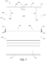
- FIG. 7 shows a front view of the bag holder of FIG. 4 with the sliding door partway open
- FIG. 8 shows a rear view of the bag holder of FIG. 4 .
- embodiments of the invention relate to bagging stations in retail stores where purchases are loaded into shopping bags, and specifically to a bagging station with a bag holder for encasing the shopping bags.
- a bagging station is a fixture in a retail store where purchased items are loaded into shopping bags so the items can be carried out of the store by the customer.
- Bagging stations are often at checkout registers where purchased items are paid for.
- Bagging stations are usually designed to store and dispense plastic bags.
- the bagging station for plastic bags will often have a bag dispenser with hooks and arms for holding stacks of plastic bags, and for hanging plastic bag arms from, to keep the plastic bag open while filling.
- the bag dispensers are often mounted to center sections that set on a rotating platform to create a carousel-type bagging station.
- the rotating platform has a number of bag dispensers, which are rotated as bags are filled to make loading and removing shopping bags efficient and easy.
- bag dispensers are not covered, which can lead to a mess if shopping bags fall off the bag dispenser.
- bags are sometimes stolen from the bag dispenser because it is easy to grab a stack of shopping bags from the bag dispenser. What is needed is a bag holder for a bagging station that encases the shopping bags and yet is still easy to use and dispense shopping bags.
- a bagging station for a retail store that includes a center section and at least one bag holder coupled to the center section.
- the center section sets on a rotating platform and holds a number of bag holders with bag dispensers.
- the center section rotates to so that access to each bag holder and bag dispenser is convenient.
- Each bag holder has a bag dispenser encased in a rectangular shaped box.
- the bag dispenser holds and dispenses shopping bags.
- the rectangular shaped box holds the bag dispenser and the shopping bags hung on the bag dispenser.
- the box has an open front that can be covered by a sliding door.
- the sliding door is flexible and slides between an open position and a closed position. In the closed position the sliding door covers the open front.
- the sliding door In the open position the sliding door does not cover the open front, but slides out of the way and retracts into the rectangular shaped box. With the sliding door in the open position, the shopping bags hanging from the bag dispenser are easily accessible and can be filled with products and dispensed. With the sliding door in the closed position, the bag dispenser and the shopping bags hanging from the bag dispenser are encased in the rectangular box and are not easily accessible. Shopping bags are protected from falling off or being wrongly removed from the bag dispenser when the sliding door is in the closed position.
- FIG. 1 through FIG. 3 shows a bagging station 208 for a retail store.
- Bagging station 208 includes a number of bag holders 210 that each hold at least one shopping bag 212 .
- Bagging station 208 includes a center section 203 that sets on a rotating platform 201 .
- Center section 203 is triangular shaped in top view in this embodiment (see FIG. 3 ), with three solid center section side walls 204 , 206 , and 207 .
- Each of side walls 204 , 206 , and 207 have two bag holders 210 coupled to it, where each bag holder 210 holds at least one shopping bag 212 .
- FIG. 1 shows a front perspective view of bagging station 208 showing two bag holders 210 coupled to each of center section side walls 204 and 206 .
- FIG. 2 shows a side view of bagging station 208 , showing two bag holders 210 coupled to center section side wall 206 .
- one bag holder 210 has a sliding door 250 in a closed position 244
- the other bag holder 210 has a sliding door 250 in an open position 242 .
- FIG. 3 shows a top view of bagging station 208 with two bag holders 210 coupled to each of center section side walls 204 , 206 , and 207 .
- Center section 203 rotates with rotating platform 201 so that each bag holder 210 can be conveniently accessed by a cashier or customer.
- Each bag holder 210 holds and dispenses shopping bags 212 .
- Bagging station 208 in the embodiment shown in the figures, includes six bag holders 210 , two on each of center section side walls 204 , 206 , and 207 , but this is not meant to be limiting. Bagging station 208 can include any number of bag holders 210 .
- FIG. 4 through FIG. 8 show details of bag holder 210 .
- FIG. 4 shows a front perspective view of bag holder 210 with sliding door 250 in closed position 244 .
- FIG. 5 shows a bottom perspective view of bag holder 210 with sliding door 250 in open position 242 .
- FIG. 6 shows a side cutaway view of bag holder 210 with sliding door 250 in closed position 244 .
- FIG. 7 shows a front view of bag holder 210 with sliding door 250 in a position partway between open position 242 and closed position 244 .
- FIG. 8 shows a rear view of bag holder 210 .
- Bag holder 210 is used for holding at least one shopping bag 212 .
- Each bag holder 210 is coupled to center section 203 , specifically one of the solid center section side walls 204 , 206 and 207 .
- Bag holder 210 holds and dispenses shopping bags 212 at bagging station 208 .
- Bag holder 210 includes a rectangular shaped box 213 , sliding door 250 , a bag holder hook 222 , a first and a second handle holder hook 224 and 226 , and a first and a second knob 260 and 262 .
- Bag holder hook 222 and handle holder hooks 224 and 226 are inside of box 213 for hanging shopping bag 212 from.
- Sliding door 250 is coupled to rectangular box 213 and slides between open position 242 and closed position 244 .
- bag holder 210 holds and dispenses shopping bags 212 .
- bag holder 210 encases shopping bags 212 and keeps shopping bags 212 secure.
- Bag holder 210 includes first knob 260 and second knob 262 that are used to open and close sliding door 250 .
- Rectangular shaped box 213 includes a back plate 214 , a top plate 230 , a bottom plate 232 , a first side plate 234 and a second side plate 236 .
- Back plate 214 is the back of box 213
- top plate 230 , bottom plate 232 , first side plate 234 and second side plate 236 are the sides of box 213 .
- Rectangular shaped box 213 has an open front 240 .
- Box 213 is rectangular shaped, with top plate 230 coupled to a back plate top edge 215 , as shown in FIG. 4 and FIG. 8 .
- Top plate 230 is perpendicular to back plate 214 .
- Bottom plate 232 is coupled to a back plate bottom edge 216 , as shown in FIG. 5 and FIG.
- Bottom plate 232 is perpendicular to back plate 214 .
- First side plate 234 is coupled to a back plate first side edge 217 , as shown in FIG. 4 and FIG. 8 .
- First side plate 234 is perpendicular to back plate 214 .
- Second side plate 236 is coupled to a back plate second side edge 218 , as shown in FIG. 5 and FIG. 8 .
- Second side plate 236 is perpendicular to back plate 214 .
- Bag holder 210 includes bag holder hook 222 and two handle holder hooks, first handle holder hook 224 and second handle holder hook 226 , as shown in FIG. 2 , FIG. 5 , FIG. 6 , and FIG. 7 .
- Bag holder hook 222 and first and second handle holder hooks 224 and 226 are used to hang at least one shopping bag 212 from, so that shopping bags 212 can be held and dispensed by bag holder hook 222 , first handle holder hook 224 and second handle holder hook 226 .
- Shopping bags 212 are usually hung from bag holder hook 222 by their center hole, with each of the two handles hung from either first handle holder hook 224 or second handle holder hook 226 , as seen in FIG. 1 and FIG.
- each shopping bag 212 can be filled with items and then removed from bag holder 210 .
- a bag 212 is filled by pulling away the front side of shopping bag 212 from the rear side of shopping bag 212 , leaving shopping bag 212 hung from bag holder hook 222 in an open position. Items are placed in shopping bag 212 until shopping bag 212 is full. Shopping bag 212 is then removed from bag holder hook 222 and first and second handle holder hook 224 and 226 to be removed from the retail store. If more items need to be bagged, a new shopping bag 212 is opened, filled, and dispensed.
- Bag holder hook 222 and first and second handle holder hooks 224 and 226 are coupled to an inner surface of rectangular shaped box 213 so that shopping bags 212 hung from bag holder hook 222 and first and second handle holder hooks 224 and 226 hang inside of bag holder 210 .
- Bag holder hook 222 and first and second handle holder hooks 224 and 226 are located near top plate 230 of bag holder 210 so that bags 212 hang inside of bag holder 210 .
- Bag holder hook 222 is located about halfway between first and second side plates 234 and 236 , with first and second handle holder hooks 224 and 226 on either side of bag holder hook 222 , as shown in FIG. 2 , FIG. 5 , FIG. 6 , and FIG.
- bag holder hook 222 and first and second handle holder hooks 224 and 226 are coupled to a top plate inner surface 231 , as shown in FIG. 5 and FIG. 6 , but this is not meant to be limiting.
- bag holder hook 222 and first and second handle holder hooks 224 and 226 are coupled to a back plate front surface 219 .
- bag holder hook 222 and first and second handle holder hooks 224 and 226 are coupled to other inner surfaces of box 213 .
- Sliding door 250 is coupled to rectangular box 213 .
- Sliding door 250 slides between open position 242 , and closed position 244 .
- Sliding door 250 covers open front 240 in closed position 244 .
- Sliding door 250 retracts into box 213 in open position 242 , and does not cover open front 240 in open position 242 .
- Sliding door 250 is a flexible tambour- or shutter-type door formed of thin rectangular plates of rigid material flexibly coupled together along their long axes.
- Sliding door 250 is flexible in a sliding door longitudinal direction 248 (see FIG. 6 ), and is not flexible in a sliding door latitudinal direction 249 (see FIG. 4 ).
- sliding door 250 When sliding door 250 is opened, sliding door 250 retracts into rectangular box 213 , sliding along back plate front surface 219 (see FIG. 5 and FIG. 7 ) until sliding door 250 is in open position 242 .
- Rectangular box 213 includes first knob 260 and second knob 262 .
- First and second knob 260 and 262 are each coupled to a sliding door top edge 251 , and are used to move sliding door 250 from closed position 244 to open position 242 .
- Sliding door 250 has sliding door top edge 251 ( FIG. 4 and FIG. 7 ) a sliding door bottom edge 252 ( FIG. 4 ) a sliding door first side edge 253 and a sliding door second side edge 254 .
- Sliding door 250 has a coupling rod 290 that is coupled to sliding door top edge 251 ( FIG. 7 ) parallel to sliding door latitudinal axis 249 .
- Coupling rod 290 extends along, and is coupled to, sliding door top edge 251 from sliding door first side edge 253 to sliding door second side edge 254 .
- Coupling rod 290 extends out from sliding door first side edge 253 and through a first track slot 270 in first side plate 234 , see FIG. 4 .
- First knob 260 is coupled to a coupling rod first end 292 of coupling rod 290 , as shown in FIG. 4 and FIG. 7 .
- First knob 260 is outside of rectangular box 213 adjacent a first side plate outer surface 235 , see FIG. 4 .
- First knob 260 is used to move sliding door 250 between open position 242 and closed position 244 .
- Coupling rod 290 extends out from sliding door second side edge 254 and through a second track slot 280 in second side plate 236 , see FIG. 5 .
- Second knob 262 is coupled to a coupling rod second end 294 of coupling rod 290 , as shown in FIG. 5 and FIG. 7 .
- Second knob 262 is outside of rectangular box 213 adjacent a second side plate outer surface 237 , see FIG. 5 . Second knob 262 is used to move sliding door 250 between open position 242 and closed position 244
- Bag holder 210 includes first track slot 270 and second track slot 280 .
- First and second track slot 270 and 280 are slots in rectangular box 213 that provide a path for coupling rod 290 to move through as sliding door 250 opens and closes.
- First track slot 270 is an elongate hole through first side plate 234 extending essentially longitudinally through first side plate 234 from a first track slot first end 271 to a first track slot second end 272 that opposes first track slot first end 271 , as shown in FIG. 4 .
- Coupling rod 290 extends through first track slot 270 to couple first knob 260 to sliding door 250 .
- Coupling rod 290 slides along first track slot 270 as sliding door 250 opens and closes.
- First track slot 270 has two sections, a first track slot first section 273 , a first track slot second section 275 , and a first track slot bend 274 .
- First track slot first section 273 extends from first track slot first end 271 to first track slot bend 274 , as shown in FIG. 4 .
- First track slot first section 273 is adjacent a first side plate front edge 277 .
- Coupling rod 290 slides long first track slot first section 273 as sliding door 250 slides from closed position 244 to almost open position, where sliding door top edge 251 is near bottom plate 232 .
- First track slot first section 273 is parallel to sliding door longitudinal axis 248 .
- First track slot second section 275 extends from first track slot bend 274 to first track slot second end 272 , as shown in FIG. 4 .
- First track slot second section 275 is adjacent a first side plate bottom edge 278 .
- Coupling rod 290 slides long first track slot second section 275 as sliding door top edge 251 slides from the almost open position to open position 242 , where sliding door top edge 251 is near back plate 214 and sliding door 250 is fully retracted into box 213 . In the fully retracted position, which is open position 242 , sliding door 250 is laying along back plate front surface 219 .
- First track slot second section 275 is parallel to, and adjacent to, first side plate bottom edge 278 .
- Second track slot 280 is an elongate hole through second side plate 236 extending essentially longitudinally through second side plate 236 from a second track slot first end 281 to a second track slot second end 282 that opposes second track slot first end 281 , as shown in FIG. 5 .
- Coupling rod 290 extends through second track slot 280 to couple second knob 262 to sliding door 250 .
- Coupling rod 290 slides along second track slot 280 as sliding door 250 opens and closes.
- Second track slot 280 has two sections, a second track slot first section 283 , a second track slot second section 285 , and a second track slot bend 284 .
- Second track slot first section 283 extends from second track slot first end 281 to second track slot bend 284 , as shown in FIG.
- Second track slot first section 283 is adjacent a second side plate front edge 287 .
- Coupling rod 290 slides long second track slot first section 283 as sliding door top edge 251 slides from closed position 244 to an almost open position, where sliding door top edge 251 is near bottom plate 232 .
- Second track slot first section 283 is parallel to sliding door longitudinal axis 248 .
- Second track slot second section 285 extends from second track slot bend 284 to second track slot second end 282 , as shown in FIG. 5 .
- Second track slot second section 285 is adjacent a second side plate bottom edge 288 .
- Coupling rod 290 slides long second track slot second section 285 as sliding door top edge 251 slides from the almost open position to open position 242 , where sliding door top edge 251 is near back plate 214 and sliding door 250 is fully retracted into box 213 . In the fully retracted position, which is open position 242 , sliding door 250 is laying along back plate front surface 219 .
- Second track slot second section 285 is parallel to, and adjacent to, first side plate bottom edge 288 .
- Bag holder 210 also includes a first magnet 266 and a second magnet 268 , as shown in FIG. 5 , FIG. 6 , and FIG. 7 .
- First and second magnet 266 and 268 are used to keep sliding door in closed position 244 .
- First magnet 266 is coupled to top side plate inner surface 231 , as shown in FIG. 5 and FIG. 6 .
- Second magnet 268 is coupled to sliding door top edge 251 , see FIG. 6 .
- Second magnet 268 is coupled to, and moves with, sliding door 250 . When sliding door 250 is in closed position 244 , second magnet 268 magnetically couples to first magnet 266 to hold sliding door 250 in the closed position, see FIG. 6 .
- bag holder 210 includes a lock to lock sliding door 251 in the closed position and make bag holder 210 more secure.
- the bag holder is a box that encloses a bag dispenser.
- the bag dispenser includes a bag holder hook and two handle holder hooks.
- the bag holder is mounted at the bagging station in a retail store so the bag dispenser can hold and dispense shopping bags.
- the bag holder includes a rectangular box with a sliding door front that encases the bag dispenser and the shopping bags. The sliding door slides between a closed position and an open position. In the open position, the bag dispenser is accessible at the bagging station and is used to dispense shopping bags. In the closed position, the bag dispenser and the shopping bags are enclosed in the bag holder. In the closed position, the shopping bags will not fall off the bag dispenser, or be stolen from the bag dispenser.
Landscapes
- Engineering & Computer Science (AREA)
- Mechanical Engineering (AREA)
- Auxiliary Apparatuses For Manual Packaging Operations (AREA)
Abstract
Description
Claims (17)
Priority Applications (1)
| Application Number | Priority Date | Filing Date | Title |
|---|---|---|---|
| US16/390,295 US10617236B2 (en) | 2018-05-25 | 2019-04-22 | Bagging station with shopping bag holder |
Applications Claiming Priority (2)
| Application Number | Priority Date | Filing Date | Title |
|---|---|---|---|
| US201862676491P | 2018-05-25 | 2018-05-25 | |
| US16/390,295 US10617236B2 (en) | 2018-05-25 | 2019-04-22 | Bagging station with shopping bag holder |
Publications (2)
| Publication Number | Publication Date |
|---|---|
| US20190357705A1 US20190357705A1 (en) | 2019-11-28 |
| US10617236B2 true US10617236B2 (en) | 2020-04-14 |
Family
ID=68615357
Family Applications (1)
| Application Number | Title | Priority Date | Filing Date |
|---|---|---|---|
| US16/390,295 Active US10617236B2 (en) | 2018-05-25 | 2019-04-22 | Bagging station with shopping bag holder |
Country Status (1)
| Country | Link |
|---|---|
| US (1) | US10617236B2 (en) |
Cited By (1)
| Publication number | Priority date | Publication date | Assignee | Title |
|---|---|---|---|---|
| US20220354277A1 (en) * | 2021-05-07 | 2022-11-10 | Toshiba Global Commerce Solutions Holdings Corporation | Repositionable bag-retaining device |
Families Citing this family (4)
| Publication number | Priority date | Publication date | Assignee | Title |
|---|---|---|---|---|
| US10625895B2 (en) | 2017-10-26 | 2020-04-21 | Walmart Apollo, Llc | Bag retaining fixture |
| US10610032B2 (en) | 2018-05-25 | 2020-04-07 | Walmart Apollo, Llc | Bagging station and shopping bag holder |
| US10617236B2 (en) * | 2018-05-25 | 2020-04-14 | Walmart Apollo, Llc | Bagging station with shopping bag holder |
| US11738900B2 (en) * | 2021-07-17 | 2023-08-29 | Walmart Apollo, Llc | Configurable universal bag holder |
Citations (118)
| Publication number | Priority date | Publication date | Assignee | Title |
|---|---|---|---|---|
| US94016A (en) * | 1869-08-24 | morse | ||
| US228627A (en) * | 1880-06-08 | William h | ||
| US473099A (en) | 1892-04-19 | Theodore j | ||
| US636491A (en) * | 1898-10-29 | 1899-11-07 | Charles Cohen | Rolling door for refrigerators or the like. |
| US721996A (en) | 1902-12-30 | 1903-03-03 | Leslie Combs Bunnell | Paper-bag holder. |
| US743547A (en) | 1903-07-20 | 1903-11-10 | William N Nix | Paper-bag holder. |
| US1355643A (en) | 1918-03-01 | 1920-10-12 | Bausano Peter | Wrap-holder for chair-backs |
| US1754327A (en) | 1929-03-19 | 1930-04-15 | Carl A Leonard | Paper-bag holder |
| US1845385A (en) * | 1931-04-06 | 1932-02-16 | Daemicke Company | Display case |
| US2107997A (en) * | 1934-12-19 | 1938-02-08 | Shanklin Mfg Company | Roll top box |
| US2324596A (en) | 1942-04-21 | 1943-07-20 | Quain Mark | Revolving laundry assembly unit |
| US2521604A (en) | 1948-01-29 | 1950-09-05 | Provost Amos | Towel or clothes hanger |
| US2616133A (en) | 1949-08-06 | 1952-11-04 | Peters Leo | Clothes retainer apparatus |
| US2722469A (en) * | 1952-12-29 | 1955-11-01 | Kosovsky Joseph | Teller's box |
| US2766822A (en) * | 1951-05-19 | 1956-10-16 | Ralph B Potter | Closure mechanism |
| US3055508A (en) | 1960-07-28 | 1962-09-25 | Woodrow W Reeser | Paper bag rack |
| US3175793A (en) | 1963-11-12 | 1965-03-30 | Olivia V Kennedy | Hanger for supporting open paper bags |
| US3262579A (en) | 1963-02-15 | 1966-07-26 | Reich Walter Robert | Holder of plastic for all kinds of cloths and toilet articles |
| US3294465A (en) * | 1964-12-02 | 1966-12-27 | Miller Herman Inc | Desk with tambour |
| US3424421A (en) | 1966-11-01 | 1969-01-28 | William H Kalbow | Container mounting device |
| US3434686A (en) | 1966-07-19 | 1969-03-25 | Yoshizaburo Aoi | Suspender for thin objects |
| US3628632A (en) | 1969-08-12 | 1971-12-21 | Frank Lambert | Automatic checkout counter |
| US3679096A (en) * | 1970-04-22 | 1972-07-25 | Malcolm E Musser | Bag holder and opening apparatus |
| US3747298A (en) | 1971-11-17 | 1973-07-24 | A Lieberman | Bag dispensing unit and the method of opening and removing the bags therefrom |
| US3838839A (en) | 1973-03-12 | 1974-10-01 | Monitor Mfg Co | Support bracket for refuse containers |
| US3847332A (en) | 1972-12-29 | 1974-11-12 | Y Murai | Hanger for dust bag |
| US4062170A (en) * | 1977-03-17 | 1977-12-13 | Mobil Oil Corporation | Apparatus for loading bags |
| US4085822A (en) * | 1975-12-04 | 1978-04-25 | Mobil Oil Corporation | Bag assembly and method and apparatus for loading individual bags |
| US4094415A (en) | 1973-06-21 | 1978-06-13 | Chas. O. Larson Co. | Display rack device |
| US4106734A (en) | 1977-03-29 | 1978-08-15 | Union Carbide Corporation | Bag dispenser and holder |
| US4106733A (en) | 1977-03-29 | 1978-08-15 | Union Carbide Corporation | Bag dispenser and holder |
| US4143845A (en) | 1978-01-03 | 1979-03-13 | Harris Mary A | Detachable support members |
| US4155458A (en) * | 1978-02-02 | 1979-05-22 | Moline Brian F | Large tool security storage system |
| US4171150A (en) * | 1977-04-04 | 1979-10-16 | Ab Gustavsberg | Mountable storage furniture |
| US4217012A (en) * | 1978-11-27 | 1980-08-12 | Fellowes Manufacturing Company | Storage unit |
| US4289242A (en) | 1979-08-31 | 1981-09-15 | Kenyon David L | Display security device |
| US4398689A (en) | 1981-04-30 | 1983-08-16 | Mobil Oil Corporation | Apparatus for loading bags |
| US4498652A (en) | 1983-07-29 | 1985-02-12 | Malik James J | Wire rack for plastic bag |
| US4600254A (en) * | 1983-07-18 | 1986-07-15 | Steelcase Canada Ltd. | Sliding door having pinion and idler wheel |
| US4657318A (en) * | 1984-06-08 | 1987-04-14 | Kimball International, Inc. | Cabinet having door braking assembly |
| US4696522A (en) * | 1986-05-09 | 1987-09-29 | Devoke Co. | Cabinet for microcomputer components |
| US4771966A (en) | 1987-11-02 | 1988-09-20 | Anderson Carl J | Paper towel holder |
| US4785971A (en) * | 1985-05-06 | 1988-11-22 | Konarik Michael A | Bag storage and dispensing apparatus |
| US4793665A (en) * | 1987-04-02 | 1988-12-27 | Wright Line Inc. | Storing and dispensing system |
| US4826022A (en) | 1988-04-20 | 1989-05-02 | Plastic Development, Inc. | Display panel assembly |
| USRE33122E (en) | 1977-03-17 | 1989-12-05 | Mobil Oil Corporation | Apparatus for loading bags |
| US5012994A (en) | 1989-04-24 | 1991-05-07 | Richard Keefe | Variable width bag holder |
| US5054728A (en) | 1990-09-12 | 1991-10-08 | Nigro Jr Philip | Pegboard hanger |
| US5131499A (en) * | 1991-08-02 | 1992-07-21 | Hoar Bruce E | Retail store checkout device |
| US5184728A (en) * | 1991-12-20 | 1993-02-09 | Bpi Environmental, Inc. | Bag dispensing system |
| US5255970A (en) * | 1992-05-26 | 1993-10-26 | Theosabrata Yos S | Storage cabinet |
| US5269416A (en) * | 1992-01-08 | 1993-12-14 | Polytec Packaging | Rack for dispensing dual tab merchandising bag |
| US5295743A (en) * | 1991-09-06 | 1994-03-22 | Dasco Data Products Limited | Secure cabinets |
| US5399010A (en) * | 1992-12-01 | 1995-03-21 | Herman Miller, Inc. | Flipper door |
| US5407170A (en) | 1992-06-25 | 1995-04-18 | Snap-On Incorporated | Lockable equipment hanger assembly |
| US5462178A (en) | 1994-06-13 | 1995-10-31 | Sagaz Industries, Inc. | Revolving display stand |
| US5467572A (en) | 1992-04-01 | 1995-11-21 | Epi Packaging Technologies, Inc. | Bagging system |
| US5524979A (en) * | 1994-06-09 | 1996-06-11 | Kimball International, Inc. | Overhead storage mechanism |
| US5632409A (en) * | 1995-10-20 | 1997-05-27 | Raghunanan; Cheryl J. | Plastic bag holder |
| US5803563A (en) * | 1997-07-11 | 1998-09-08 | National Products, Incorporated | Cabinet with removable tambour door |
| US5885002A (en) | 1997-11-03 | 1999-03-23 | Reiss; Jean K. | Recycling apparatus and system |
| US5964060A (en) | 1998-11-12 | 1999-10-12 | Furlong; Gregory S. | Door with movable lower block |
| US20020000504A1 (en) | 1998-01-12 | 2002-01-03 | Roger A Bayne | Christmas lights holder |
| US6474478B1 (en) | 1999-11-03 | 2002-11-05 | Alpha Security Products, Inc. | Security device for preventing rapid removal of merchandise |
| US6491218B2 (en) | 2000-12-21 | 2002-12-10 | Wal-Mart Stores, Inc. | Methods and apparatus for improved register checkout |
| US6550583B1 (en) | 2000-08-21 | 2003-04-22 | Optimal Robotics Corp. | Apparatus for self-serve checkout of large order purchases |
| US20030168378A1 (en) * | 2002-03-06 | 2003-09-11 | Au Kinsen Ka Fai | Rail-track display box |
| US6622979B2 (en) | 2001-03-29 | 2003-09-23 | Southern Imperial, Inc. | Stem and scan locking hooks |
| US20040112850A1 (en) | 2002-12-16 | 2004-06-17 | Jordan Mary E. | Holder for plastic and paper bags |
| US20050114216A1 (en) | 2003-11-24 | 2005-05-26 | Royston Llc | Bagging carousel |
| US20050258177A1 (en) | 2004-04-13 | 2005-11-24 | Antonio Woodson | Trash bag holder or dispenser for attaching to a trash receptacle and a trash receptacle comprising same |
| US20060021956A1 (en) * | 2004-01-20 | 2006-02-02 | Hilex Poly Co., Llc | Dispensing apparatus for plastic bags |
| US7114650B2 (en) | 2002-01-04 | 2006-10-03 | Sherrod George L | Retail products storage and dispensing apparatus and method |
| WO2006130911A1 (en) | 2005-06-08 | 2006-12-14 | Majek Automation Pty. Ltd. | A sorting apparatus |
| US7172092B2 (en) * | 2003-07-21 | 2007-02-06 | Simplehuman Llc | Upright container for storing and dispensing bags |
| US20070176058A1 (en) * | 2005-03-01 | 2007-08-02 | Broadway Kleer-Guard Corp. | Bag dispenser |
| US20070181753A1 (en) | 2006-02-07 | 2007-08-09 | Herlands Marc S | Trash bag holder |
| US7516820B1 (en) | 2008-01-25 | 2009-04-14 | International Business Machines Corporation | Collapsible multiple arm bag holder for a retail checkout station |
| US20090206091A1 (en) * | 2008-02-19 | 2009-08-20 | Hoffmann Roy W | Shopping bag storage and dispensing unit |
| US20090289019A1 (en) | 2008-05-23 | 2009-11-26 | Alvarado Rafael A | Assembly for dispensing plastic bags |
| US20100012793A1 (en) | 2006-07-21 | 2010-01-21 | Bu-Kyoung Sung | Hanger unit and collecting box with it |
| US20100021088A1 (en) | 2008-07-25 | 2010-01-28 | Hilex Poly Co., Llc | Reusable Shopping Bag |
| US20100096514A1 (en) | 2008-10-16 | 2010-04-22 | International Business Machines Corporation | Bag holder |
| US20100148019A1 (en) | 2008-12-17 | 2010-06-17 | Ebrahim Simhaee | Compact multi-rack t-shirt bag carousel |
| US7753588B2 (en) | 2003-09-15 | 2010-07-13 | Superbag Corp. | Bag, bag pack, and bag dispensing system |
| US7784625B2 (en) * | 2006-09-20 | 2010-08-31 | Rubbermaid Incorporated | Storage article organizer |
| US20100314507A1 (en) | 2009-06-11 | 2010-12-16 | Toni Laitila | Adjustable Bag Retaining Apparatus |
| US7866546B1 (en) | 2006-04-21 | 2011-01-11 | Pan-Oston | Automated checkout unit and method of use thereof |
| US7882964B2 (en) | 2007-08-01 | 2011-02-08 | Frito-Lay North America, Inc. | Apparatus and method for utilizing a gravity feed hanger |
| US20110266092A1 (en) | 2010-04-30 | 2011-11-03 | HEB Grocery Company, LP. | Checkstand and Method |
| US20120118839A1 (en) * | 2010-11-16 | 2012-05-17 | Daniel Brian Tan | Bag dispenser rack |
| USD665193S1 (en) * | 2011-05-26 | 2012-08-14 | Jack Huffey | Secure TV enclosure design |
| US8256644B2 (en) * | 2005-09-20 | 2012-09-04 | Sca Hygiene Products Ab | Dispenser |
| US8359722B2 (en) | 2010-01-18 | 2013-01-29 | Andre Claude Polizzi | Magnetic repair kit for latches and mailbox latch repair method |
| US8400324B1 (en) | 2011-11-02 | 2013-03-19 | Arthur W Jaeger | Apparatus for alerting shoppers at a checkout register |
| US20130223766A1 (en) | 2012-02-24 | 2013-08-29 | T.C. Manufacturing Company, Inc. | Plastic bag with easy open means, system for opening bags and method of manufacture |
| US20130259405A1 (en) | 2012-04-02 | 2013-10-03 | R2 Design Lab, Inc. | Lawn bag apparatus |
| US20130284756A1 (en) * | 2011-09-22 | 2013-10-31 | Ruth Springer | Pet waste bag dispenser |
| US8584982B2 (en) | 2009-04-23 | 2013-11-19 | Doyle W. Eakin | Apparatus for covering rolled paper products and dispensing fragrance |
| US8678281B2 (en) | 2011-11-22 | 2014-03-25 | International Business Machines Corporation | RFID scanning system and shopping bag with integrated RFID loop antenna |
| US8707626B2 (en) | 2012-08-13 | 2014-04-29 | Matthew H. Martin | Magnetic system for supporting a sliding closure |
| US20150048039A1 (en) | 2013-08-14 | 2015-02-19 | Laicor Fixtures Inc. | Multi-purpose bag rack |
| US9101232B1 (en) | 2014-07-09 | 2015-08-11 | Kurt H. Newman | Indicating apparatus and system for carousel bagging rack |
| US20170020307A1 (en) | 2015-07-23 | 2017-01-26 | Ronald A. Davis, Jr. | Bag holder apparatus and method |
| US20170055727A1 (en) * | 2015-08-25 | 2017-03-02 | Stephanie Tan | Hanging Bag Dispenser |
| JP6096712B2 (en) | 2014-05-20 | 2017-03-15 | 日産スチール工業株式会社 | Plastic bag holder |
| US9622598B1 (en) * | 2015-07-23 | 2017-04-18 | Ronald A. Davis, Jr. | Bag holder apparatus and method |
| US20170217621A1 (en) | 2016-01-29 | 2017-08-03 | Wal-Mart Stores, Inc. | Bagging station for filling paper-type bags |
| US9750356B2 (en) | 2013-09-19 | 2017-09-05 | Stephanie Tan | Single drawer dispenser rack |
| US20170280900A1 (en) | 2016-03-30 | 2017-10-05 | Wal-Mart Stores, Inc. | Bagging station bagging clip |
| US20170325603A1 (en) | 2015-12-22 | 2017-11-16 | Wal-Mart Stores, Inc. | Bagging station support frame and method of forming the same |
| US20170354274A1 (en) | 2016-06-14 | 2017-12-14 | Wal-Mart Stores, Inc. | Modular bagging apparatus for weight scale |
| US20180049565A1 (en) | 2016-08-19 | 2018-02-22 | Wal-Mart Stores, Inc. | Self-checkout station air circulation |
| US20180065770A1 (en) | 2016-09-08 | 2018-03-08 | Wal-Mart Stores, Inc. | Bag retaining fixture |
| US20180170597A1 (en) | 2016-12-16 | 2018-06-21 | Wal-Mart Stores, Inc. | Bagging clip tool and method of forming the same |
| US20190127103A1 (en) | 2017-10-26 | 2019-05-02 | Walmart Apollo, Llc | Bag retaining fixture |
| US20190231096A1 (en) * | 2018-01-26 | 2019-08-01 | Walmart Apollo, Llc | Shopping bag distribution station |
| US20190357705A1 (en) * | 2018-05-25 | 2019-11-28 | Walmart Apollo, Llc | Bagging station with shopping bag holder |
-
2019
- 2019-04-22 US US16/390,295 patent/US10617236B2/en active Active
Patent Citations (125)
| Publication number | Priority date | Publication date | Assignee | Title |
|---|---|---|---|---|
| US94016A (en) * | 1869-08-24 | morse | ||
| US228627A (en) * | 1880-06-08 | William h | ||
| US473099A (en) | 1892-04-19 | Theodore j | ||
| US636491A (en) * | 1898-10-29 | 1899-11-07 | Charles Cohen | Rolling door for refrigerators or the like. |
| US721996A (en) | 1902-12-30 | 1903-03-03 | Leslie Combs Bunnell | Paper-bag holder. |
| US743547A (en) | 1903-07-20 | 1903-11-10 | William N Nix | Paper-bag holder. |
| US1355643A (en) | 1918-03-01 | 1920-10-12 | Bausano Peter | Wrap-holder for chair-backs |
| US1754327A (en) | 1929-03-19 | 1930-04-15 | Carl A Leonard | Paper-bag holder |
| US1845385A (en) * | 1931-04-06 | 1932-02-16 | Daemicke Company | Display case |
| US2107997A (en) * | 1934-12-19 | 1938-02-08 | Shanklin Mfg Company | Roll top box |
| US2324596A (en) | 1942-04-21 | 1943-07-20 | Quain Mark | Revolving laundry assembly unit |
| US2521604A (en) | 1948-01-29 | 1950-09-05 | Provost Amos | Towel or clothes hanger |
| US2616133A (en) | 1949-08-06 | 1952-11-04 | Peters Leo | Clothes retainer apparatus |
| US2766822A (en) * | 1951-05-19 | 1956-10-16 | Ralph B Potter | Closure mechanism |
| US2722469A (en) * | 1952-12-29 | 1955-11-01 | Kosovsky Joseph | Teller's box |
| US3055508A (en) | 1960-07-28 | 1962-09-25 | Woodrow W Reeser | Paper bag rack |
| US3262579A (en) | 1963-02-15 | 1966-07-26 | Reich Walter Robert | Holder of plastic for all kinds of cloths and toilet articles |
| US3175793A (en) | 1963-11-12 | 1965-03-30 | Olivia V Kennedy | Hanger for supporting open paper bags |
| US3294465A (en) * | 1964-12-02 | 1966-12-27 | Miller Herman Inc | Desk with tambour |
| US3434686A (en) | 1966-07-19 | 1969-03-25 | Yoshizaburo Aoi | Suspender for thin objects |
| US3424421A (en) | 1966-11-01 | 1969-01-28 | William H Kalbow | Container mounting device |
| US3628632A (en) | 1969-08-12 | 1971-12-21 | Frank Lambert | Automatic checkout counter |
| US3679096A (en) * | 1970-04-22 | 1972-07-25 | Malcolm E Musser | Bag holder and opening apparatus |
| US3747298A (en) | 1971-11-17 | 1973-07-24 | A Lieberman | Bag dispensing unit and the method of opening and removing the bags therefrom |
| US3847332A (en) | 1972-12-29 | 1974-11-12 | Y Murai | Hanger for dust bag |
| US3838839A (en) | 1973-03-12 | 1974-10-01 | Monitor Mfg Co | Support bracket for refuse containers |
| US4094415A (en) | 1973-06-21 | 1978-06-13 | Chas. O. Larson Co. | Display rack device |
| US4085822A (en) * | 1975-12-04 | 1978-04-25 | Mobil Oil Corporation | Bag assembly and method and apparatus for loading individual bags |
| US4062170A (en) * | 1977-03-17 | 1977-12-13 | Mobil Oil Corporation | Apparatus for loading bags |
| USRE33122E (en) | 1977-03-17 | 1989-12-05 | Mobil Oil Corporation | Apparatus for loading bags |
| US4106733A (en) | 1977-03-29 | 1978-08-15 | Union Carbide Corporation | Bag dispenser and holder |
| US4106734A (en) | 1977-03-29 | 1978-08-15 | Union Carbide Corporation | Bag dispenser and holder |
| US4171150A (en) * | 1977-04-04 | 1979-10-16 | Ab Gustavsberg | Mountable storage furniture |
| US4143845A (en) | 1978-01-03 | 1979-03-13 | Harris Mary A | Detachable support members |
| US4155458A (en) * | 1978-02-02 | 1979-05-22 | Moline Brian F | Large tool security storage system |
| US4217012A (en) * | 1978-11-27 | 1980-08-12 | Fellowes Manufacturing Company | Storage unit |
| US4289242A (en) | 1979-08-31 | 1981-09-15 | Kenyon David L | Display security device |
| US4398689A (en) | 1981-04-30 | 1983-08-16 | Mobil Oil Corporation | Apparatus for loading bags |
| US4600254A (en) * | 1983-07-18 | 1986-07-15 | Steelcase Canada Ltd. | Sliding door having pinion and idler wheel |
| US4498652A (en) | 1983-07-29 | 1985-02-12 | Malik James J | Wire rack for plastic bag |
| US4657318A (en) * | 1984-06-08 | 1987-04-14 | Kimball International, Inc. | Cabinet having door braking assembly |
| US4785971A (en) * | 1985-05-06 | 1988-11-22 | Konarik Michael A | Bag storage and dispensing apparatus |
| US4696522A (en) * | 1986-05-09 | 1987-09-29 | Devoke Co. | Cabinet for microcomputer components |
| US4793665A (en) * | 1987-04-02 | 1988-12-27 | Wright Line Inc. | Storing and dispensing system |
| US4771966A (en) | 1987-11-02 | 1988-09-20 | Anderson Carl J | Paper towel holder |
| US4826022A (en) | 1988-04-20 | 1989-05-02 | Plastic Development, Inc. | Display panel assembly |
| US5012994A (en) | 1989-04-24 | 1991-05-07 | Richard Keefe | Variable width bag holder |
| US5054728A (en) | 1990-09-12 | 1991-10-08 | Nigro Jr Philip | Pegboard hanger |
| US5131499A (en) * | 1991-08-02 | 1992-07-21 | Hoar Bruce E | Retail store checkout device |
| US5295743A (en) * | 1991-09-06 | 1994-03-22 | Dasco Data Products Limited | Secure cabinets |
| US5184728A (en) * | 1991-12-20 | 1993-02-09 | Bpi Environmental, Inc. | Bag dispensing system |
| US5269416A (en) * | 1992-01-08 | 1993-12-14 | Polytec Packaging | Rack for dispensing dual tab merchandising bag |
| US5467572A (en) | 1992-04-01 | 1995-11-21 | Epi Packaging Technologies, Inc. | Bagging system |
| US5255970A (en) * | 1992-05-26 | 1993-10-26 | Theosabrata Yos S | Storage cabinet |
| US5407170A (en) | 1992-06-25 | 1995-04-18 | Snap-On Incorporated | Lockable equipment hanger assembly |
| US5399010A (en) * | 1992-12-01 | 1995-03-21 | Herman Miller, Inc. | Flipper door |
| US5524979A (en) * | 1994-06-09 | 1996-06-11 | Kimball International, Inc. | Overhead storage mechanism |
| US5462178A (en) | 1994-06-13 | 1995-10-31 | Sagaz Industries, Inc. | Revolving display stand |
| US5632409A (en) * | 1995-10-20 | 1997-05-27 | Raghunanan; Cheryl J. | Plastic bag holder |
| US5803563A (en) * | 1997-07-11 | 1998-09-08 | National Products, Incorporated | Cabinet with removable tambour door |
| US5885002A (en) | 1997-11-03 | 1999-03-23 | Reiss; Jean K. | Recycling apparatus and system |
| US20020000504A1 (en) | 1998-01-12 | 2002-01-03 | Roger A Bayne | Christmas lights holder |
| US5964060A (en) | 1998-11-12 | 1999-10-12 | Furlong; Gregory S. | Door with movable lower block |
| US6474478B1 (en) | 1999-11-03 | 2002-11-05 | Alpha Security Products, Inc. | Security device for preventing rapid removal of merchandise |
| US6550583B1 (en) | 2000-08-21 | 2003-04-22 | Optimal Robotics Corp. | Apparatus for self-serve checkout of large order purchases |
| US6491218B2 (en) | 2000-12-21 | 2002-12-10 | Wal-Mart Stores, Inc. | Methods and apparatus for improved register checkout |
| US6622979B2 (en) | 2001-03-29 | 2003-09-23 | Southern Imperial, Inc. | Stem and scan locking hooks |
| US7114650B2 (en) | 2002-01-04 | 2006-10-03 | Sherrod George L | Retail products storage and dispensing apparatus and method |
| US20030168378A1 (en) * | 2002-03-06 | 2003-09-11 | Au Kinsen Ka Fai | Rail-track display box |
| US20040112850A1 (en) | 2002-12-16 | 2004-06-17 | Jordan Mary E. | Holder for plastic and paper bags |
| US7172092B2 (en) * | 2003-07-21 | 2007-02-06 | Simplehuman Llc | Upright container for storing and dispensing bags |
| US7753588B2 (en) | 2003-09-15 | 2010-07-13 | Superbag Corp. | Bag, bag pack, and bag dispensing system |
| US20050114216A1 (en) | 2003-11-24 | 2005-05-26 | Royston Llc | Bagging carousel |
| US20060021956A1 (en) * | 2004-01-20 | 2006-02-02 | Hilex Poly Co., Llc | Dispensing apparatus for plastic bags |
| US20050258177A1 (en) | 2004-04-13 | 2005-11-24 | Antonio Woodson | Trash bag holder or dispenser for attaching to a trash receptacle and a trash receptacle comprising same |
| US20070176058A1 (en) * | 2005-03-01 | 2007-08-02 | Broadway Kleer-Guard Corp. | Bag dispenser |
| WO2006130911A1 (en) | 2005-06-08 | 2006-12-14 | Majek Automation Pty. Ltd. | A sorting apparatus |
| US8256644B2 (en) * | 2005-09-20 | 2012-09-04 | Sca Hygiene Products Ab | Dispenser |
| US20070181753A1 (en) | 2006-02-07 | 2007-08-09 | Herlands Marc S | Trash bag holder |
| US7866546B1 (en) | 2006-04-21 | 2011-01-11 | Pan-Oston | Automated checkout unit and method of use thereof |
| US20100012793A1 (en) | 2006-07-21 | 2010-01-21 | Bu-Kyoung Sung | Hanger unit and collecting box with it |
| US7784625B2 (en) * | 2006-09-20 | 2010-08-31 | Rubbermaid Incorporated | Storage article organizer |
| US7882964B2 (en) | 2007-08-01 | 2011-02-08 | Frito-Lay North America, Inc. | Apparatus and method for utilizing a gravity feed hanger |
| US7516820B1 (en) | 2008-01-25 | 2009-04-14 | International Business Machines Corporation | Collapsible multiple arm bag holder for a retail checkout station |
| US20090206091A1 (en) * | 2008-02-19 | 2009-08-20 | Hoffmann Roy W | Shopping bag storage and dispensing unit |
| US20090289019A1 (en) | 2008-05-23 | 2009-11-26 | Alvarado Rafael A | Assembly for dispensing plastic bags |
| US20100021088A1 (en) | 2008-07-25 | 2010-01-28 | Hilex Poly Co., Llc | Reusable Shopping Bag |
| US20100096514A1 (en) | 2008-10-16 | 2010-04-22 | International Business Machines Corporation | Bag holder |
| US20100148019A1 (en) | 2008-12-17 | 2010-06-17 | Ebrahim Simhaee | Compact multi-rack t-shirt bag carousel |
| US8584982B2 (en) | 2009-04-23 | 2013-11-19 | Doyle W. Eakin | Apparatus for covering rolled paper products and dispensing fragrance |
| US20100314507A1 (en) | 2009-06-11 | 2010-12-16 | Toni Laitila | Adjustable Bag Retaining Apparatus |
| US20140138499A1 (en) | 2009-06-11 | 2014-05-22 | Laicor Fixtures, Inc. | Adjustable Bag Retaining Apparatus |
| US8359722B2 (en) | 2010-01-18 | 2013-01-29 | Andre Claude Polizzi | Magnetic repair kit for latches and mailbox latch repair method |
| US20110266092A1 (en) | 2010-04-30 | 2011-11-03 | HEB Grocery Company, LP. | Checkstand and Method |
| US20120118839A1 (en) * | 2010-11-16 | 2012-05-17 | Daniel Brian Tan | Bag dispenser rack |
| USD665193S1 (en) * | 2011-05-26 | 2012-08-14 | Jack Huffey | Secure TV enclosure design |
| US20130284756A1 (en) * | 2011-09-22 | 2013-10-31 | Ruth Springer | Pet waste bag dispenser |
| US8400324B1 (en) | 2011-11-02 | 2013-03-19 | Arthur W Jaeger | Apparatus for alerting shoppers at a checkout register |
| US8678281B2 (en) | 2011-11-22 | 2014-03-25 | International Business Machines Corporation | RFID scanning system and shopping bag with integrated RFID loop antenna |
| US20130223766A1 (en) | 2012-02-24 | 2013-08-29 | T.C. Manufacturing Company, Inc. | Plastic bag with easy open means, system for opening bags and method of manufacture |
| US20130259405A1 (en) | 2012-04-02 | 2013-10-03 | R2 Design Lab, Inc. | Lawn bag apparatus |
| US8707626B2 (en) | 2012-08-13 | 2014-04-29 | Matthew H. Martin | Magnetic system for supporting a sliding closure |
| US20150048039A1 (en) | 2013-08-14 | 2015-02-19 | Laicor Fixtures Inc. | Multi-purpose bag rack |
| US9750356B2 (en) | 2013-09-19 | 2017-09-05 | Stephanie Tan | Single drawer dispenser rack |
| JP6096712B2 (en) | 2014-05-20 | 2017-03-15 | 日産スチール工業株式会社 | Plastic bag holder |
| US9101232B1 (en) | 2014-07-09 | 2015-08-11 | Kurt H. Newman | Indicating apparatus and system for carousel bagging rack |
| US9622598B1 (en) * | 2015-07-23 | 2017-04-18 | Ronald A. Davis, Jr. | Bag holder apparatus and method |
| US9622599B2 (en) | 2015-07-23 | 2017-04-18 | Ronald A. Davis, Jr. | Bag holder apparatus and method |
| US20170020307A1 (en) | 2015-07-23 | 2017-01-26 | Ronald A. Davis, Jr. | Bag holder apparatus and method |
| US20170055727A1 (en) * | 2015-08-25 | 2017-03-02 | Stephanie Tan | Hanging Bag Dispenser |
| US9770123B2 (en) | 2015-08-25 | 2017-09-26 | Stephanie Tan | Hanging bag dispenser |
| US20170325603A1 (en) | 2015-12-22 | 2017-11-16 | Wal-Mart Stores, Inc. | Bagging station support frame and method of forming the same |
| US20170217621A1 (en) | 2016-01-29 | 2017-08-03 | Wal-Mart Stores, Inc. | Bagging station for filling paper-type bags |
| US10029815B2 (en) * | 2016-01-29 | 2018-07-24 | Walmart Apollo, Llc | Bagging station for filling paper-type bags |
| US20170280900A1 (en) | 2016-03-30 | 2017-10-05 | Wal-Mart Stores, Inc. | Bagging station bagging clip |
| US20170354274A1 (en) | 2016-06-14 | 2017-12-14 | Wal-Mart Stores, Inc. | Modular bagging apparatus for weight scale |
| US20180049565A1 (en) | 2016-08-19 | 2018-02-22 | Wal-Mart Stores, Inc. | Self-checkout station air circulation |
| US20180065770A1 (en) | 2016-09-08 | 2018-03-08 | Wal-Mart Stores, Inc. | Bag retaining fixture |
| US20180064266A1 (en) | 2016-09-08 | 2018-03-08 | Wal-Mart Stores, Inc. | Bag retaining fixture |
| US10028598B2 (en) * | 2016-09-08 | 2018-07-24 | Walmart Apollo, Llc | Bag retaining fixture |
| US10106284B2 (en) * | 2016-09-08 | 2018-10-23 | Walmart Apollo, Llc | Bag retaining fixture |
| US20180170597A1 (en) | 2016-12-16 | 2018-06-21 | Wal-Mart Stores, Inc. | Bagging clip tool and method of forming the same |
| US20190127103A1 (en) | 2017-10-26 | 2019-05-02 | Walmart Apollo, Llc | Bag retaining fixture |
| US20190231096A1 (en) * | 2018-01-26 | 2019-08-01 | Walmart Apollo, Llc | Shopping bag distribution station |
| US20190357705A1 (en) * | 2018-05-25 | 2019-11-28 | Walmart Apollo, Llc | Bagging station with shopping bag holder |
Non-Patent Citations (15)
| Title |
|---|
| 100mm metal wire clip/clipboard clip, Dongguan Taoyuan Stationary Co., Ltd., Sell.Lulusoso.com, accessed May 20, 2016; 4 pages. |
| Non-Final Office Action for U.S. Appl. No. 15/695,306, dated Apr. 18, 2018; 11 pages. |
| Non-Final Office Action in U.S. Appl. No. 15/415,026, dated Dec. 28, 2017; 8 pages. |
| Non-Final Office Action in U.S. Appl. No. 15/695,401, dated Feb. 2, 2018; 7 pages. |
| Non-Final Office Action in U.S. Appl. No. 16/143,800 dated Dec. 11, 2019; 6 pages. |
| Non-Final Office Action in U.S. Appl. No. 16/390,277 dated Sep. 24, 2019; 14 pages. |
| Notice of Allowance for U.S. Appl. No. 15/695,306, dated Jul. 23, 2018; 7 pages. |
| Notice of Allowance for U.S. Appl. No. 15/695,401, dated May 4, 2018; 8 pages. |
| Notice of Allowance in U.S. Appl. No. 15/415,026 dated May 21, 2018; 6 pages. |
| Notice of Allowance in U.S. Appl. No. 16/143,800 dated Feb. 13, 2020; 9 pages. |
| Notice of Allowance in U.S. Appl. No. 16/390,277, dated Jan. 15, 2020; 5 pages. |
| Over Door Bag Holder Waste Bin, Hang Over Kitchen Door, Reuses Shopping Bags, Klife, Ebay.com, on May 23, 2016; 4 pages. |
| Web page image 1, Dec. 29, 2015, https://www.google.co.in/imgres?imgurl=https://c1.staticflickr.com/3/2932/14248018844_89e3d89fa4_b.jpg&imgrefurl=https://www.flickr.com/photos/ieepersmedia/14248018844&h=950&w=1024&tbnid=MyLI_TOn6HIMCM:&docid=9feoV3Exk3O-4M&ei=jfyAVsbyJMPluASeoa6QBw&tbm=isch&ved=0ahUKEwiG7Z7tmv7JAhVDJI4KHZ6QC3IQMwgkKAkwCQ. |
| Web page image 2, Dec. 29, 2015, https://www.flickr.com/photos/fourstarcashiernathan/6979145827. |
| Weimaamerica, "Carousel Bagging System for WEIMA Briquette Press," YouTube.com, Apr. 15, 2009. Video. |
Cited By (2)
| Publication number | Priority date | Publication date | Assignee | Title |
|---|---|---|---|---|
| US20220354277A1 (en) * | 2021-05-07 | 2022-11-10 | Toshiba Global Commerce Solutions Holdings Corporation | Repositionable bag-retaining device |
| US12096869B2 (en) * | 2021-05-07 | 2024-09-24 | Toshiba Global Commerce Solutions Holdings Corporation | Repositionable bag-retaining device |
Also Published As
| Publication number | Publication date |
|---|---|
| US20190357705A1 (en) | 2019-11-28 |
Similar Documents
| Publication | Publication Date | Title |
|---|---|---|
| US10617236B2 (en) | Bagging station with shopping bag holder | |
| US10610032B2 (en) | Bagging station and shopping bag holder | |
| US10173708B1 (en) | Shopping cart bagging station | |
| US10028598B2 (en) | Bag retaining fixture | |
| US9265364B2 (en) | Single drawer dispenser rack | |
| US9096408B2 (en) | Clam shell bag dispenser | |
| CA2075853C (en) | Dispensing apparatus for plastic bags | |
| US10029815B2 (en) | Bagging station for filling paper-type bags | |
| US9084464B2 (en) | Case having a housing and a sliding tray | |
| US20190231096A1 (en) | Shopping bag distribution station | |
| US20170174240A1 (en) | Shopping cart bagging station and method of forming the same | |
| US10507859B2 (en) | Shopping cart bagging station | |
| CA2958358A1 (en) | Shopping cart bagging station and method of forming the same | |
| US10625895B2 (en) | Bag retaining fixture | |
| EP3782502B1 (en) | Storage bag with enhanced interior visibility | |
| US10308387B2 (en) | Bagging clip tool for a bagging station | |
| US4805969A (en) | Bag holder | |
| US20180319571A1 (en) | Garbage Bag Dispensing Assembly | |
| US10086967B2 (en) | Retractable bagging station | |
| PL180227B1 (en) | Plastic bag dispensing device and plastic bag for use with this device EN EN EN | |
| US10336358B2 (en) | Shopping cart bagging station and method of forming the same | |
| US20110203437A1 (en) | Gift wrapping storage dispenser and display | |
| US20260109532A1 (en) | Sandwich bag dispensing device | |
| CN116157335A (en) | Plastic container with cover | |
| JP3081963U (en) | Shopping bag |
Legal Events
| Date | Code | Title | Description |
|---|---|---|---|
| AS | Assignment |
Owner name: WALMART APOLLO, LLC, ARKANSAS Free format text: ASSIGNMENT OF ASSIGNORS INTEREST;ASSIGNORS:BACALLAO, YURGIS MAURO;WENDEL, CAROLYNE;SIGNING DATES FROM 20180525 TO 20180605;REEL/FRAME:048954/0529 |
|
| FEPP | Fee payment procedure |
Free format text: ENTITY STATUS SET TO UNDISCOUNTED (ORIGINAL EVENT CODE: BIG.); ENTITY STATUS OF PATENT OWNER: LARGE ENTITY |
|
| STPP | Information on status: patent application and granting procedure in general |
Free format text: NOTICE OF ALLOWANCE MAILED -- APPLICATION RECEIVED IN OFFICE OF PUBLICATIONS |
|
| STPP | Information on status: patent application and granting procedure in general |
Free format text: PUBLICATIONS -- ISSUE FEE PAYMENT RECEIVED |
|
| STCF | Information on status: patent grant |
Free format text: PATENTED CASE |
|
| MAFP | Maintenance fee payment |
Free format text: PAYMENT OF MAINTENANCE FEE, 4TH YEAR, LARGE ENTITY (ORIGINAL EVENT CODE: M1551); ENTITY STATUS OF PATENT OWNER: LARGE ENTITY Year of fee payment: 4 |