US10615548B2 - Safety power connector - Google Patents
Safety power connector Download PDFInfo
- Publication number
- US10615548B2 US10615548B2 US16/502,167 US201916502167A US10615548B2 US 10615548 B2 US10615548 B2 US 10615548B2 US 201916502167 A US201916502167 A US 201916502167A US 10615548 B2 US10615548 B2 US 10615548B2
- Authority
- US
- United States
- Prior art keywords
- section
- contact
- contacts
- normally open
- switch
- Prior art date
- Legal status (The legal status is an assumption and is not a legal conclusion. Google has not performed a legal analysis and makes no representation as to the accuracy of the status listed.)
- Expired - Fee Related
Links
- 230000007935 neutral effect Effects 0.000 claims description 89
- 230000013011 mating Effects 0.000 claims description 35
- 238000000034 method Methods 0.000 claims description 9
- 230000004913 activation Effects 0.000 claims description 8
- 235000014676 Phragmites communis Nutrition 0.000 claims description 7
- 239000000696 magnetic material Substances 0.000 claims 5
- 230000003466 anti-cipated effect Effects 0.000 description 19
- 239000004020 conductor Substances 0.000 description 12
- WABPQHHGFIMREM-UHFFFAOYSA-N lead(0) Chemical compound [Pb] WABPQHHGFIMREM-UHFFFAOYSA-N 0.000 description 11
- 230000005355 Hall effect Effects 0.000 description 9
- XEEYBQQBJWHFJM-UHFFFAOYSA-N Iron Chemical compound [Fe] XEEYBQQBJWHFJM-UHFFFAOYSA-N 0.000 description 8
- 230000006378 damage Effects 0.000 description 8
- 239000002184 metal Substances 0.000 description 6
- 229910052751 metal Inorganic materials 0.000 description 6
- 208000027418 Wounds and injury Diseases 0.000 description 5
- 208000014674 injury Diseases 0.000 description 5
- 239000000463 material Substances 0.000 description 5
- 229910000831 Steel Inorganic materials 0.000 description 4
- 230000005611 electricity Effects 0.000 description 4
- 229910052742 iron Inorganic materials 0.000 description 4
- 230000035939 shock Effects 0.000 description 4
- 239000010959 steel Substances 0.000 description 4
- 230000007246 mechanism Effects 0.000 description 3
- 238000005476 soldering Methods 0.000 description 3
- 239000003990 capacitor Substances 0.000 description 2
- 238000010586 diagram Methods 0.000 description 2
- 206010014405 Electrocution Diseases 0.000 description 1
- 240000007643 Phytolacca americana Species 0.000 description 1
- 230000001154 acute effect Effects 0.000 description 1
- 238000013459 approach Methods 0.000 description 1
- 238000010276 construction Methods 0.000 description 1
- 238000009413 insulation Methods 0.000 description 1
- 239000012212 insulator Substances 0.000 description 1
- 230000000926 neurological effect Effects 0.000 description 1
- 239000006187 pill Substances 0.000 description 1
- 238000000926 separation method Methods 0.000 description 1
Images


Classifications
-
- H—ELECTRICITY
- H01—ELECTRIC ELEMENTS
- H01R—ELECTRICALLY-CONDUCTIVE CONNECTIONS; STRUCTURAL ASSOCIATIONS OF A PLURALITY OF MUTUALLY-INSULATED ELECTRICAL CONNECTING ELEMENTS; COUPLING DEVICES; CURRENT COLLECTORS
- H01R13/00—Details of coupling devices of the kinds covered by groups H01R12/70 or H01R24/00 - H01R33/00
- H01R13/66—Structural association with built-in electrical component
- H01R13/70—Structural association with built-in electrical component with built-in switch
- H01R13/703—Structural association with built-in electrical component with built-in switch operated by engagement or disengagement of coupling parts, e.g. dual-continuity coupling part
- H01R13/7036—Structural association with built-in electrical component with built-in switch operated by engagement or disengagement of coupling parts, e.g. dual-continuity coupling part the switch being in series with coupling part, e.g. dead coupling, explosion proof coupling
-
- H—ELECTRICITY
- H01—ELECTRIC ELEMENTS
- H01R—ELECTRICALLY-CONDUCTIVE CONNECTIONS; STRUCTURAL ASSOCIATIONS OF A PLURALITY OF MUTUALLY-INSULATED ELECTRICAL CONNECTING ELEMENTS; COUPLING DEVICES; CURRENT COLLECTORS
- H01R13/00—Details of coupling devices of the kinds covered by groups H01R12/70 or H01R24/00 - H01R33/00
- H01R13/44—Means for preventing access to live contacts
- H01R13/447—Shutter or cover plate
-
- H—ELECTRICITY
- H01—ELECTRIC ELEMENTS
- H01R—ELECTRICALLY-CONDUCTIVE CONNECTIONS; STRUCTURAL ASSOCIATIONS OF A PLURALITY OF MUTUALLY-INSULATED ELECTRICAL CONNECTING ELEMENTS; COUPLING DEVICES; CURRENT COLLECTORS
- H01R13/00—Details of coupling devices of the kinds covered by groups H01R12/70 or H01R24/00 - H01R33/00
- H01R13/62—Means for facilitating engagement or disengagement of coupling parts or for holding them in engagement
- H01R13/6205—Two-part coupling devices held in engagement by a magnet
-
- H—ELECTRICITY
- H01—ELECTRIC ELEMENTS
- H01R—ELECTRICALLY-CONDUCTIVE CONNECTIONS; STRUCTURAL ASSOCIATIONS OF A PLURALITY OF MUTUALLY-INSULATED ELECTRICAL CONNECTING ELEMENTS; COUPLING DEVICES; CURRENT COLLECTORS
- H01R13/00—Details of coupling devices of the kinds covered by groups H01R12/70 or H01R24/00 - H01R33/00
- H01R13/648—Protective earth or shield arrangements on coupling devices, e.g. anti-static shielding
-
- H—ELECTRICITY
- H01—ELECTRIC ELEMENTS
- H01R—ELECTRICALLY-CONDUCTIVE CONNECTIONS; STRUCTURAL ASSOCIATIONS OF A PLURALITY OF MUTUALLY-INSULATED ELECTRICAL CONNECTING ELEMENTS; COUPLING DEVICES; CURRENT COLLECTORS
- H01R13/00—Details of coupling devices of the kinds covered by groups H01R12/70 or H01R24/00 - H01R33/00
- H01R13/66—Structural association with built-in electrical component
- H01R13/70—Structural association with built-in electrical component with built-in switch
- H01R13/703—Structural association with built-in electrical component with built-in switch operated by engagement or disengagement of coupling parts, e.g. dual-continuity coupling part
- H01R13/7036—Structural association with built-in electrical component with built-in switch operated by engagement or disengagement of coupling parts, e.g. dual-continuity coupling part the switch being in series with coupling part, e.g. dead coupling, explosion proof coupling
- H01R13/7037—Structural association with built-in electrical component with built-in switch operated by engagement or disengagement of coupling parts, e.g. dual-continuity coupling part the switch being in series with coupling part, e.g. dead coupling, explosion proof coupling making use of a magnetically operated switch
-
- H—ELECTRICITY
- H01—ELECTRIC ELEMENTS
- H01H—ELECTRIC SWITCHES; RELAYS; SELECTORS; EMERGENCY PROTECTIVE DEVICES
- H01H27/00—Switches operated by a removable member, e.g. key, plug or plate; Switches operated by setting members according to a single predetermined combination out of several possible settings
-
- H—ELECTRICITY
- H01—ELECTRIC ELEMENTS
- H01H—ELECTRIC SWITCHES; RELAYS; SELECTORS; EMERGENCY PROTECTIVE DEVICES
- H01H36/00—Switches actuated by change of magnetic field or of electric field, e.g. by change of relative position of magnet and switch, by shielding
-
- H—ELECTRICITY
- H01—ELECTRIC ELEMENTS
- H01H—ELECTRIC SWITCHES; RELAYS; SELECTORS; EMERGENCY PROTECTIVE DEVICES
- H01H36/00—Switches actuated by change of magnetic field or of electric field, e.g. by change of relative position of magnet and switch, by shielding
- H01H36/0006—Permanent magnet actuating reed switches
- H01H36/0046—Limit switches, also fail-safe operation or anti-tamper considerations
Definitions
- This invention relates to the field of electricity and more particularly to a system for improving the safety of providing household electricity.
- One way to prevent electrical injuries is to cover all outlets, for example, using plastic parts with prongs that fit into the receptacles and attempt to keep children from placing metal objects into the holes of the receptacles.
- This method is an improvement, but there are many reasons for failure, even when these covers are in use.
- parents must remove these plastic covers to insert lamp plugs, etc., sometimes forgetting to replace the plastic covers.
- harried parents will remove the plastic cover to use an outlet, then, later, are unable to find the cover and leave the outlet uncovered.
- the amount of protection any system provides to children is typically inversely proportional to the amount of effort required to maintain such a system.
- Another issue with the existing plug/outlet arrangements is strain relief.
- the existing plug/outlet arrangement often resists pulling of the plug from the outlet, especially when the lead wire is pulled at an acute angle from the plane in which the outlet is mounted (e.g. the wall). Improper pulling of the lead wire wears the interface between the lead wire and the plug, potentially removing some insulation and exposing conductors which potentially lead to electric shock.
- Power outlets typically have a hot electrical contact, a neutral electrical contact, and often a ground contact. To provide improved safety to an electric outlet, when the outlet is idle, the hot electrical potential is disconnected from the hot electrical contact and, therefore, it is more difficult for a child (or pet) to suffer from electrocution.
- a power connector (often referred to as a plug) mates with the outlet, the hot electrical potential is connected to the hot electrical contact by one or more switches for providing electrical power.
- a magnet in the power connector e.g. plug
- activates (closes) one of the switches e.g. a magnetically operated switch or a reed switch or causes a mechanical assembly to move and make contact).
- a physical feature of the power connector activates one of the switches.
- both the magnet and the physical feature are required and both switches are in series, one activated by magnetic field and the other activated by the physical feature. This makes it very difficult for a child to overcome the physical feature and the magnetic feature and, at the same time, touching the hot electrical contact.
- a simple embodiment of the disclosed invention is a standard electrical outlet that has a switch coupled to the neutral side of the outlet. The switch enables/disables flow of the hot electrical potential to the hot electrical contact such that, when the neutral prong is inserted into the neutral side of the outlet, the switch closes, allowing for flow of the hot electrical potential to the hot electrical contact.
- a child would need to insert something into the neutral side of the outlet while also inserting a metal object onto the hot side of the outlet at the same time. This alone would reduce the risk of shock and would work with legacy plugs, only requiring replacement of outlets that need protection from children.
- a safety power connector includes a male section (e.g. plug) and a female section (e.g. outlet).
- the male section has contacts for carrying electric current and one or more magnets arranged in selected polarities.
- the male section also has a centrally located protrusion (physical feature).
- the female section has a centrally located receptacle for receiving the protrusion of the male section and contacts that mate with the contacts of the male section. When the male section is absent, no electrical potential is present at the contacts of the female section (e.g. the hot electrical potential is disconnected), thereby reducing potential for an electric shock.
- a second, magnetically operated switch e.g. a reed switch or spring-loaded magnetically operated switch assembly
- sensing a magnetic field from the one or more magnets of the male section closes when the male section is against the female section, thereby providing electrical potential to the contacts of the female section (e.g. providing hot electrical potential to the hot electrical contact) that are in contact with the contacts of the male section.
- the magnets of the male section attract the female section and hold the male section to the female section. This serves as a strain relief, as the magnets are engineered to release before strain on the lead wire of the male section exceeds any strain relief that is in place for the lead wire.
- the contacts of the female section are ring-shaped allowing for any orientation of the male section with respect to the female section which is an improvement over existing receptacles that only allow for a single orientation.
- the contacts of the male section are also ring-shaped.
- a safety power connector including a male section having two or more contacts, a permanent magnet, and a protrusion; and a female section having two or more mating contacts arranged to mate with the two or more contacts of the male section when the protrusion of the male section is within a receptacle of the female section.
- the female section has a first normally open switch that is closed when the protrusion is within the receptacle and a magnetically operated switch that is closed when the permanent magnet of the male section is in range of the magnetically operated switch.
- the normally open switch and the magnetically operated switch are arranged in electrical series between a source of electric potential (hot) and one of the two or more contacts. The source of electric potential is disconnected from the one of the two or more contacts until the male section is mated with the female section.
- a safety power connector including a male section having two or more contacts, a permanent magnet, and a protrusion; and a female section having two or more mating contacts arranged to mate with the two or more contacts of the male section when the protrusion of the male section is within a receptacle of the female section.
- the female section has a first normally open switch that is closed when the protrusion is within the receptacle and a magnetically operated switch that is closed when the permanent magnet of the male section is in range of the magnetically operated switch.
- the normally open switch and the magnetically operated switch are arranged in electrical series between a source of electric potential (hot) and a hot contact of the two or more contacts. Therefore, the source of electric potential is disconnected from the hot contact of the two or more contacts until the male section is mated with the female section.
- a method of improving safety to a power outlet including providing a source of power comprising of a hot power and a neutral power and connecting the neutral power to a neutral contact of the safety power outlet.
- the hot power is then connected to a first side of a first normally open switch and a second side of the first normally open switch is connected to a first side of a second normally open switch and a second side of the second normally open switch is connected to a hot contact of the safety power outlet.
- This arrangement requires a protrusion from a male connector to close one of the first normally open switch or the second normally open switch and a magnetic field from the male connector to close the other of the first normally open switch or the second normally open switch.
- the hot power is provided to the hot contact of the safety power outlet only after the protrusion from the male connector closes one of the first normally open switch or the second normally open switch and the magnetic field from the male connector closes the other of the first normally open switch or the second normally open switch.
- a safety power connector including a male section that has two or more contacts, a permanent magnet, and a protrusion.
- a female section has two or more mating contacts arranged to mate with the two or more contacts of the male section when the protrusion of the male section is within a receptacle of the female section.
- the female section has a first normally open switch that is closed when the protrusion is within the receptacle and a magnetically operated switch that is closed when the permanent magnet of the male section is in range of the magnetically operated switch.
- the normally open switch and the magnetically operated switch are arranged in electrical series between a source of electric potential and one of the two or more contacts so that the source of electric potential is disconnected from the one of the two or more contacts until the male section is mated with the female section.
- FIG. 1 illustrates a schematic view of a safety power connector.
- FIG. 1A illustrates an alternate schematic view of a safety power connector.
- FIG. 1B illustrates an alternate schematic view of a safety power connector.
- FIG. 1C illustrates an alternate schematic view of a safety power connector.
- FIGS. 2 and 3 illustrates perspective views a female section of the safety power connector.
- FIG. 4 illustrates perspective views a male section of the safety power connector.
- FIGS. 5 and 5A illustrate schematic diagrams of the safety power connector.
- FIG. 6 illustrates a perspective view of two of the female sections of the safety power connector.
- FIG. 7 illustrates a plan view of two of the female sections of the safety power connector.
- FIG. 8 illustrates a perspective view of the two female sections of the safety power connector, one having a male section of the safety power connector and the other having a male section to standard outlet converter.
- FIG. 9 illustrates an exploded view of the male section of the safety power connector.
- FIG. 10 illustrates a cut-away view of the male section of the safety power connector.
- FIG. 11 illustrates a perspective view of the male section of the safety power connector.
- FIG. 12 illustrates an exploded view of the male section to standard outlet converter.
- FIG. 13 illustrates a cut-away view of the male section to standard outlet converter.
- FIG. 14 illustrates a front-perspective view of the male section to standard outlet converter.
- FIG. 15 illustrates a rear-perspective view of the male section to standard outlet converter.
- the safety power connector 10 has two sections, a female section 20 and a male section 40 .
- the female section 20 is connected to a source of power (not shown) while the male section 40 is typically connected to a sink of power such as a lamp, vacuum cleaner, appliance, etc.
- the female section 20 is connected to a source of power through two or more connections (three are shown).
- a ground connection 22 for connecting to ground potential
- a neutral connection 24 for connecting to neutral potential
- a hot connection 26 for connecting to the hot wire in a typical household alternating current arrangement. Note that, as stated, any number of connections are anticipated for any source of power, especially sources of power that have the potential to cause bodily harm, either alternating current or direct current.
- the ground connection 22 connects directly to a ground contact 32 and the neutral connection 24 connects directly to a neutral contact 34 . Since the ground potential and neutral potential are the safest in typical household alternating current arrangements, the ground contact 32 and neutral contact 34 are closest to the outer edge of the female section 20 , making it difficult to reach the hot contact 36 , which is located centrally to the female section 20 . In some embodiments, the ground contact 32 , the neutral contact 34 , and the hot contact 36 are concentric, circular conductive planes, enabling contact with the mating ground contact 42 , the mating neutral contact 44 , and the mating hot contact 46 in any orientation (0-360 degrees).
- At least one or two internal switches 31 / 37 of the safety power connector 10 disconnects the hot contact 36 from the hot connection 26 so that the hot potential of the typical household alternating current arrangement is not present at the hot contact 36 until mating is achieved with a male section 40 , thereby reducing the possibility that a child or pet will come into contact with the dangerous potential of the typical household alternating current arrangement.
- a first one of the one or two internal switches 31 / 37 is a manually operated, normally open switch 31 , for example, a microswitch or a mechanical assembly that is actuated by mechanical force.
- This normally open switch 31 has an actuator 33 that is physically interfaced to a receptacle 30 of the female section 20 . Therefore, the normally open switch 31 does not complete the circuit between its contacts 35 until the actuator 33 is pushed, and the actuator 33 is pushed when the protrusion 50 of the male section 40 enters the receptacle 30 of the female section 20 at a point where the mating contacts 42 / 44 / 46 of the male section 40 are very close or touching the contacts 32 / 34 / 36 of the female section 20 . Therefore, power is not provided to the hot contact 36 until the male section 40 is abutting the female section 20 .
- a second one of the one or two internal switches 31 / 37 is a magnetically actuated switch 37 (e.g. a reed relay or a mechanical assembly that moves by way of magnetic force).
- the magnetically actuated switch 37 is connected in series with the normally open switch 31 .
- the magnetically actuated switch 37 closes upon sufficient magnetic field that is supplied by one or more permanent magnets 43 that are mounted within the male section 40 when the male section 40 is in close proximity to the female section 20 .
- Safety is improved as, even it an object is pushed into the receptacle 30 far enough to actuate the actuator 33 of the normally open switch 31 , it is unlikely that there is sufficient magnetic force near to the magnetically actuated switch 37 to complete the circuit between the hot connection 26 and the hot contact 36 . Further, it is unlikely that a child playing with a magnet will find the correct spot to be close to the magnetically actuated switch 37 at the same time that the child is pushing an object into the receptacle 30 .
- the receptacle 30 and the protrusion 50 are centrally located.
- the mating ground contact 42 of the male section 40 is connected to a ground connection 52 (or directly to the ground conductor of a power cable).
- the mating neutral contact 44 of the male section 40 is connected to a neutral connection 54 (or directly to the neutral conductor of a power cable).
- the mating hot contact 46 of the male section 40 is connected to a hot connection 56 (or directly to the hot conductor of a power cable).
- additional pairs of magnetic attractors 25 / 45 are provided to hold the male section 40 to the female section 20 and/or to provide specific orientations.
- the magnetic attractors 25 of the female section 20 are magnets and the magnetic attractors 45 of the male section 40 are made of a magnetically attracted material (e.g. steel, iron).
- the magnetic attractors 25 of the female section 20 are made of a magnetically attracted material (e.g. steel, iron) and the magnetic attractors 45 of the male section 40 are magnets.
- the magnetic attractors 25 of the female section 20 and the magnetic attractors 45 of the male section 40 are magnets. In some such embodiments, pole alignment of the magnets are arranged to provide limitations of rotational orientation.
- FIG. 1A an alternate schematic view of a safety power connector 10 A is shown.
- the safety power connector 10 has two sections, a female section 20 A and a male section 40 .
- the female section 20 A is connected to a source of power (not shown) while the male section 40 is typically connected to a sink of power such as a lamp, vacuum cleaner, appliance, etc.
- the female section 20 A is connected to a source of power through two or more connections (three are shown).
- a ground connection 22 for connecting to ground potential
- a neutral connection 24 for connecting to neutral potential
- a hot connection 26 for connecting to the hot wire in a typical household alternating current arrangement. Note that, as stated, any number of connections are anticipated for any source of power, especially sources of power that have the potential to cause bodily harm, either alternating current or direct current.
- the ground connection 22 connects directly to a ground contact 32 and the neutral connection 24 connects directly to a neutral contact 34 . Since the ground potential and neutral potential are the safest in typical household alternating current arrangements, the ground contact 32 and neutral contact 34 are preferably closest to the outer edge of the female section 20 A, making it difficult to reach the hot contact 36 , which is located centrally to the female section 20 A. In some embodiments, the ground contact 32 , the neutral contact 34 , and the hot contact 36 are concentric, circular conductive planes, enabling contact with the mating ground contact 42 , the mating neutral contact 44 , and the mating hot contact 46 of the male section 40 in any orientation (0-360 degrees).
- the one or two internal switches 31 / 37 A of the safety power connector 10 disconnect the hot contact 36 from the hot connection 26 so that the hot potential of the typical household alternating current arrangement is not present at the hot contact 36 until mating is achieved with a male section 40 , thereby reducing the possibility that a child or pet will come into contact with the dangerous potential of the typical household alternating current arrangement.
- a first one of the one or two internal switches 31 / 37 is a manually operated normally open switch 31 .
- This normally open switch 31 has an actuator 33 that is physically interfaced to a receptacle 30 of the female section 20 . Therefore, the normally open switch 31 does not complete the circuit between its contacts 35 until the actuator 33 is pushed, and the actuator 33 is pushed when the protrusion 50 of the male section 40 enters the receptacle 30 of the female section 20 at a point where the mating contacts 42 / 44 / 46 of the male section 40 are very close or touching the contacts 32 / 34 / 36 of the female section 20 . Therefore, power is not provided to the hot contact 36 until the male section 40 is abutting the female section 20 .
- a second one of the one or two internal switches 31 / 37 A is a set of relay contacts 37 A.
- a Hall Effect device 80 is magnetically actuated and, when in presence of a magnetic field, the Hall Effect device 80 allows the pull-up resistor 182 to saturate the transistor 186 , thereby allowing current to flow through the coil 39 of the relay, closing the relay contact 37 A.
- the relay contacts 37 A are in series with the normally open switch 31 .
- the Hall Effect device 80 opens (high impedance) upon sufficient magnetic field that is supplied by one or more permanent magnets 43 that are mounted within the male section 40 when the male section 40 is in close proximity to the female section 20 .
- the circuit between the hot connection 26 and the hot contact 36 is not closed (connected) until the normally open switch 31 closes the circuit between its contacts 35 when the actuator 33 is pushed by the protrusion 50 of the male section 40 and, concurrently, the permanent magnet 43 is close to the Hall Effect device 80 , causing the relay contacts 37 A to close. Therefore, power is not provided to the hot contact 36 until the male section 40 is abutting the female section 20 .
- a reverse diode 184 is shown to absorb energy from the coil 39 of the relay, as well as a low-voltage power supply 183 and filter capacitor 181 .
- Safety is improved as, even it an object is pushed into the receptacle 30 far enough to actuate the actuator 33 of the normally open switch 31 , it is unlikely that there is sufficient magnetic field near to the magnetically actuated switch 37 to complete the circuit between the hot connection 26 and the hot contact 36 . Further, it is unlikely that a child playing with a magnet will find the correct spot to be close to the Hall Effect device 80 at the same time that the child is pushing an object into the receptacle 30 .
- the receptacle 30 and the protrusion 50 are centrally located.
- the mating ground contact 42 of the male section 40 is connected to a ground connection 52 (or directly to the ground conductor of a power cable).
- the mating neutral contact 44 of the male section 40 is connected to a neutral connection 54 (or directly to the neutral conductor of a power cable).
- the mating hot contact 46 of the male section 40 is connected to a hot connection 56 (or directly to the hot conductor of a power cable).
- additional pairs of magnetic attractors 25 / 45 are provided to hold the male section 40 to the female section 20 and/or to provide specific orientations.
- the magnetic attractors 25 of the female section 20 are magnets and the magnetic attractors 45 of the male section 40 are made of a magnetically attracted material (e.g. steel, iron).
- the magnetic attractors 25 of the female section 20 are made of a magnetically attracted material (e.g. steel, iron) and the magnetic attractors 45 of the male section 40 are magnets.
- the magnetic attractors 25 of the female section 20 and the magnetic attractors 45 of the male section 40 are magnets. In some such embodiments, pole alignments of the magnets are arranged to provide limitations of rotational orientation.
- FIGS. 1B and 1C alternate embodiments are shown in which both the hot circuit and the neutral circuit are disabled until the male section 40 is mated with the female section 20 / 20 A.
- a second normally open switch 31 B having an actuator 33 B and contacts 35 B operates similar to the normally open switch 31 and is coupled to a second magnetically operated switch 37 B that operates similar to the magnetically operated switch 37 .
- the second normally open switch 31 B and the second magnetically operated switch 37 B are electrically inserted in series between the neutral connection 24 and the neutral contact 34 . Therefore, in absence of the male section 40 , the neutral connection 24 is isolated from the neutral contact 34 . This provides added safety should an electrician/installer wrongly wire the female section 20 (e.g.
- normally open switch 31 and the second normally open switch 31 B be a single, single-throw, double-pole normally open switch.
- the magnetic switch 37 and second magnetic switch 37 B be combined into a single-throw, double-pole, normally open magnetic switch.
- a second normally open switch 31 B having an actuator 33 B and contacts 35 B operates similar to the normally open switch 31
- This normally open switch 31 has an actuator 33 B that is physically interfaced to a receptacle 30 of the female section 20 . Therefore, the second normally open switch 31 B does not complete the circuit between its contacts 35 B until the actuator 33 B is pushed, and the actuator 33 B is pushed when the protrusion 50 of the male section 40 enters the receptacle 30 of the female section 20 .
- the normally open switch 31 and the second normally open switch 31 B be a single, single-throw, double-pole normally open switch.
- the second normally open switch 31 B is coupled to a second magnetically operated switch 37 B that operates similar to the magnetically operated switch 37 .
- the second normally open switch 31 B and the second magnetically operated switch 37 B are electrically inserted in series between the neutral connection 24 and the neutral contact 34 . Therefore, in absence of the male section 40 , the neutral connection 24 is isolated from the neutral contact 34 . This provides added safety should an electrician/installer wrongly wire the female section 20 (e.g. intermixing the hot and neutral wires).
- the normally open switch 31 and the second normally open switch 31 B be a single, single-throw, double-pole normally open switch.
- the magnetic switch 37 and second magnetic switch 37 B be combined into a single-throw, double-pole, normally open magnetic switch.
- the Hall Effect device 80 is magnetically actuated and, when in presence of a magnetic field, the Hall Effect device 80 allows the pull-up resistor 182 to saturate the transistor 186 , thereby allowing current to flow through the coil 39 of the relay, closing the relay contacts 37 A/ 37 B.
- the relay contacts 37 A/ 37 B are in series with the normally open switches 31 / 31 B.
- the Hall Effect device 80 opens (high impedance) upon sufficient magnetic field that is supplied by one or more permanent magnets 43 that are mounted within the male section 40 when the male section 40 is in close proximity to the female section 20 .
- the normally open switch 31 and the second normally open switch 31 B closes the circuit between its contacts 35 / 35 B when the actuator 33 is pushed by the protrusion 50 of the male section 40 and, concurrently, the permanent magnet 43 is close to the Hall Effect device 80 , causing the relay contacts 37 A/ 37 B to close. Therefore, the circuit between the hot connection 26 and the hot contact 36 is not closed (connected) and the circuit between the neutral connection 24 and the neutral contact 34 is not closed (connected) until the male section 40 is abutting the female section 20 .
- a reverse diode 184 is shown to absorb energy from the coil 39 of the relay, as well as a low-voltage power supply 183 and filter capacitor 181 .
- safety is further improved by disconnecting both the hot electrical potential and the neutral electrical potential from the contacts 34 / 36 until the male section 40 is in contact with the female section 20 , as an electrician or installer might reverse the connections to the hot connection 26 and the neutral connection 24 .
- FIGS. 2 and 3 perspective views a female section 20 of the safety power connector 10 are shown.
- the ground contact 32 , neutral contact 34 , and the hot contact 36 are fabricated as concentric, circular planes, the hot contact 36 being the most central of the concentric, planar rings.
- the ground contact 32 and neutral contact 34 are closest to the outer edge of the female section 20 , making it difficult to reach the hot contact 36 when the male section 40 mates with the female section 20 .
- any form and/or shape of contacts 32 / 34 / 36 are anticipated and concentric, circular planes (as shown) are preferred, providing for many rotational orientations of the male section 40 with respect to the female section 20 .
- magnetic attractors 25 for magnetic positioning and holding between the male section 40 and the female section 20 , though in some embodiments, instead of magnetic attractors 25 / 45 , there is a mechanical mechanism in the receptacle 30 for temporarily capturing the protrusion 50 of the male section 40 .
- the receptacle 30 and manually operated normally open switch 31 are visible, as is only two of the connections, the neutral contact 34 and the hot contact 36 .
- FIG. 4 a perspective view of a male section 40 of the safety power connector 10 is shown.
- the mating ground contact 42 of the male section 40 is connected to a ground connection 52 (not shown).
- the mating neutral contact 44 of the male section 40 is connected to a neutral connection 54 (or directly to the neutral conductor of a power cable).
- the mating hot contact 46 of the male section 40 is connected to a hot connection 56 (or directly to the hot conductor of a power cable).
- the protrusion 50 is shown emanating from a central location, though there is no specific location required, only that the protrusion 50 mate up with the receptacle 30 when the male section 40 mates with the female section 20 .
- the safety power connector 10 has two sections, a female section 20 and a male section 40 .
- the female section 20 is connected to a source of power (not shown) while the male section 40 is typically connected to a sink of power.
- the female section 20 is connected to a source of power through two or more connections (three are shown).
- a ground connection 22 for connecting to ground potential
- a neutral connection 24 for connecting to neutral potential
- a hot connection 26 for connecting to the hot wire in a typical household alternating current arrangement. Note that, any number of connections are anticipated for any source of power, especially sources of power that have the potential to cause bodily harm, either alternating current or direct current.
- the ground connection 22 connects directly to a ground contact 32 and the neutral connection 24 connects directly to a neutral contact 34 , although in some embodiments the two switches 31 / 37 have a second set of contacts that are electrically inserted in series between the neutral connection 24 and the neutral contact 34 for added safety should the outlet be wired wrong by an installer.
- the switches 31 / 37 are configured in series between the hot contact 36 and the hot connection 26 .
- the switches 31 / 37 are shown open and, therefore, the hot potential of the typical household alternating current arrangement is not connected to the hot contact 36 , thereby reducing the possibility that a child or pet will come into contact with the dangerous potential of the typical household alternating current arrangement.
- the hot contact 36 is electrically connected to the hot connection 26 , thereby providing electrical potential to the hot contact 36 .
- the mating ground contact 42 of the male section 40 is connected to a ground connection 52 (or directly to the ground conductor of a power cable).
- the mating neutral contact 44 of the male section 40 is connected to a neutral connection 54 (or directly to the neutral conductor of a power cable).
- the mating hot contact 46 of the male section 40 is connected to a hot connection 56 (or directly to the hot conductor of a power cable).
- the ground connection 22 connects directly to the ground contact 32 but the neutral connection 24 connects to the neutral contact 34 through a second set of contacts that are electrically inserted in series between the neutral connection 24 and the neutral contact 34 for added safety should the outlet be wired wrong by an installer.
- the switches 31 / 37 are configured in series between the hot contact 36 and the hot connection 26 .
- the switches 31 / 37 are shown open and, therefore, the hot potential of the typical household alternating current arrangement is not connected to the hot contact 36 , thereby reducing the possibility that a child or pet will come into contact with the dangerous potential of the typical household alternating current arrangement.
- the hot contact 36 is electrically connected to the hot connection 26 , thereby providing electrical potential to the hot contact 36 .
- the switches 31 B/ 37 B are configured in series between the neutral contact 34 and the neutral connection 24 .
- the switches 31 B/ 37 B are shown open and, therefore, the neutral potential of the typical household alternating current arrangement is not connected to the neutral contact 34 , thereby reducing the possibility that a child or pet will come into contact with a dangerous electrical potential should the outlet be wired wrong.
- the neutral contact 34 is electrically connected to the neutral connection 24 , thereby providing electrical potential to the neutral contact 34 .
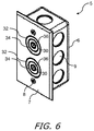
- FIG. 6 a perspective view of two of the female sections 20 of the safety power connector 10 are shown in a standard electrical box 6 . It is anticipated that the standard electrical box 6 is mounted in a wall of a building and power is connected through one or more knockouts 9 (or any other power feed-through as known in the industry). In this, there are two female sections 20 , the contacts 32 / 34 / 36 of each extend out of the faceplate 7 . The faceplate is held to the standard electrical box 6 by two screws 8 .
- FIG. 7 a plan view of two of the female sections of the safety power connector 10 .
- the two female sections of the safety power connector are mounted to a plate 41 that shields internal components. It is anticipated that the female sections of the safety power connector 10 mount within a standard electrical box 6 that is mounted in a wall of a building and power is connected through, for example, one or more knockouts 9 (see FIG. 6 ). In this, there are two female sections 20 , the contacts 32 / 34 / 36 of each female section 20 are supported by the plate 41 .
- FIG. 8 illustrates a perspective view of the two female sections 20 (occluded in FIG. 8 ) of the safety power connector 10 , one having a male section 40 of the safety power connector 10 and the other having a male section to standard outlet converter 81 .
- the male section to standard outlet converter 81 is an example of a outlet converter 81 the connects legacy electrical devices (e.g. having two or three prong plugs as known in the industry) to the female sections 20 of the safety power connector 10 .
- the male section to standard outlet converter 81 has a standard three-prong receptacle 82 for connecting legacy electrical devices, though any type of receptacle is anticipated.
- FIGS. 9, 10, and 11 views of an exemplary embodiment of the male section 40 of the safety power connector 10 .
- the mating ground contact 42 of the male section 40 is connected to a ground interconnect 42 A that connects to a ground wire (not shown e.g., by soldering or a screw terminal).
- the mating neutral contact 44 of the male section 40 is connected to a neutral interconnect 44 A that connects to a neutral wire (not shown e.g., by soldering or a screw terminal).
- the protrusion 50 is shown emanating from a central location and also serves as the mating hot contact 46 of the male section 40 and connects to a hot wire (not shown e.g., by soldering or a screw terminal). Note that there is no specific location required for the protrusion 50 , only that the protrusion 50 mate up with the receptacle 30 when the male section 40 mates with the female section 20 .
- the male section 40 of the safety power connector 10 has a cap portion 40 A having an opening 40 C for accepting a power cable (not shown) that is often tied in a knot within the cap portion 40 A for strain relief and attached to the ground interconnect 42 A, the neutral interconnect 44 A, and to the protrusion 50 /mating hot contact 46 .
- the two magnets 41 A/ 41 B there are two magnets 41 A/ 41 B for sufficient magnetic strength.
- a magnetic shield 40 B that encapsulates the magnetic field of the two magnets 41 A/ 41 B so that the magnetic field does not falsely enable an adjacent female sections 20 of the safety power connector 10 .
- the hot guide 49 maintains the position of the protrusion 50 and insulates the protrusion 50 from the mating neutral contact 44 .
- FIGS. 12, 13, 14, and 15 views of an exemplary male section to standard outlet converter 81 are shown.
- a standard three-prong receptacle 82 At the top of the male section to standard outlet converter 81 is a standard three-prong receptacle 82 , though any known receptacle is anticipated.
- a metal shield 84 encloses the standard three-prong receptacle 82 .
- a single magnet 86 is included (for closing the magnetic switch of the female section 20 ).
- the mating ground contact 42 of the male section 40 is connected to the standard three-prong receptacle 82 through the metal shield 84 .
- the mating neutral contact 44 of the male section 40 is connected to a neutral interconnect 44 A that connects to a neutral wire of the standard three-prong receptacle 82 .
- the protrusion 50 is shown emanating from a central location and also serves as the mating hot contact 46 of the male section 40 and connects to the hot terminal of the standard three-prong receptacle 82 .
- An insulator 85 maintains electrical separation of the neutral interconnect 44 A and protrusion 50 .
- a cover 87 insulates and provides protection to the male section to standard outlet converter 81 .
Landscapes
- Details Of Connecting Devices For Male And Female Coupling (AREA)
Abstract
Description
Claims (20)
Priority Applications (2)
| Application Number | Priority Date | Filing Date | Title |
|---|---|---|---|
| US16/502,167 US10615548B2 (en) | 2018-07-06 | 2019-07-03 | Safety power connector |
| US16/798,415 US20200194942A1 (en) | 2018-07-06 | 2020-02-23 | Safety Power Connector |
Applications Claiming Priority (2)
| Application Number | Priority Date | Filing Date | Title |
|---|---|---|---|
| US201862694726P | 2018-07-06 | 2018-07-06 | |
| US16/502,167 US10615548B2 (en) | 2018-07-06 | 2019-07-03 | Safety power connector |
Related Child Applications (1)
| Application Number | Title | Priority Date | Filing Date |
|---|---|---|---|
| US16/798,415 Continuation-In-Part US20200194942A1 (en) | 2018-07-06 | 2020-02-23 | Safety Power Connector |
Publications (2)
| Publication Number | Publication Date |
|---|---|
| US20200014154A1 US20200014154A1 (en) | 2020-01-09 |
| US10615548B2 true US10615548B2 (en) | 2020-04-07 |
Family
ID=69060002
Family Applications (1)
| Application Number | Title | Priority Date | Filing Date |
|---|---|---|---|
| US16/502,167 Expired - Fee Related US10615548B2 (en) | 2018-07-06 | 2019-07-03 | Safety power connector |
Country Status (3)
| Country | Link |
|---|---|
| US (1) | US10615548B2 (en) |
| CN (1) | CN112352356A (en) |
| WO (1) | WO2020010174A1 (en) |
Families Citing this family (1)
| Publication number | Priority date | Publication date | Assignee | Title |
|---|---|---|---|---|
| GB2632667A (en) * | 2023-08-16 | 2025-02-19 | Aflalo Amit | Male power connector for bidirectional AC power |
Citations (10)
| Publication number | Priority date | Publication date | Assignee | Title |
|---|---|---|---|---|
| US6183264B1 (en) * | 1999-07-19 | 2001-02-06 | HARSáNYI EDUARDO G. | Safety receptacle for electrical outlets |
| US20070149013A1 (en) * | 2005-12-22 | 2007-06-28 | Bryant Eastham | Electrical outlets and plugs with local power enabling and disabling |
| US20110117758A1 (en) | 2009-11-13 | 2011-05-19 | Fujitsu Component Limited | A connector unit with a male connector having a control terminal with a switch |
| US20110148650A1 (en) * | 2009-12-21 | 2011-06-23 | Whirlpool Corporation | Mechanical Proximity Sensor Enabled Electromagnetic Service Connector System |
| US20120171882A1 (en) | 2011-01-04 | 2012-07-05 | Fujitsu Component Limited | Connector unit |
| US20130337673A1 (en) | 2012-04-30 | 2013-12-19 | Club Car, Llc | Power connection system |
| US20140162468A1 (en) | 2011-04-27 | 2014-06-12 | Autoconnector Co., Ltd. | Structure of electromagnetic electrical connection device |
| US20150325953A1 (en) | 2014-05-07 | 2015-11-12 | Microsoft Technology Licensing, Llc | Electronic connector |
| US20160336695A1 (en) | 2012-04-30 | 2016-11-17 | Arash Janfada | Magnetically actuated ac power connector |
| US10069250B2 (en) * | 2015-06-15 | 2018-09-04 | Olympus Corporation | Receptacle connector |
Family Cites Families (15)
| Publication number | Priority date | Publication date | Assignee | Title |
|---|---|---|---|---|
| FR2652954B2 (en) * | 1989-09-26 | 1994-07-13 | El Marry Sagr Majed | ELECTRICAL SAFETY SOCKET SYSTEM. |
| CN201289925Y (en) * | 2008-08-25 | 2009-08-12 | 胡志荣 | Matching electric shock resistance power socket |
| CN201444510U (en) * | 2009-06-12 | 2010-04-28 | 孙向鹏 | A split plug |
| JP5575504B2 (en) * | 2010-02-19 | 2014-08-20 | 富士通コンポーネント株式会社 | Connector device, power supply side connector, and power supply unit |
| CN201608374U (en) * | 2010-03-24 | 2010-10-13 | 宁振江 | Magnetic electric connector |
| CN102386531A (en) * | 2011-12-02 | 2012-03-21 | 河南省电力公司周口供电公司 | Anti-shock plug and socket |
| CN102832515A (en) * | 2012-09-07 | 2012-12-19 | 广州遨控电子科技有限公司 | Circuit structure of magnetic control type safety socket with function of preventing electric shock |
| CN203466388U (en) * | 2013-09-23 | 2014-03-05 | 金永革 | Explosion-proof electric connection device |
| TWI691124B (en) * | 2015-03-20 | 2020-04-11 | 京鼎精密科技股份有限公司 | Magnetic electrical connector and plug of same |
| CN204668528U (en) * | 2015-06-25 | 2015-09-23 | 孙利元 | Safety socket outlet and plug thereof |
| FR3038781B1 (en) * | 2015-07-10 | 2017-07-28 | Gulplug | ELECTRICAL SOCKET ASSEMBLY WITH ELECTRIC DISCONNECT SOLUTION |
| CN204885694U (en) * | 2015-09-06 | 2015-12-16 | 卓玉兰 | A safety control device for socket plug or adapter |
| CN105591250A (en) * | 2016-02-29 | 2016-05-18 | 绍兴文理学院 | Safe socket |
| CN206163784U (en) * | 2016-11-24 | 2017-05-10 | 周利明 | Outlet and plug |
| CN108173035A (en) * | 2017-12-01 | 2018-06-15 | 刘柳媛 | Plug and socket |
-
2019
- 2019-07-03 WO PCT/US2019/040455 patent/WO2020010174A1/en not_active Ceased
- 2019-07-03 CN CN201980045251.2A patent/CN112352356A/en active Pending
- 2019-07-03 US US16/502,167 patent/US10615548B2/en not_active Expired - Fee Related
Patent Citations (11)
| Publication number | Priority date | Publication date | Assignee | Title |
|---|---|---|---|---|
| US6183264B1 (en) * | 1999-07-19 | 2001-02-06 | HARSáNYI EDUARDO G. | Safety receptacle for electrical outlets |
| US20070149013A1 (en) * | 2005-12-22 | 2007-06-28 | Bryant Eastham | Electrical outlets and plugs with local power enabling and disabling |
| US20110117758A1 (en) | 2009-11-13 | 2011-05-19 | Fujitsu Component Limited | A connector unit with a male connector having a control terminal with a switch |
| US20110148650A1 (en) * | 2009-12-21 | 2011-06-23 | Whirlpool Corporation | Mechanical Proximity Sensor Enabled Electromagnetic Service Connector System |
| US20120171882A1 (en) | 2011-01-04 | 2012-07-05 | Fujitsu Component Limited | Connector unit |
| US20140162468A1 (en) | 2011-04-27 | 2014-06-12 | Autoconnector Co., Ltd. | Structure of electromagnetic electrical connection device |
| US20130337673A1 (en) | 2012-04-30 | 2013-12-19 | Club Car, Llc | Power connection system |
| US9190782B2 (en) * | 2012-04-30 | 2015-11-17 | Club Car, Llc | Power connection system |
| US20160336695A1 (en) | 2012-04-30 | 2016-11-17 | Arash Janfada | Magnetically actuated ac power connector |
| US20150325953A1 (en) | 2014-05-07 | 2015-11-12 | Microsoft Technology Licensing, Llc | Electronic connector |
| US10069250B2 (en) * | 2015-06-15 | 2018-09-04 | Olympus Corporation | Receptacle connector |
Also Published As
| Publication number | Publication date |
|---|---|
| US20200014154A1 (en) | 2020-01-09 |
| WO2020010174A1 (en) | 2020-01-09 |
| CN112352356A (en) | 2021-02-09 |
Similar Documents
| Publication | Publication Date | Title |
|---|---|---|
| US7009473B2 (en) | Ground-fault circuit interrupter with reverse wiring protection | |
| KR101171070B1 (en) | Electromagnetism Electricity Connection Device | |
| US9660378B2 (en) | Magnetic electrical connector | |
| US3816679A (en) | Magnetically operated electrical connector | |
| US8366463B2 (en) | Safety structure for electric receptacles and power strips | |
| US20200194942A1 (en) | Safety Power Connector | |
| US10644461B2 (en) | Modified electrical devices | |
| US10312640B2 (en) | Magnetically activated power socket and plug combination | |
| SK132397A3 (en) | Electromechanical connection device | |
| CA2968873A1 (en) | Electrical devices with longitudinal electrical conductor entries | |
| US10468818B2 (en) | Magnetically activated power socket and plug combination | |
| US20200203895A1 (en) | Adapter assembly for contactless transfer of electrical power | |
| US10615548B2 (en) | Safety power connector | |
| US20030124893A1 (en) | Electrical safety outlet | |
| TWI691124B (en) | Magnetic electrical connector and plug of same | |
| US20030085108A1 (en) | Electrical safety outlet which can prevent electric shocks from accidental contacts | |
| CA2562758A1 (en) | Method and apparatus for preventing electric shocking | |
| CN106159549B (en) | Magnetic electric connector and its connector | |
| US20130303024A1 (en) | Safety Electrical Interconnect | |
| CN105655805A (en) | Socket for night use | |
| US7465174B1 (en) | Coupling for connecting and disconnecting a plug and a socket | |
| US20220360025A1 (en) | Cable switch with usb charger | |
| EP0329974B1 (en) | Electrical safety socket | |
| US20120252241A1 (en) | Shock-proof electric outlet | |
| CN106329221B (en) | Safety plug component |
Legal Events
| Date | Code | Title | Description |
|---|---|---|---|
| AS | Assignment |
Owner name: PINK, STEVEN, FLORIDA Free format text: ASSIGNMENT OF ASSIGNORS INTEREST;ASSIGNORS:ORAVECZ, ANDREW W.;HEAD, JOHN, III;SPEHR, RICHARD PAUL;AND OTHERS;SIGNING DATES FROM 20180508 TO 20190627;REEL/FRAME:049660/0808 |
|
| FEPP | Fee payment procedure |
Free format text: ENTITY STATUS SET TO UNDISCOUNTED (ORIGINAL EVENT CODE: BIG.); ENTITY STATUS OF PATENT OWNER: MICROENTITY |
|
| FEPP | Fee payment procedure |
Free format text: ENTITY STATUS SET TO MICRO (ORIGINAL EVENT CODE: MICR); ENTITY STATUS OF PATENT OWNER: MICROENTITY |
|
| STPP | Information on status: patent application and granting procedure in general |
Free format text: NOTICE OF ALLOWANCE MAILED -- APPLICATION RECEIVED IN OFFICE OF PUBLICATIONS |
|
| ZAAA | Notice of allowance and fees due |
Free format text: ORIGINAL CODE: NOA |
|
| ZAAB | Notice of allowance mailed |
Free format text: ORIGINAL CODE: MN/=. |
|
| STPP | Information on status: patent application and granting procedure in general |
Free format text: PUBLICATIONS -- ISSUE FEE PAYMENT RECEIVED |
|
| STCF | Information on status: patent grant |
Free format text: PATENTED CASE |
|
| FEPP | Fee payment procedure |
Free format text: MAINTENANCE FEE REMINDER MAILED (ORIGINAL EVENT CODE: REM.); ENTITY STATUS OF PATENT OWNER: MICROENTITY |
|
| LAPS | Lapse for failure to pay maintenance fees |
Free format text: PATENT EXPIRED FOR FAILURE TO PAY MAINTENANCE FEES (ORIGINAL EVENT CODE: EXP.); ENTITY STATUS OF PATENT OWNER: MICROENTITY |
|
| STCH | Information on status: patent discontinuation |
Free format text: PATENT EXPIRED DUE TO NONPAYMENT OF MAINTENANCE FEES UNDER 37 CFR 1.362 |
|
| FP | Lapsed due to failure to pay maintenance fee |
Effective date: 20240407 |