US1061451A - Drill-supporting mechanism. - Google Patents
Drill-supporting mechanism. Download PDFInfo
- Publication number
- US1061451A US1061451A US68941212A US1912689412A US1061451A US 1061451 A US1061451 A US 1061451A US 68941212 A US68941212 A US 68941212A US 1912689412 A US1912689412 A US 1912689412A US 1061451 A US1061451 A US 1061451A
- Authority
- US
- United States
- Prior art keywords
- drill
- piston
- cylinders
- bed plate
- groove
- Prior art date
- Legal status (The legal status is an assumption and is not a legal conclusion. Google has not performed a legal analysis and makes no representation as to the accuracy of the status listed.)
- Expired - Lifetime
Links
- 108091006146 Channels Proteins 0.000 description 8
- 239000012530 fluid Substances 0.000 description 6
- 230000015572 biosynthetic process Effects 0.000 description 1
- 238000005266 casting Methods 0.000 description 1
- 238000010276 construction Methods 0.000 description 1
- 230000008878 coupling Effects 0.000 description 1
- 238000010168 coupling process Methods 0.000 description 1
- 238000005859 coupling reaction Methods 0.000 description 1
- 230000000694 effects Effects 0.000 description 1
- 239000007787 solid Substances 0.000 description 1
- 230000005641 tunneling Effects 0.000 description 1
Images
Classifications
-
- B—PERFORMING OPERATIONS; TRANSPORTING
- B25—HAND TOOLS; PORTABLE POWER-DRIVEN TOOLS; MANIPULATORS
- B25D—PERCUSSIVE TOOLS
- B25D9/00—Portable percussive tools with fluid-pressure drive, i.e. driven directly by fluids, e.g. having several percussive tool bits operated simultaneously
- B25D9/06—Means for driving the impulse member
- B25D9/08—Means for driving the impulse member comprising a built-in air compressor, i.e. the tool being driven by air pressure
Definitions
- This invention relates to drill supporting mechanism and the object of the invention is a compact and etlicient drill carrying and operating mechanism in which a gang of drills is operated without valves or valve gear. 7
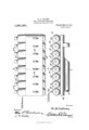
- Figure l is a top plan View
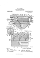
- Fig. 2 is a vertical transverse section on the line 22 of Fig. 1
- Fig. 3 is a rear elevation of the form of construction shown in Figs. 1 and 2
- Figs. 4- and 5 are sectional details taken on the lines ir-" f and f-5 respectively of Fig. 2.
- 11 the bed plate of the drill carrying body which is provided with a longitudinal passage 2 for compressed air or steam, the term pneumatic used hereinafter having reference broadly to pressure fluid whether steam, air or other gaseous pressure medium.
- the outer end of the passage 2 is provided with a coupling 3 by which it is connected to a suit able source of pressure fluid supply, usually a chamber Within the frame or the rotary head of the tunneling machine upon which the drill is used.
- This passage 2 extends preferably throughout one half of the length of the bed plate and is connected at its end by a short vertical channel 1 with an air chamber 5 extending longitudinally of the bed plate.
- the upper face of the bed plate is incut to form a dove tail groove 6 having upwardly converging walls 7.
- the bottom of this groove at 8 is ground smooth to form a tight joint with the bottom surface of the dove tail tongue 10 formed on the lower portion of the drill body.
- the tongue 10 is adapted to be slipped lengthwise into Specification of Letters Patent.
- the dove tail groove (3, the meeting faces 8 and 9 forming an air tight joint when the set screw 1.]. is screwed home forcing the beveled plug 12 against the inclined side of the tongue and thereby forcing the drill body in the opposite direction against the inclined wall 7 and cooperating therewith to seat the tongue 10 firmly upon the bottom of the groove 6.
- the drill body 13 is preferably made of a solid casting bored out transversely at intervals to form the drill cylinders 14: into which cylinder heads 15 are screw threaded at the rear and provided with angular recesses 16 for the application of a wrench or the like.
- the upper wall of the drill, body is provided at intervals with exhaust ports 17 leading from each of the cylinders just to the rear of a medial line, the exhaust ports being preferably provided with deflector hoods 18.
- Inlet channels 19 lead from the air chamber 5 to each of the cylinders 1 1 entering the same at the inlets 20 at the forward end thereof.
- the transverse bore through the cylinder body is slightly reduced in size from the forward end of the cylinder to the face of the cylinder body forming a cylindrical guide 21 within which the piston extension 22 travels.
- This extension 22 is cored out at 23 to receive the shank of the drill or other. tool 2 1 and upon the opposite sides of this cavity 23 are provided longitudinal grooves 25 within which the studs 26 carried by the tool shank engage to prevent relative rotary IllOVCIIlQlli'.
- the piston extension 22 is further reduced and threaded at 27 to receive the clamping collar 28 by which the drill shank secured .in place, the collar 28 hearing upon an interposed washer 29 which in turn bears against the stud 26.
- the piston proper is composed of a rear portion 30 of a diameter to snugly fit within the cylinder and of a forward portion 3T of slightly reduced diameter to provide an an nular interspaee 32 between the same and the cylinder walls which inter-space is bounded at the rear by the annular shoulder 83.
- the forward end of the piston is provided with an annular groove 34; bounded on the rear by the wall and in front by the wall 36.
- the piston is further provided with a plurality of longitrulinal bores 37 extending from the grooves 341 through the body of the piston to the rear face of the same at 38.
- the head of the piston is formed with one or more lugs 30 which work in grooves 14; formed in the cylinder, whereby the piston is prevented from rotating in the drill cylinder and is limited to a reciprocating movement therein.
- a bed plate having an air passage formed therein and provided in its upper face With 21 dove tail groove, a drill carrier fitted within the said groove, a plurality of cylinders formed as an integral part of and supported by the carrier, the several cylinders each having an inlet port and an exhaust port, the upper face-of the bed plate is provided with a feed chamber, means to clamp the carrier upon the bed plate to form an air-tight joint, an air channel leading from the air passage to the feed chamber, branched channels leading from the chamber to the inlet ports of the cylinders,
- the combination with a bed plate provided in its upper face with a dove-tail groove, an air passage formed within said bed plate, a drill carrier slidably mounted Within said dovetail groove, a plurality of cylinders supported by the drill carrier, theseveral cylinders each having an inlet and exhaust port, a feed chamber formed within the upper face of the bed plate and communicating with said air passage, the said bed plate having a plurality of, diagonally extending channels communicating with said feed chamber and the several inlet ports of the cylinders, and a tool bearing piston in each of said cylinders.
- a bed plate having an air passage formed therein and provided in its upper face with a dove tail groove, a drill carrier, a tongue formed integrally with said drill carrier and slidably mounted within said groove, a beveled plug adjustably mounted within said bed plate and adapted to engage said tongue, a plurality of cylinders supported by the carrier, the several cylinders each having an inlet port and an exhaust port, means of communication between said air passage and the inlet ports of the several cylinders, and a tool bearing piston in each of said cylinders.
- a bed plate having a longitudinally extending air passage formed therein and terminating adjacent the central portion thereof, the upper face of said bed plate having a dove tail groove, a drill carrier slidably mounted Within said dovetail groove, a plurality of cylinders supported by said carrier, the several cylinders each having an inlet port and an exhaust port, the upper face of said bed plate having a feed chamber formed therein extending parallel with said dove tail groove, a channel leading from said air passage and communicating with said chamber, branched chan nels leading from said chamber to the inlet ports of the several cylinders, and a tool bearing piston in each of said cylinders.
Landscapes
- Physics & Mathematics (AREA)
- Fluid Mechanics (AREA)
- Engineering & Computer Science (AREA)
- Mechanical Engineering (AREA)
- Perforating, Stamping-Out Or Severing By Means Other Than Cutting (AREA)
Description
W. R. COLLINS.
DRILL SUPPORTING MECHANISM.
APPLICATION FILED APB.B, 1912.
1,061,451 Patented May 13, 1913.
2 8HEETS-SHEET 1.
Illlll El H H glwvuewtov wi/bnzoaeo 7 71/8 CDLUMEIlA PLANOBRAPII :0 WASHINGTON u c W. R. COLLINS.
DRILL SUPPORTING MECHANISM.
AAAAAAAAAAAAAAAAAAAAAAAAA 2.
1,061,451 Patented May 13, 1913.
2 SHEETS-SHEET 2- WILLIAM R. COLLINS, OF CHICAGO, ILLINOIS.
DRILL-SUPPORTING MECHANISM.
Application filed April 8, 1912.
To all whom it may concern Be it known that I, lViLLiAM R. COLLINS, a citizen of the United States, residing at Chicago, in the county of Cool: and State of Illinois, have invented certain new and use ful Improvements in Drill Supporting Mechanism, of which the following is a specification, reference being had to the ac companying drawings.
This invention relates to drill supporting mechanism and the object of the invention is a compact and etlicient drill carrying and operating mechanism in which a gang of drills is operated without valves or valve gear. 7
The invention as hereinafter particularly claimed will be readily understood from the following detail description thereof taken in connection with the accompanying illustrative drawings wherein is shown a preferred and also a modified embodiment of the invention.
In these drawingsFigure l is a top plan View; Fig. 2 is a vertical transverse section on the line 22 of Fig. 1; Fig. 3 is a rear elevation of the form of construction shown in Figs. 1 and 2, Figs. 4- and 5 are sectional details taken on the lines ir-" f and f-5 respectively of Fig. 2.
Referring more particularly to the drawings, wherein like reference numerals designate corresponding parts throughout, 11s the bed plate of the drill carrying body which is provided with a longitudinal passage 2 for compressed air or steam, the term pneumatic used hereinafter having reference broadly to pressure fluid whether steam, air or other gaseous pressure medium. The outer end of the passage 2 is provided with a coupling 3 by which it is connected to a suit able source of pressure fluid supply, usually a chamber Within the frame or the rotary head of the tunneling machine upon which the drill is used. This passage 2 extends preferably throughout one half of the length of the bed plate and is connected at its end by a short vertical channel 1 with an air chamber 5 extending longitudinally of the bed plate. The upper face of the bed plate is incut to form a dove tail groove 6 having upwardly converging walls 7. The bottom of this groove at 8 is ground smooth to form a tight joint with the bottom surface of the dove tail tongue 10 formed on the lower portion of the drill body. The tongue 10 is adapted to be slipped lengthwise into Specification of Letters Patent.
Patented May 13,1913.
Serial No. 689,412.
the dove tail groove (3, the meeting faces 8 and 9 forming an air tight joint when the set screw 1.]. is screwed home forcing the beveled plug 12 against the inclined side of the tongue and thereby forcing the drill body in the opposite direction against the inclined wall 7 and cooperating therewith to seat the tongue 10 firmly upon the bottom of the groove 6.
The drill body 13 is preferably made of a solid casting bored out transversely at intervals to form the drill cylinders 14: into which cylinder heads 15 are screw threaded at the rear and provided with angular recesses 16 for the application of a wrench or the like. The upper wall of the drill, body is provided at intervals with exhaust ports 17 leading from each of the cylinders just to the rear of a medial line, the exhaust ports being preferably provided with deflector hoods 18. Inlet channels 19 lead from the air chamber 5 to each of the cylinders 1 1 entering the same at the inlets 20 at the forward end thereof. The transverse bore through the cylinder body is slightly reduced in size from the forward end of the cylinder to the face of the cylinder body forming a cylindrical guide 21 within which the piston extension 22 travels. This extension 22 is cored out at 23 to receive the shank of the drill or other. tool 2 1 and upon the opposite sides of this cavity 23 are provided longitudinal grooves 25 within which the studs 26 carried by the tool shank engage to prevent relative rotary IllOVCIIlQlli'. The piston extension 22 is further reduced and threaded at 27 to receive the clamping collar 28 by which the drill shank secured .in place, the collar 28 hearing upon an interposed washer 29 which in turn bears against the stud 26.
The piston proper is composed of a rear portion 30 of a diameter to snugly fit within the cylinder and of a forward portion 3T of slightly reduced diameter to provide an an nular interspaee 32 between the same and the cylinder walls which inter-space is bounded at the rear by the annular shoulder 83. The forward end of the piston is provided with an annular groove 34; bounded on the rear by the wall and in front by the wall 36. The piston is further provided with a plurality of longitrulinal bores 37 extending from the grooves 341 through the body of the piston to the rear face of the same at 38.
The location of the groove, of the inlet port and of the exhaust port and the conshoulder 33.
formation of the piston are such that when the piston is in its rearmost position the shoulder 33 will coincide substantially with the front wall of the exhaust port 17 and the groove 34 will register substantially with the inlet port 20. It will thus be seen that, pressure fluid being supplied through the passage 2 and from it to the chamber 5, such pressure fluid will be admitted through the channels 19 and the inlet ports 20 to the groove 34 and thence by means of the bores 37 to the rear face of the piston driving the same forward by reason of the excess area exposed to the pressure fluid at the rear of the pistonv over that exposed at the As soon as the piston has reached the position wherein the exhaust port is brought into communication with the space at the rear of the piston and the pressure relieved from the piston at that end, the pressure on the shoulder 33 will return the piston thus resulting in a reciproeatory movement of the piston without the use of valves and also doing away with the necessity of cushioning devices, the cushioning effect being obtained from the pressure fluid trapped upon the return stroke between the rear face of the piston and the cylinder head.
The number of cylinders, pistons and tools will depend altogether upon the requirements of the service there being one or many as circumstances may necessitate, the operation being the same under all conditions.
Preferably, the head of the piston is formed with one or more lugs 30 which work in grooves 14; formed in the cylinder, whereby the piston is prevented from rotating in the drill cylinder and is limited to a reciprocating movement therein.
Having thus described the invention, what is claimed is:
1. In a device of the character described, a bed plate having an air passage formed therein and provided in its upper face With 21 dove tail groove, a drill carrier fitted within the said groove, a plurality of cylinders formed as an integral part of and supported by the carrier, the several cylinders each having an inlet port and an exhaust port, the upper face-of the bed plate is provided with a feed chamber, means to clamp the carrier upon the bed plate to form an air-tight joint, an air channel leading from the air passage to the feed chamber, branched channels leading from the chamber to the inlet ports of the cylinders,
and a tool bearing piston in each of the cylinders.
2. In a device of the character described, the combination with a bed plate provided in its upper face with a dove-tail groove, an air passage formed within said bed plate, a drill carrier slidably mounted Within said dovetail groove, a plurality of cylinders supported by the drill carrier, theseveral cylinders each having an inlet and exhaust port, a feed chamber formed within the upper face of the bed plate and communicating with said air passage, the said bed plate having a plurality of, diagonally extending channels communicating with said feed chamber and the several inlet ports of the cylinders, and a tool bearing piston in each of said cylinders.
3. In a device of the character described, a bed plate having an air passage formed therein and provided in its upper face with a dove tail groove, a drill carrier, a tongue formed integrally with said drill carrier and slidably mounted within said groove, a beveled plug adjustably mounted within said bed plate and adapted to engage said tongue, a plurality of cylinders supported by the carrier, the several cylinders each having an inlet port and an exhaust port, means of communication between said air passage and the inlet ports of the several cylinders, and a tool bearing piston in each of said cylinders.
4. In a device of the character described, the combination of a bed plate having a longitudinally extending air passage formed therein and terminating adjacent the central portion thereof, the upper face of said bed plate having a dove tail groove, a drill carrier slidably mounted Within said dovetail groove, a plurality of cylinders supported by said carrier, the several cylinders each having an inlet port and an exhaust port, the upper face of said bed plate having a feed chamber formed therein extending parallel with said dove tail groove, a channel leading from said air passage and communicating with said chamber, branched chan nels leading from said chamber to the inlet ports of the several cylinders, and a tool bearing piston in each of said cylinders.
In testimony whereof I hereunto affix my signature in the presence of two witnesses.
WILLIAM R. COLLINS.
Copies of this patent may be obtained for five cents each, by addressing the Commissioner of Patents,
Washington, D. C.
Priority Applications (1)
| Application Number | Priority Date | Filing Date | Title |
|---|---|---|---|
| US68941212A US1061451A (en) | 1912-04-08 | 1912-04-08 | Drill-supporting mechanism. |
Applications Claiming Priority (1)
| Application Number | Priority Date | Filing Date | Title |
|---|---|---|---|
| US68941212A US1061451A (en) | 1912-04-08 | 1912-04-08 | Drill-supporting mechanism. |
Publications (1)
| Publication Number | Publication Date |
|---|---|
| US1061451A true US1061451A (en) | 1913-05-13 |
Family
ID=3129697
Family Applications (1)
| Application Number | Title | Priority Date | Filing Date |
|---|---|---|---|
| US68941212A Expired - Lifetime US1061451A (en) | 1912-04-08 | 1912-04-08 | Drill-supporting mechanism. |
Country Status (1)
| Country | Link |
|---|---|
| US (1) | US1061451A (en) |
-
1912
- 1912-04-08 US US68941212A patent/US1061451A/en not_active Expired - Lifetime
Similar Documents
| Publication | Publication Date | Title |
|---|---|---|
| US1518124A (en) | Apparatus for drilling holes | |
| US1658330A (en) | Drilling machine | |
| US1233477A (en) | Drilling-machine. | |
| US745900A (en) | Pneumatically-operated percussive tool. | |
| US1982656A (en) | Drilling machine | |
| US700081A (en) | Impact-tool. | |
| US1408176A (en) | Pneumatic drill | |
| US964416A (en) | Drill-chuck. | |
| US1150592A (en) | Pressure-fed tool. | |
| US2001718A (en) | Rock drilling motor | |
| US2087583A (en) | Throttle valve for pneumatic tools | |
| US967239A (en) | Fluid-operated rock-drill. | |
| US1563802A (en) | Water-tube connection | |
| US1314288A (en) | Daniel s | |
| US1424156A (en) | Fluid-operated motor | |
| US1042359A (en) | Rock-drill. | |
| US1868670A (en) | Back head construction for rock drills | |
| US1326825A (en) | andersbon | |
| US364081A (en) | Pneumatic drilling-tool | |
| US841069A (en) | Pneumatic drill. | |
| US1792881A (en) | Blowing device | |
| US233020A (en) | Eighths of his eight to ueiah k | |
| US619147A (en) | Rock-drilling machine | |
| US1391628A (en) | Percussive-tool | |
| US1236703A (en) | Pressure-fluid tool. |