US10612557B2 - Nose cone attachment for turbofan engine - Google Patents
Nose cone attachment for turbofan engine Download PDFInfo
- Publication number
- US10612557B2 US10612557B2 US15/211,756 US201615211756A US10612557B2 US 10612557 B2 US10612557 B2 US 10612557B2 US 201615211756 A US201615211756 A US 201615211756A US 10612557 B2 US10612557 B2 US 10612557B2
- Authority
- US
- United States
- Prior art keywords
- nose cone
- hub
- blisk
- connector
- balancing
- Prior art date
- Legal status (The legal status is an assumption and is not a legal conclusion. Google has not performed a legal analysis and makes no representation as to the accuracy of the status listed.)
- Active, expires
Links
- 241000237503 Pectinidae Species 0.000 claims description 15
- 235000020637 scallop Nutrition 0.000 claims description 15
- 238000000034 method Methods 0.000 claims description 13
- 230000007246 mechanism Effects 0.000 claims description 11
- 230000008878 coupling Effects 0.000 claims description 8
- 238000010168 coupling process Methods 0.000 claims description 8
- 238000005859 coupling reaction Methods 0.000 claims description 8
- 230000006835 compression Effects 0.000 claims description 6
- 238000007906 compression Methods 0.000 claims description 6
- 230000002452 interceptive effect Effects 0.000 claims 2
- 238000013461 design Methods 0.000 description 17
- 238000004519 manufacturing process Methods 0.000 description 8
- 229910052782 aluminium Inorganic materials 0.000 description 6
- XAGFODPZIPBFFR-UHFFFAOYSA-N aluminium Chemical compound [Al] XAGFODPZIPBFFR-UHFFFAOYSA-N 0.000 description 6
- 239000002131 composite material Substances 0.000 description 5
- 230000007423 decrease Effects 0.000 description 5
- 239000000463 material Substances 0.000 description 5
- 230000003247 decreasing effect Effects 0.000 description 4
- 238000005242 forging Methods 0.000 description 4
- 238000012986 modification Methods 0.000 description 4
- 230000004048 modification Effects 0.000 description 4
- 239000000446 fuel Substances 0.000 description 2
- 238000010348 incorporation Methods 0.000 description 2
- 238000003754 machining Methods 0.000 description 2
- 229910052751 metal Inorganic materials 0.000 description 2
- 239000002184 metal Substances 0.000 description 2
- 238000004806 packaging method and process Methods 0.000 description 2
- 239000002861 polymer material Substances 0.000 description 2
- 230000009467 reduction Effects 0.000 description 2
- 230000002829 reductive effect Effects 0.000 description 2
- 239000013585 weight reducing agent Substances 0.000 description 2
- 230000006978 adaptation Effects 0.000 description 1
- 230000000712 assembly Effects 0.000 description 1
- 238000000429 assembly Methods 0.000 description 1
- 238000004891 communication Methods 0.000 description 1
- 230000000295 complement effect Effects 0.000 description 1
- 230000001627 detrimental effect Effects 0.000 description 1
- 238000011161 development Methods 0.000 description 1
- 230000009977 dual effect Effects 0.000 description 1
- 238000002347 injection Methods 0.000 description 1
- 239000007924 injection Substances 0.000 description 1
- 230000000670 limiting effect Effects 0.000 description 1
- 238000005457 optimization Methods 0.000 description 1
- 230000036961 partial effect Effects 0.000 description 1
- 229920000642 polymer Polymers 0.000 description 1
- 238000011160 research Methods 0.000 description 1
- 230000000717 retained effect Effects 0.000 description 1
Images


Classifications
-
- F—MECHANICAL ENGINEERING; LIGHTING; HEATING; WEAPONS; BLASTING
- F04—POSITIVE - DISPLACEMENT MACHINES FOR LIQUIDS; PUMPS FOR LIQUIDS OR ELASTIC FLUIDS
- F04D—NON-POSITIVE-DISPLACEMENT PUMPS
- F04D29/00—Details, component parts, or accessories
- F04D29/26—Rotors specially for elastic fluids
- F04D29/32—Rotors specially for elastic fluids for axial flow pumps
- F04D29/325—Rotors specially for elastic fluids for axial flow pumps for axial flow fans
- F04D29/329—Details of the hub
-
- B—PERFORMING OPERATIONS; TRANSPORTING
- B64—AIRCRAFT; AVIATION; COSMONAUTICS
- B64C—AEROPLANES; HELICOPTERS
- B64C11/00—Propellers, e.g. of ducted type; Features common to propellers and rotors for rotorcraft
- B64C11/02—Hub construction
- B64C11/14—Spinners
-
- F—MECHANICAL ENGINEERING; LIGHTING; HEATING; WEAPONS; BLASTING
- F02—COMBUSTION ENGINES; HOT-GAS OR COMBUSTION-PRODUCT ENGINE PLANTS
- F02C—GAS-TURBINE PLANTS; AIR INTAKES FOR JET-PROPULSION PLANTS; CONTROLLING FUEL SUPPLY IN AIR-BREATHING JET-PROPULSION PLANTS
- F02C7/00—Features, components parts, details or accessories, not provided for in, or of interest apart form groups F02C1/00 - F02C6/00; Air intakes for jet-propulsion plants
- F02C7/04—Air intakes for gas-turbine plants or jet-propulsion plants
-
- F—MECHANICAL ENGINEERING; LIGHTING; HEATING; WEAPONS; BLASTING
- F02—COMBUSTION ENGINES; HOT-GAS OR COMBUSTION-PRODUCT ENGINE PLANTS
- F02K—JET-PROPULSION PLANTS
- F02K3/00—Plants including a gas turbine driving a compressor or a ducted fan
- F02K3/02—Plants including a gas turbine driving a compressor or a ducted fan in which part of the working fluid by-passes the turbine and combustion chamber
- F02K3/04—Plants including a gas turbine driving a compressor or a ducted fan in which part of the working fluid by-passes the turbine and combustion chamber the plant including ducted fans, i.e. fans with high volume, low pressure outputs, for augmenting the jet thrust, e.g. of double-flow type
- F02K3/06—Plants including a gas turbine driving a compressor or a ducted fan in which part of the working fluid by-passes the turbine and combustion chamber the plant including ducted fans, i.e. fans with high volume, low pressure outputs, for augmenting the jet thrust, e.g. of double-flow type with front fan
-
- F—MECHANICAL ENGINEERING; LIGHTING; HEATING; WEAPONS; BLASTING
- F04—POSITIVE - DISPLACEMENT MACHINES FOR LIQUIDS; PUMPS FOR LIQUIDS OR ELASTIC FLUIDS
- F04D—NON-POSITIVE-DISPLACEMENT PUMPS
- F04D29/00—Details, component parts, or accessories
- F04D29/60—Mounting; Assembling; Disassembling
- F04D29/64—Mounting; Assembling; Disassembling of axial pumps
- F04D29/644—Mounting; Assembling; Disassembling of axial pumps especially adapted for elastic fluid pumps
-
- F—MECHANICAL ENGINEERING; LIGHTING; HEATING; WEAPONS; BLASTING
- F05—INDEXING SCHEMES RELATING TO ENGINES OR PUMPS IN VARIOUS SUBCLASSES OF CLASSES F01-F04
- F05D—INDEXING SCHEME FOR ASPECTS RELATING TO NON-POSITIVE-DISPLACEMENT MACHINES OR ENGINES, GAS-TURBINES OR JET-PROPULSION PLANTS
- F05D2220/00—Application
- F05D2220/30—Application in turbines
- F05D2220/36—Application in turbines specially adapted for the fan of turbofan engines
-
- F—MECHANICAL ENGINEERING; LIGHTING; HEATING; WEAPONS; BLASTING
- F05—INDEXING SCHEMES RELATING TO ENGINES OR PUMPS IN VARIOUS SUBCLASSES OF CLASSES F01-F04
- F05D—INDEXING SCHEME FOR ASPECTS RELATING TO NON-POSITIVE-DISPLACEMENT MACHINES OR ENGINES, GAS-TURBINES OR JET-PROPULSION PLANTS
- F05D2230/00—Manufacture
- F05D2230/60—Assembly methods
-
- F—MECHANICAL ENGINEERING; LIGHTING; HEATING; WEAPONS; BLASTING
- F05—INDEXING SCHEMES RELATING TO ENGINES OR PUMPS IN VARIOUS SUBCLASSES OF CLASSES F01-F04
- F05D—INDEXING SCHEME FOR ASPECTS RELATING TO NON-POSITIVE-DISPLACEMENT MACHINES OR ENGINES, GAS-TURBINES OR JET-PROPULSION PLANTS
- F05D2240/00—Components
- F05D2240/10—Stators
- F05D2240/12—Fluid guiding means, e.g. vanes
-
- F—MECHANICAL ENGINEERING; LIGHTING; HEATING; WEAPONS; BLASTING
- F05—INDEXING SCHEMES RELATING TO ENGINES OR PUMPS IN VARIOUS SUBCLASSES OF CLASSES F01-F04
- F05D—INDEXING SCHEME FOR ASPECTS RELATING TO NON-POSITIVE-DISPLACEMENT MACHINES OR ENGINES, GAS-TURBINES OR JET-PROPULSION PLANTS
- F05D2260/00—Function
- F05D2260/30—Retaining components in desired mutual position
-
- Y—GENERAL TAGGING OF NEW TECHNOLOGICAL DEVELOPMENTS; GENERAL TAGGING OF CROSS-SECTIONAL TECHNOLOGIES SPANNING OVER SEVERAL SECTIONS OF THE IPC; TECHNICAL SUBJECTS COVERED BY FORMER USPC CROSS-REFERENCE ART COLLECTIONS [XRACs] AND DIGESTS
- Y02—TECHNOLOGIES OR APPLICATIONS FOR MITIGATION OR ADAPTATION AGAINST CLIMATE CHANGE
- Y02T—CLIMATE CHANGE MITIGATION TECHNOLOGIES RELATED TO TRANSPORTATION
- Y02T50/00—Aeronautics or air transport
- Y02T50/60—Efficient propulsion technologies, e.g. for aircraft
Definitions
- the present subject matter relates to engines, and more particularly, to attaching nose cones to turbofan engines.
- Turbofan engines are frequently employed in aviation. Referring now to the prior art design shown in FIG. 1 a typical turbofan engine 30 is illustrated.
- the turbofan engine 30 includes a case 32 surrounding a turbofan 34 and a number of compressor stages.
- Fan blade(s) 36 are secured to a shaft 38 by way of a rotor disk or hub 40 during normal operation.
- Conventional turbofan engines employ fan blade(s) 36 that are not integral to the rotor disk 40 . Instead, the fan blade(s) 36 are individually joined to the rotor disk 40 by dovetail joints.
- the rotor disk 40 has mounting slots arranged around an exterior surface thereof. During normal operation, the shaft 38 rotates thereby rotating the hub 40 . The hub 40 in turn produces the rotation of the fan blade(s) 36 around the shaft 38 .
- the turbofan engine 30 takes air into the engine at the turbofan 34 stage.
- the turbofan engine 30 directs the air through a number of low pressure, intermediate pressure, and high-pressure compressor and turbine stages before the air is mixed with fuel, combusted, and passed through a number of turbine stages.
- the air eventually exits the engine 30 through an exhaust.
- the various stages, like the turbofan 34 are configured to rotate with the shaft 38 .
- Air is pulled into the engine 30 through a front opening 42 of the engine 30 and into the turbofan 34 stage.
- the turbofan engine 30 may use conventional fan blades 36 that attach to the rotor disk 40 at a dovetail joint, as described above.
- the turbofan engine 30 may instead use an integrally bladed rotor or bladed disk (“blisk”).
- blisk integrally bladed rotor or bladed disk
- FIG. 2 a blisk 48 comprising a single component is depicted. Blisks may be machined from a single piece of metal, forged or cast as one part, or welded together into a single piece.
- fan blades or airfoils 50 are integrally formed to a blisk hub 52 .
- blade platforms 46 provide a secondary surface that has aerodynamic qualities surrounding the hub 40 , which otherwise would have joints, mounting slots, and blade roots 44 exposed to the airflow through the turbofan 34 stage.
- blade platforms 46 are not included, once again because the blisk fan airfoil(s) 50 attach directly to the blisk hub 52 . Therefore, an analogous aerodynamic interior surface for the blisk 48 turbofan design is provided by the outer surface 54 of the blisk hub 52 .
- a nose cone assembly 56 is attached to the hub 40 or blisk hub 52 .
- the nose cone assembly 56 has a generally conical shape.
- the central axis of the nose cone assembly 56 is substantially aligned with the axis of the rotating shaft 38 .
- a conical tip 58 of the nose cone assembly 56 points out and away from the front opening 42 of the turbofan engine 30 .
- the nose cone assembly 56 expands to form a substantially circular base 60 that meets and is secured to the hub 40 or blisk hub 52 typically by a separate mount ring.
- the diameter of the substantially circular base 60 of the nose cone assembly 56 may be more or less large, relative the hub 40 or blisk hub 52 , depending on the particular nose cone assembly design 56 and the manner by which the substantially circular base 60 is attached to the hub 40 or blisk hub 52 . It is an objective of the nose cone assembly 56 to provide an aerodynamic path for air entering the front opening 42 of the turbofan engine 30 .
- the conventional nose cone assembly 56 utilizes an aluminum nose cone mount ring 62 .
- the aluminum nose cone mount ring 62 of the conventional design also serves as a forward blade retainer 74 that secures the blade root 44 within a respective mounting slot.
- the nose cone mount ring 62 includes a securing component 76 such as bolts, screws, or other base end fastener pieces 70 that secure the nose cone mount ring 62 to a hub flange 72 .
- These securing components 76 operate in conjunction with fingers or tangs extending radially inward from the nose cone mount ring 62 to attach to the fan disc hub 40 .
- the fingers or tangs and the securing components 76 operate together to attach to the nose cone assembly 56 .
- a portion of the mount ring 62 radially outside the hub flange 72 acts as the forward blade retainer 74 .
- the securing component(s) 76 used to attach the nose cone mount ring 62 to the hub flange 72 frequently serve the dual purpose of customizing forward balance and/or trim balance. Although the holes or other removal of material that provides space for the securing component(s) 76 may be used to customize forward balance.
- Conventionally an aluminum, composite, or polymer material is used for the nose cone assembly 56 to achieve reduced weight and cost.
- mechanically bolting to a polymer or composite material may cause stresses the selected material is not be capable of withstanding.
- the nose cone assembly 56 for the blisk 48 turbofan may be attached by either a blisk nose cone mount ring or integral blisk attachment fingers 80 .
- FIG. 4 a configuration of the blisk 48 turbofan for use with a blisk mount ring is shown.
- the conventional blisk mount ring design may be used with the blisk 48 such that the mount ring 62 provides fingers, tangs, or a simple circumferentially continuous flange for attachment to the nose cone assembly 56 in a similar manner to the nose cone assembly 56 for the conventional turbofan 34 design.
- the integral blisk style may employ the fingers 80 , tangs, or a circumferentially continuous flange attachment from the blisk hub 52 itself.
- a lower arm 64 and flange 66 of the blisk hub 52 may be extended forward to provide a surface whereon a nose cone assembly 56 would attach.
- the flange 66 may have disposed thereon the integral fingers 80 fabricated as part of the blisk hub 52 and arranged about the extended flange 66 .
- Forward extension of the lower arm 64 and the flange 66 may introduce significant difficulty in machining a cavity 68 thereabove. In addition, such a modification would extend the forging envelope forward a significant amount.
- the integral fingers 80 in this conventional blisk nose cone assembly 56 also provide trim balance. Further, just as above described with respect to the mount ring 62 configuration, forward balance is manipulated at the location where the nose cone assembly 56 attaches to the fingers 80 either by modification of the securing component(s) 76 or the material extricated to accommodate same.
- Adaptation of the blisk 48 design depicted in FIG. 4 produces a blisk forward balance problem.
- any balance feature added further forward than the extent of the blisk 48 shown in FIG. 4 such as fingers 80 extending forward therefrom, becomes relatively less capable of providing balance adjustments because of the decreased radius of such component as compared with a trim balance feature located proximal the diameter of the blisk hub 52 .
- an assembly for attaching a nose cone to a turbofan engine includes a single center bolt connector, a nose cone, and a turbofan hub. Further, the single center bolt connector couples the nose cone to the turbofan hub and axially clamps the nose cone to the turbofan hub.
- a method of attaching a nose cone to a turbofan engine includes coupling a first end of a center bolt connector to the nose cone, coupling a second end of the center bolt connector to a blisk, and axially clamping the nose cone to the blisk with the center bolt connector.
- a device for attaching a nose cone to a turbofan engine includes a bolt, a nose cone, and a blisk hub.
- the device further includes an interrupted pilot disposed about the nose cone and one or more scallops disposed about the blisk hub.
- the bolt, the interrupted pilot, and the one or more scallops of the device operate together to secure the nose cone to the blisk hub.
- FIG. 1 shows cross-section of a turbofan engine
- FIG. 2 shows an isometric view from the front of a blisk
- FIG. 3 shows a cross-sectional view of a portion of a conventional nose cone
- FIG. 4 shows a cross-sectional view of a portion of a conventional nose cone attachment for a blisk (bladed disk);
- FIG. 5 shows a cross-sectional view of a portion of a nose cone attachment
- FIG. 6 shows a cross-sectional view of a forward portion of a nose cone attachment
- FIG. 7 shows a isometric view of an aft portion of a nose cone attachment
- FIG. 8 shows a partial isometric view of a nose cone trim balance feature.
- a nose cone assembly 56 is attached to the blisk hub 52 .
- the nose cone assembly 56 has a generally conical shape with a central axis thereof substantially aligned with the axis of the rotating shaft 38 that drives the turbofan 34 .
- the conical tip 58 of the nose cone assembly 56 points out and away from the front opening 42 of the turbofan engine 30 . It is an objective of the nose cone assembly 56 to be fixedly attached to the blisk hub 52 such that an aerodynamic surface is provided for entering air. It may be further desirable to reduce weight, provide effective trim and/or forward balance, and decrease relative complexity, time, and/or expense of manufacture for a nose cone assembly.
- the conventional turbofan 34 is an assembled component including the rotor disk 40 and a plurality of individual fan blades 36 removably inserted into respective mounting slots about the hub 40 .
- the conventional fan 34 is assembled from a number of separate parts, the blisk 48 is integrally formed.
- the unique nature and manufacture of the blisk 48 may affect airflow in and about the turbofan stage 34 .
- the unique manufacture of the blisk 48 may present challenges in attaching a conventional nose cone assembly 56 thereto. Nose cone attachment to the blisk 48 or any disc with a relatively small front circumference may be assisted by improved packaging, incorporation of blisk and/or disc balance features, reduction of weight, and reduction of manufacturing cost and/or complexity.
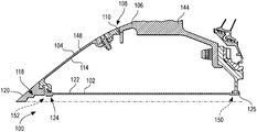
- the nose cone assembly 100 includes a single center connector 102 .
- the single center connector 102 may be a metallic or composite tube, sleeve, threaded bolt, axial clamp, or another suitable connector.
- the single center connector 102 is a tube 122 with a flange/bolt head 124 on one end and threads 125 on the other.
- the tube 122 clamps or ties the nose cone 104 through the center thereof to a blisk hub 106 or conventional rotor disk 40 through axial compression at an outer diameter 107 of a base end 108 of the nose cone 104 .
- the nose cone 104 is coupled to the blisk 106 by the single center bolt connector 102 .
- the single center connector 102 is anchored to a forward end 118 of the nose cone 104 directly behind a tip 120 thereof.
- the tube 122 has disposed near the forward end 118 the bolt head 124 .
- the bolt head 124 is fixedly coupled to the forward end 118 of the nose cone 104 by a threaded locking feature 126 as illustrated in FIG. 6 .
- the threaded locking feature 126 has a generally U-shaped flange 128 that partially surrounds the bolt head 124 and a complementary flange 130 on a back surface of the forward end 118 of the nose cone tip 120 .
- the thread locking feature 126 further includes a cup lock washer 132 formed about the bolt head 124 .
- the bolt head 124 has a plurality of scallops 134 disposed on the outer circumference thereof.
- the scallops 134 align with the generally U-shaped flange 128 such that gaps or cavities 136 are formed between the flange 128 and the outer perimeter of the bolt head 124 .
- a locking piece 138 formed from a piece of sheet metal or another suitably malleable material may be inserted into each gap 136 and then bent in order to deter rotation of the bolt head 124 .
- the cup lock washer 132 By way of the cup lock washer 132 , the axial clamp/tube 122 is anti-rotated from the forward end 118 . Thereby the nose cone 104 is anti-rotated from the forward end 118 .
- a tooling feature 152 for easily attaching, detaching, and re-attaching the nose cone 104 by way of the axial clamp/tube 122 .
- the other end of the tube 122 that has threads 125 is tied into/threaded into an interior portion of the blisk hub 106 .
- the tube single center connector 102 is coupled to both the nose cone 104 and the blisk hub 106 .
- the base end 108 of the nose cone 104 abuts directly to a forward face 110 of the blisk hub 106 .
- the base end 108 of the nose cone 104 may incorporate a spigot 112 (seen in FIG. 7 ).
- the spigot 112 may incorporate an interrupted pilot configuration 116 .
- the spigot 112 of the nose cone 104 interconnects with an interior surface 114 , or socket, of the blisk hub 106 .
- the interrupted pilot 116 of the nose cone base 108 interlocks the spigot 112 with the socket 114 .
- the configuration of the interrupted pilot 116 operates to assist in centering, interlocking, and anti-rotation during operation.
- the interrupted pilot 116 illustrated in FIG. 7 includes a plurality of tabs 140 .
- the tabs 140 extend out from the base end 108 of the nose cone 104 in a generally horizontal direction therefrom.
- the added complexity of the tabs 140 are included in the nose cone 104 rather than further complicating the blisk hub 106 , which is an already relatively more expensive component.
- the forward face 110 of the blisk hub 106 includes blisk forward balance features 142 extending therefrom.
- the blisk forward balance mechanism 142 in this embodiment are scallops 141 that may have holes, blind bores, or added individual balance weights 143 particularly spaced thereon for precise forward balancing.
- blisk 144 This is a significant feature of a blisk 144 because the blisk 144 is not balanced by the modification of pairs of fan blades 36 . Instead, forward balancing is accomplished by the individual balance weights 143 disposed on the scallops 141 . Therefore, blisk balancing in the forward balance plane is retained as a feature of the blisk hub 106 .
- the blisk forward balance features 142 extend inward toward the shaft 38 from an inner diameter of the blisk hub 106 . Therefore, while the blisk hub 106 maintains the forward balance features 142 thereof, the forging envelope is not extended such as by axially extending integral fingers 80 . This simplifies manufacturing thereby saving time and expense.
- the integral fingers 80 are difficult to machine, requiring tight tolerances in addition to the extended forging envelope mentioned hereinabove, the removal thereof saves further time and expense by decreasing mill and mechanized edge profiling (MEP) time.
- the tabs 140 of the interrupted pilot 116 interconnect with the scallops 141 of the blisk hub 106 according to interlocking/interconnecting discussed hereinabove.
- the tabs 140 extend from the nose cone 104 generally transverse to the scalloped blisk forward balance features 142 extending from the forward face 110 of the blisk hub 106 .
- the tabs 140 interfit between the blisk forward balance features 142 (scallops 141 in the example embodiment shown here) thereby interlocking the nose cone 104 with the blisk hub 106 .
- the base end 108 of the nose cone 104 is anti-rotated by the interlocking interrupted pilot configuration 116 thereof.
- the nose cone 104 is anti-rotated from the base end 108 .
- the nose cone 104 is anti-rotated from both the base end 108 , by the interlocking interrupted pilot configuration 116 , and the forward end 118 by the threaded locking feature 126 and cup lock washer 132 with respect to the axial clamp/tube 122 .
- FIG. 8 depicts a nose cone trim balance feature 146 .
- the example embodiment of the nose cone trim balance mechanism 146 depicted is plurality of holes, fasteners, and balance weights used to add a precise amount of mass to a location along the outer surface of the nose cone 104 .
- the nose cone trim balance feature(s) 146 disposed on the nose cone 104 may be significantly tailored and optimized because they are not restricted by the location of the integral fingers 80 or the securing component(s) 76 like the conventional nose cone assembly 56 .
- the quantity and size of the trim balance features 146 are not limited by the circumferential spacing of the blisk hub 106 or the rotor disk 42 .
- the trim balance mechanism 146 may increase the accuracy, precision, and customization of provided trim balance capability as compared with the baseline acceptable trim balancing of the conventional nose cone assembly 56 . Likewise, eliminating the interdependency of the trim balance features 146 from the forward balance features 142 may improve the overall balancing capability and customizability of the turbofan engine 30 .
- the design of the center bolt nose cone assembly 100 also enables the trim balance mechanism 146 to be configured such that the weights thereof are parallel to the incoming airflow and not transverse thereto.
- the fasteners 70 are arranged parallel to a centerline axis of the turbofan engine 30 . This arrangement disposes the fasteners 70 in a more typical bolted flange arrangement, however such an arrangement creates forward facing pockets in the nose cone assembly 56 wherein the fasteners 70 are located. Such pockets are aerodynamically unfavorable and may be detrimental to the fan efficiency because of the air flow disruption caused thereby.
- the nose cone assembly 100 of FIG. 5 enables the fasteners/weights forming the trim balance features 146 to be rotated parallel to the incoming air flow thereby decreasing the aerodynamic loss associated with the axial pockets of the conventional design.
- any axisymmetric features that might simplify the integral fingers or create additional areas for balance may produce obstacles for high cycle fatigue fan blades at the leading edge of the blisk hub 52 .
- Axisymmetric features such as the securing component(s) 76 at the forward face 110 of the blisk hub 52 , may increase stiffness of the blisk 48 attaching to a conventional nose cone assembly 56 and may further raise dynamic stress in a blade leading edge thereof. The stiffness may be corrected for by breaking/interrupting the conventional mount ring 62 beneath (within) a forward rim of the leading edge in order to adapt the conventional fan blisk 48 to the high cycle fatigue (HCF) operating conditions.
- HCF high cycle fatigue
- the stiffness resulting from the securing component(s) 76 and the integral fingers 80 may be removed by replacing said parts with the single center connector 102 of the presently described center bolt nose cone assembly 100 .
- the embodiment depicted further allows for a smooth flow path over the nose cone 104 as the securing components are interior to the nose cone 104 .
- Some conventional designs employ an axially oriented fastening method but such a method creates local forward facing cavities in a conical nose cone surface proximal each fastener thereby increasing loss, decreasing efficiency, and reducing aerodynamic performance.
- the embodiment of FIG. 5 decreases the aerodynamic gap between the base end 108 of the nose cone 104 and the blisk hub 106 or rotor disk 40 .
- center bolt nose cone assembly 100 ties the nose cone 104 to the blisk hub 106 or rotor disk 40 with the single center bolt connector 102 , the two components are secured through axial compression.
- the axial compression further decreases any aerodynamic gaps between the nose cone 104 and the blisk hub 106 or rotor disk 40 by physically pushing the two components together.
- the nose cone 104 is preferably fabricated from aluminum, although other suitable materials may be used.
- An aluminum nose cone may be more easily contoured as compared with composite in order to optimally decrease the weight thereof.
- the overall weight of this portion of the turbofan engine 30 may be reduced, in part resulting from removal of the integral fingers 80 and/or mount ring 62 .
- even further improvements in weight reduction may be realized.
- the single center connector 102 may be incorporated into an already present mechanical low-pressure turbine overspeed system (LPTOSS).
- LPTOSS prevents the axial compressor from exceeding the maximum rotational speed of which the turbofan 34 or blisk 144 is structurally capable. While the axial compressor may reach very high rotational speeds, the turbofan 34 or blisk 144 may not be able to match such speeds without compromising structural integrity and risking catastrophic mechanical failure.
- An LPTOSS configures a reference shaft that abuts the inner diameter of the blisk hub 106 and is in mechanical communication with one or more stages of the compressor such that if the turbofan 34 or blisk 144 is in danger of an overspeed event, fuel injection may be cut-off in anticipation of flameout within the compressor.
- the axial clamp/tube 122 is threaded into/through the reference shaft of modified LPTOSS. This embodiment may further increase weight reduction by tying the axial clamp 122 to an existing component.
- the present disclosure contemplates a nose cone attachment to a fan blisk or rotor disc with a small front circumference that overcomes difficulties in packaging. Furthermore, the nose cone attachment incorporates blisk/disc balance features and reduces cost and weight of the nose cone attachment as well as the overall turbofan stage of an engine.
- the difficulties addressed by the above-described center bolt nose cone assembly are typical for civilian small/medium engine fan sizes.
- the center bolt nose cone assembly may increase cost and weight saves yet further when applied to fan blisk designs with a low hub/tip ratio, such as, for example, less than 0.3.
- An objective of the recent shift in the art toward blisks with integral nose cone attachment fingers/tangs, and away from traditional mount rings, is to reduce cost and weight.
- the current integral finger designs constrain incorporation of blisk forward balance features. For circumferentially restricted designs, this may lead to a lack of design space.
- Fitting a sufficient number of suitably sized fingers for nose cone attachment and trim balance represents a challenge given the number of balance features competing for valuable space at the front of the blisk.
- the center bolt nose cone attachment described hereinabove removes interdependency of forward and trim balance features by attaching the nose cone with an axial clamp. Further design simplification for manufacturing and removal of aerodynamic gaps with the center bolt nose cone attachment may further decrease cost and increase aerodynamic advantages realized by the above-described axially clamped nose cone assembly. Further optimization of the forward and trim balance features as well as application-specific size and manufacturing details may be customized all while adhering to the general principles of the design disclosed herein.
Landscapes
- Engineering & Computer Science (AREA)
- Chemical & Material Sciences (AREA)
- Combustion & Propulsion (AREA)
- Mechanical Engineering (AREA)
- General Engineering & Computer Science (AREA)
- Aviation & Aerospace Engineering (AREA)
- Structures Of Non-Positive Displacement Pumps (AREA)
Abstract
Description
Claims (16)
Priority Applications (3)
| Application Number | Priority Date | Filing Date | Title |
|---|---|---|---|
| US15/211,756 US10612557B2 (en) | 2016-07-15 | 2016-07-15 | Nose cone attachment for turbofan engine |
| CA2945153A CA2945153C (en) | 2016-07-15 | 2016-10-12 | Nose cone attachment for turbofan engine |
| EP17176569.6A EP3269961B1 (en) | 2016-07-15 | 2017-06-19 | Nose cone attachment for turbofan engine |
Applications Claiming Priority (1)
| Application Number | Priority Date | Filing Date | Title |
|---|---|---|---|
| US15/211,756 US10612557B2 (en) | 2016-07-15 | 2016-07-15 | Nose cone attachment for turbofan engine |
Publications (2)
| Publication Number | Publication Date |
|---|---|
| US20180017071A1 US20180017071A1 (en) | 2018-01-18 |
| US10612557B2 true US10612557B2 (en) | 2020-04-07 |
Family
ID=59093401
Family Applications (1)
| Application Number | Title | Priority Date | Filing Date |
|---|---|---|---|
| US15/211,756 Active 2038-10-20 US10612557B2 (en) | 2016-07-15 | 2016-07-15 | Nose cone attachment for turbofan engine |
Country Status (3)
| Country | Link |
|---|---|
| US (1) | US10612557B2 (en) |
| EP (1) | EP3269961B1 (en) |
| CA (1) | CA2945153C (en) |
Families Citing this family (3)
| Publication number | Priority date | Publication date | Assignee | Title |
|---|---|---|---|---|
| US11939872B2 (en) | 2018-11-02 | 2024-03-26 | Tennine Corp. | Miniaturized turbogenerator for the direct electrical propulsion of automotive, urban air mobility, and small marine vehicles |
| US11143103B2 (en) * | 2019-04-10 | 2021-10-12 | Rolls-Royce Corporation | Nose cone and fan assembly |
| US10947995B1 (en) | 2019-08-27 | 2021-03-16 | Pratt & Whitney Canada Corp. | Fan nose cone and dynamic tuning of aircrafts |
Citations (14)
| Publication number | Priority date | Publication date | Assignee | Title |
|---|---|---|---|---|
| US1668972A (en) * | 1928-05-08 | Pbopeller-hub spioteb | ||
| US1730742A (en) * | 1928-12-12 | 1929-10-08 | Hamilton Aero Mfg Company | Cowl for propeller hubs |
| US1773319A (en) * | 1928-02-18 | 1930-08-19 | Bendix Aviat Corp | Propeller spinner |
| US2297226A (en) * | 1937-05-22 | 1942-09-29 | Muller-Keuth Wilhelm | Spinner for the hubs of airscrews |
| US2534662A (en) * | 1948-11-13 | 1950-12-19 | Randall E Froom | Device for attaching propeller spinners |
| US3390527A (en) | 1967-07-19 | 1968-07-02 | Avco Corp | High bypass ratio turbofan |
| US3990814A (en) * | 1975-06-25 | 1976-11-09 | United Technologies Corporation | Spinner |
| US4546604A (en) * | 1979-04-17 | 1985-10-15 | Rolls-Royce Limited | Nose bullet anti-icing for gas turbine engines |
| US4863354A (en) * | 1987-10-07 | 1989-09-05 | Societe Nationale D'etude Et De Construction De Moteurs D'aviation (Snecma) | Nose cowl for a turbojet engine shaft |
| US7303377B2 (en) * | 2004-04-14 | 2007-12-04 | Pratt & Whitney Canada Corp. | Apparatus and method of balancing a shaft |
| US20100051112A1 (en) | 2008-09-03 | 2010-03-04 | Rolls-Royce Deutschland Ltd & Co Kg | Intake cone for a gas-turbine engine |
| US20110236217A1 (en) | 2010-03-26 | 2011-09-29 | Rolls-Royce Plc | Gas turbine engine nose cone |
| US8092183B2 (en) * | 2008-04-24 | 2012-01-10 | Snecma | Fan rotor for a turbomachine or a test engine |
| US10190607B2 (en) * | 2015-01-30 | 2019-01-29 | Goodrich Corporation | Composite actuator piston head assembly |
-
2016
- 2016-07-15 US US15/211,756 patent/US10612557B2/en active Active
- 2016-10-12 CA CA2945153A patent/CA2945153C/en active Active
-
2017
- 2017-06-19 EP EP17176569.6A patent/EP3269961B1/en active Active
Patent Citations (15)
| Publication number | Priority date | Publication date | Assignee | Title |
|---|---|---|---|---|
| US1668972A (en) * | 1928-05-08 | Pbopeller-hub spioteb | ||
| US1773319A (en) * | 1928-02-18 | 1930-08-19 | Bendix Aviat Corp | Propeller spinner |
| US1730742A (en) * | 1928-12-12 | 1929-10-08 | Hamilton Aero Mfg Company | Cowl for propeller hubs |
| US2297226A (en) * | 1937-05-22 | 1942-09-29 | Muller-Keuth Wilhelm | Spinner for the hubs of airscrews |
| US2534662A (en) * | 1948-11-13 | 1950-12-19 | Randall E Froom | Device for attaching propeller spinners |
| US3390527A (en) | 1967-07-19 | 1968-07-02 | Avco Corp | High bypass ratio turbofan |
| US3990814A (en) * | 1975-06-25 | 1976-11-09 | United Technologies Corporation | Spinner |
| US4546604A (en) * | 1979-04-17 | 1985-10-15 | Rolls-Royce Limited | Nose bullet anti-icing for gas turbine engines |
| US4863354A (en) * | 1987-10-07 | 1989-09-05 | Societe Nationale D'etude Et De Construction De Moteurs D'aviation (Snecma) | Nose cowl for a turbojet engine shaft |
| US7303377B2 (en) * | 2004-04-14 | 2007-12-04 | Pratt & Whitney Canada Corp. | Apparatus and method of balancing a shaft |
| US8092183B2 (en) * | 2008-04-24 | 2012-01-10 | Snecma | Fan rotor for a turbomachine or a test engine |
| US20100051112A1 (en) | 2008-09-03 | 2010-03-04 | Rolls-Royce Deutschland Ltd & Co Kg | Intake cone for a gas-turbine engine |
| US8678772B2 (en) | 2008-09-03 | 2014-03-25 | Rolls-Royce Deutschland Ltd & Co Kg | Intake cone for a gas-turbine engine |
| US20110236217A1 (en) | 2010-03-26 | 2011-09-29 | Rolls-Royce Plc | Gas turbine engine nose cone |
| US10190607B2 (en) * | 2015-01-30 | 2019-01-29 | Goodrich Corporation | Composite actuator piston head assembly |
Non-Patent Citations (1)
| Title |
|---|
| Extended European Search Report for European Application No. EP 17176569, dated Dec. 8, 2017 (9 pages). |
Also Published As
| Publication number | Publication date |
|---|---|
| CA2945153C (en) | 2023-11-28 |
| EP3269961B1 (en) | 2020-04-01 |
| CA2945153A1 (en) | 2018-01-15 |
| EP3269961A1 (en) | 2018-01-17 |
| US20180017071A1 (en) | 2018-01-18 |
Similar Documents
| Publication | Publication Date | Title |
|---|---|---|
| EP2221247B1 (en) | Mounting arrangement for a nose cone of a gas turbine engine | |
| US9279326B2 (en) | Method for balancing and assembling a turbine rotor | |
| US9915154B2 (en) | Ceramic matrix composite airfoil structures for a gas turbine engine | |
| US20100226786A1 (en) | Nose cone assembly | |
| US9540939B2 (en) | Gas turbine engine with attached nosecone | |
| EP3026212B1 (en) | Blisk rim face undercut | |
| US9759129B2 (en) | Removable nosecone for a gas turbine engine | |
| EP3252271B1 (en) | Blade assembly, corresponding fan section and gas turbine engine | |
| US11236634B2 (en) | Turbine engine outer shroud | |
| EP3269961B1 (en) | Nose cone attachment for turbofan engine | |
| US20140072437A1 (en) | Turbomachine rotor with a means for axial retention of the blades | |
| US9951654B2 (en) | Stator blade sector for an axial turbomachine with a dual means of fixing | |
| US20160195015A1 (en) | Gas turbine engine nosecone attachment structure | |
| US8511971B2 (en) | One-piece compressor and turbine containment system | |
| EP3115555B1 (en) | Integrally bladed rotor portion, corresponding hybrid rotor and gas turbine engine | |
| KR20080018821A (en) | Method and apparatus for manufacturing rotor for steam turbine | |
| EP3348785B1 (en) | Anti-rotation lock for threaded in place nosecone or spinner | |
| EP3441562A1 (en) | Fan disc apparatus | |
| US10371162B2 (en) | Integrally bladed fan rotor | |
| US12320275B2 (en) | Stator vane assembly for an aircraft turbine engine compressor | |
| EP3425167B1 (en) | Rotary machines including a hybrid rotor with hollow and solid rotor blade sets | |
| US20210123355A1 (en) | System for an improved stator assembly |
Legal Events
| Date | Code | Title | Description |
|---|---|---|---|
| AS | Assignment |
Owner name: ROLLS-ROYCE CORPORATION, INDIANA Free format text: ASSIGNMENT OF ASSIGNORS INTEREST;ASSIGNOR:HALL, CHRISTOPHER;REEL/FRAME:039285/0369 Effective date: 20160714 |
|
| STPP | Information on status: patent application and granting procedure in general |
Free format text: NON FINAL ACTION MAILED |
|
| STPP | Information on status: patent application and granting procedure in general |
Free format text: RESPONSE TO NON-FINAL OFFICE ACTION ENTERED AND FORWARDED TO EXAMINER |
|
| STPP | Information on status: patent application and granting procedure in general |
Free format text: FINAL REJECTION MAILED |
|
| STPP | Information on status: patent application and granting procedure in general |
Free format text: RESPONSE AFTER FINAL ACTION FORWARDED TO EXAMINER |
|
| STPP | Information on status: patent application and granting procedure in general |
Free format text: NOTICE OF ALLOWANCE MAILED -- APPLICATION RECEIVED IN OFFICE OF PUBLICATIONS |
|
| STPP | Information on status: patent application and granting procedure in general |
Free format text: PUBLICATIONS -- ISSUE FEE PAYMENT RECEIVED |
|
| STCF | Information on status: patent grant |
Free format text: PATENTED CASE |
|
| MAFP | Maintenance fee payment |
Free format text: PAYMENT OF MAINTENANCE FEE, 4TH YEAR, LARGE ENTITY (ORIGINAL EVENT CODE: M1551); ENTITY STATUS OF PATENT OWNER: LARGE ENTITY Year of fee payment: 4 |