US10608490B2 - Axial flux machine - Google Patents
Axial flux machine Download PDFInfo
- Publication number
- US10608490B2 US10608490B2 US15/295,239 US201615295239A US10608490B2 US 10608490 B2 US10608490 B2 US 10608490B2 US 201615295239 A US201615295239 A US 201615295239A US 10608490 B2 US10608490 B2 US 10608490B2
- Authority
- US
- United States
- Prior art keywords
- rotor
- stator
- machine
- shaft
- axial
- Prior art date
- Legal status (The legal status is an assumption and is not a legal conclusion. Google has not performed a legal analysis and makes no representation as to the accuracy of the status listed.)
- Active, expires
Links
- 230000004907 flux Effects 0.000 title claims abstract description 64
- 230000005540 biological transmission Effects 0.000 claims abstract description 9
- 125000006850 spacer group Chemical group 0.000 claims description 120
- 238000000034 method Methods 0.000 claims description 73
- 230000004323 axial length Effects 0.000 claims description 24
- 230000005291 magnetic effect Effects 0.000 claims description 19
- 230000008878 coupling Effects 0.000 claims description 8
- 238000010168 coupling process Methods 0.000 claims description 8
- 238000005859 coupling reaction Methods 0.000 claims description 8
- 239000002826 coolant Substances 0.000 claims description 7
- 230000033001 locomotion Effects 0.000 claims description 7
- 238000009434 installation Methods 0.000 description 11
- XEEYBQQBJWHFJM-UHFFFAOYSA-N Iron Chemical compound [Fe] XEEYBQQBJWHFJM-UHFFFAOYSA-N 0.000 description 9
- 230000008569 process Effects 0.000 description 6
- 229910052742 iron Inorganic materials 0.000 description 5
- 238000013459 approach Methods 0.000 description 4
- 238000011900 installation process Methods 0.000 description 4
- 238000004519 manufacturing process Methods 0.000 description 3
- 239000000463 material Substances 0.000 description 3
- 239000002245 particle Substances 0.000 description 3
- 230000015556 catabolic process Effects 0.000 description 2
- 238000009413 insulation Methods 0.000 description 2
- 238000000926 separation method Methods 0.000 description 2
- 238000004804 winding Methods 0.000 description 2
- 230000000712 assembly Effects 0.000 description 1
- 238000000429 assembly Methods 0.000 description 1
- 238000005452 bending Methods 0.000 description 1
- 230000009286 beneficial effect Effects 0.000 description 1
- 230000008901 benefit Effects 0.000 description 1
- 238000005056 compaction Methods 0.000 description 1
- 238000001816 cooling Methods 0.000 description 1
- 230000001419 dependent effect Effects 0.000 description 1
- 238000006073 displacement reaction Methods 0.000 description 1
- 238000010292 electrical insulation Methods 0.000 description 1
- 230000005294 ferromagnetic effect Effects 0.000 description 1
- 239000011521 glass Substances 0.000 description 1
- 230000010354 integration Effects 0.000 description 1
- 238000003475 lamination Methods 0.000 description 1
- 230000007774 longterm Effects 0.000 description 1
- 239000011159 matrix material Substances 0.000 description 1
- 238000012986 modification Methods 0.000 description 1
- 230000004048 modification Effects 0.000 description 1
- 230000002093 peripheral effect Effects 0.000 description 1
- 230000008439 repair process Effects 0.000 description 1
Images


Classifications
-
- H—ELECTRICITY
- H02—GENERATION; CONVERSION OR DISTRIBUTION OF ELECTRIC POWER
- H02K—DYNAMO-ELECTRIC MACHINES
- H02K1/00—Details of the magnetic circuit
- H02K1/06—Details of the magnetic circuit characterised by the shape, form or construction
- H02K1/22—Rotating parts of the magnetic circuit
- H02K1/27—Rotor cores with permanent magnets
- H02K1/2793—Rotors axially facing stators
- H02K1/2795—Rotors axially facing stators the rotor consisting of two or more circumferentially positioned magnets
- H02K1/2798—Rotors axially facing stators the rotor consisting of two or more circumferentially positioned magnets where both axial sides of the stator face a rotor
-
- H—ELECTRICITY
- H02—GENERATION; CONVERSION OR DISTRIBUTION OF ELECTRIC POWER
- H02K—DYNAMO-ELECTRIC MACHINES
- H02K15/00—Processes or apparatus specially adapted for manufacturing, assembling, maintaining or repairing of dynamo-electric machines
- H02K15/02—Processes or apparatus specially adapted for manufacturing, assembling, maintaining or repairing of dynamo-electric machines of stator or rotor bodies
- H02K15/03—Processes or apparatus specially adapted for manufacturing, assembling, maintaining or repairing of dynamo-electric machines of stator or rotor bodies having permanent magnets
-
- H—ELECTRICITY
- H02—GENERATION; CONVERSION OR DISTRIBUTION OF ELECTRIC POWER
- H02K—DYNAMO-ELECTRIC MACHINES
- H02K1/00—Details of the magnetic circuit
- H02K1/06—Details of the magnetic circuit characterised by the shape, form or construction
- H02K1/12—Stationary parts of the magnetic circuit
- H02K1/14—Stator cores with salient poles
- H02K1/146—Stator cores with salient poles consisting of a generally annular yoke with salient poles
-
- H—ELECTRICITY
- H02—GENERATION; CONVERSION OR DISTRIBUTION OF ELECTRIC POWER
- H02K—DYNAMO-ELECTRIC MACHINES
- H02K15/00—Processes or apparatus specially adapted for manufacturing, assembling, maintaining or repairing of dynamo-electric machines
-
- H—ELECTRICITY
- H02—GENERATION; CONVERSION OR DISTRIBUTION OF ELECTRIC POWER
- H02K—DYNAMO-ELECTRIC MACHINES
- H02K15/00—Processes or apparatus specially adapted for manufacturing, assembling, maintaining or repairing of dynamo-electric machines
- H02K15/16—Centring rotors within the stators
-
- H—ELECTRICITY
- H02—GENERATION; CONVERSION OR DISTRIBUTION OF ELECTRIC POWER
- H02K—DYNAMO-ELECTRIC MACHINES
- H02K16/00—Machines with more than one rotor or stator
- H02K16/02—Machines with one stator and two or more rotors
-
- H—ELECTRICITY
- H02—GENERATION; CONVERSION OR DISTRIBUTION OF ELECTRIC POWER
- H02K—DYNAMO-ELECTRIC MACHINES
- H02K21/00—Synchronous motors having permanent magnets; Synchronous generators having permanent magnets
- H02K21/12—Synchronous motors having permanent magnets; Synchronous generators having permanent magnets with stationary armatures and rotating magnets
- H02K21/24—Synchronous motors having permanent magnets; Synchronous generators having permanent magnets with stationary armatures and rotating magnets with magnets axially facing the armatures, e.g. hub-type cycle dynamos
-
- H—ELECTRICITY
- H02—GENERATION; CONVERSION OR DISTRIBUTION OF ELECTRIC POWER
- H02K—DYNAMO-ELECTRIC MACHINES
- H02K5/00—Casings; Enclosures; Supports
- H02K5/04—Casings or enclosures characterised by the shape, form or construction thereof
- H02K5/16—Means for supporting bearings, e.g. insulating supports or means for fitting bearings in the bearing-shields
- H02K5/161—Means for supporting bearings, e.g. insulating supports or means for fitting bearings in the bearing-shields radially supporting the rotary shaft at both ends of the rotor
-
- H—ELECTRICITY
- H02—GENERATION; CONVERSION OR DISTRIBUTION OF ELECTRIC POWER
- H02K—DYNAMO-ELECTRIC MACHINES
- H02K5/00—Casings; Enclosures; Supports
- H02K5/04—Casings or enclosures characterised by the shape, form or construction thereof
- H02K5/16—Means for supporting bearings, e.g. insulating supports or means for fitting bearings in the bearing-shields
- H02K5/173—Means for supporting bearings, e.g. insulating supports or means for fitting bearings in the bearing-shields using bearings with rolling contact, e.g. ball bearings
-
- H—ELECTRICITY
- H02—GENERATION; CONVERSION OR DISTRIBUTION OF ELECTRIC POWER
- H02K—DYNAMO-ELECTRIC MACHINES
- H02K7/00—Arrangements for handling mechanical energy structurally associated with dynamo-electric machines, e.g. structural association with mechanical driving motors or auxiliary dynamo-electric machines
- H02K7/006—Structural association of a motor or generator with the drive train of a motor vehicle
-
- H—ELECTRICITY
- H02—GENERATION; CONVERSION OR DISTRIBUTION OF ELECTRIC POWER
- H02K—DYNAMO-ELECTRIC MACHINES
- H02K7/00—Arrangements for handling mechanical energy structurally associated with dynamo-electric machines, e.g. structural association with mechanical driving motors or auxiliary dynamo-electric machines
- H02K7/08—Structural association with bearings
- H02K7/083—Structural association with bearings radially supporting the rotary shaft at both ends of the rotor
-
- H—ELECTRICITY
- H02—GENERATION; CONVERSION OR DISTRIBUTION OF ELECTRIC POWER
- H02K—DYNAMO-ELECTRIC MACHINES
- H02K2201/00—Specific aspects not provided for in the other groups of this subclass relating to the magnetic circuits
- H02K2201/03—Machines characterised by aspects of the air-gap between rotor and stator
-
- H—ELECTRICITY
- H02—GENERATION; CONVERSION OR DISTRIBUTION OF ELECTRIC POWER
- H02K—DYNAMO-ELECTRIC MACHINES
- H02K7/00—Arrangements for handling mechanical energy structurally associated with dynamo-electric machines, e.g. structural association with mechanical driving motors or auxiliary dynamo-electric machines
- H02K7/08—Structural association with bearings
- H02K7/085—Structural association with bearings radially supporting the rotary shaft at only one end of the rotor
-
- H—ELECTRICITY
- H02—GENERATION; CONVERSION OR DISTRIBUTION OF ELECTRIC POWER
- H02K—DYNAMO-ELECTRIC MACHINES
- H02K7/00—Arrangements for handling mechanical energy structurally associated with dynamo-electric machines, e.g. structural association with mechanical driving motors or auxiliary dynamo-electric machines
- H02K7/14—Structural association with mechanical loads, e.g. with hand-held machine tools or fans
-
- H—ELECTRICITY
- H02—GENERATION; CONVERSION OR DISTRIBUTION OF ELECTRIC POWER
- H02K—DYNAMO-ELECTRIC MACHINES
- H02K7/00—Arrangements for handling mechanical energy structurally associated with dynamo-electric machines, e.g. structural association with mechanical driving motors or auxiliary dynamo-electric machines
- H02K7/18—Structural association of electric generators with mechanical driving motors, e.g. with turbines
- H02K7/1807—Rotary generators
- H02K7/1815—Rotary generators structurally associated with reciprocating piston engines
Definitions
- the present invention relates to an axial flux machine, in particular a method of pre-assembly for shipment and subsequent assembly into another machine.
- FIG. 1 a shows the general configuration of an axial flux machine of the present invention with a pair of rotors R 1 , R 2 to either side of a stator S—although a simple structure of the present invention could omit one of the rotors.
- an air gap G between a rotor and a stator and in an axial flux machine the direction of flux through the air gap is substantially axial.
- FIG. 1 b illustrates the basic configurations of a Torus NS machine, a Torus NN machine (which has a thicker yoke because the NN pole arrangement requires flux to flow through the thickness of the yoke), and a YASA (Yokeless and Segmented Armature) topology.
- the illustration of the YASA topology shows cross-sections through two coils, the cross-hatched area showing the windings around each coil.
- stator yoke provides a substantial saving in weight and iron losses, but one drawback is loss of rigid structure in which a bearing can be mounted to support rotors.
- a bearing is mounted within the stator confines and magnetic forces from rotors on either side of the stator are axially balanced.
- Rotors being designed to resist bending towards the stator.
- the air gap between rotor and stator for axial flux motors is small typically of the order of 1 mm. Smaller gaps lead to higher motor torque and power output and is seen as beneficial.
- WO 2010/092402 teaches a two stage rotor arranged one at either end of the stator bars, with two air gaps between the ends of the bars and the rotor stages, an annular housing retaining and mounting the stator; a bearing between the rotor and stator.
- the rotor is thus not otherwise supported in or on the housing and air gaps are set by stator width, bearing length and bearing support faces on rotors.
- Oudet teaches rough axial placement of the rotor shaft and rotor support using a circlip and shims and fine alignment by sandwiching the rotor part between stator parts, keeping an air gap using two spacers and fixing or (adhesively) sticking rotor and stator components when placed, thereby maintaining their relative positions.
- the present invention therefore provides a method of assembling an axial flux machine comprising: supplying a shaft, the shaft extending along an axis of the machine and comprising first and second rotor contact surfaces for mounting first and second rotors; attaching a first rotor to an outer surface of the shaft at the first rotor contact surface, the first rotor comprising an annulus having a hollow central region and having a set of permanent magnets disposed circumferentially at intervals around the axis of the machine facing inward of the machine; applying a spacer to the first rotor, the spacer for spacing the first rotor and a stator apart; arranging a stator co-axially with the shaft and adjacent the first rotor such that the spacer is contacted by a first side of the stator and the first rotor, the stator comprising a stator housing enclosing a plurality of stator bars disposed circumferentially at intervals around the axis of the machine, each of the stator bars having a
- the present invention provides a solution to safe assembly of rotor and stator components of a bearingless axial flux motor for handling and shipping purposes.
- the spacer may be applied to a surface of the first rotor that faces the stator, the spacer being formed of an annulus with a channel between the inner and outer circumferential portions for receiving the shaft. Such a spacer prevents touchdown between the first rotor and stator during transit.
- the method may comprise applying a second spacer between the second surface of the stator and the second rotor.
- the second spacer may formed of an annulus with a channel between the inner and outer circumferential portions for receiving the shaft.
- the second spacer may have an axial thickness that is greater than a desired air-gap between the second rotor and stator of the assembled machine. Such a second spacer prevents damage occurring to the stator housing or the second rotor if the stator is caused to “hop” away from engagement with the first spacer during transportation of the machine.
- the spacer in contact with the first rotor may have an axial thickness that is less than a desired air-gap between the first rotor and stator of the assembled machine.
- An alternative spacer may be mounted to a surface of the first rotor that faces away from the stator, where the spacer is formed as an annulus comprising a plurality of spacing portions extending radially from the outer circumference of the annulus beyond the circumferential edge of the first rotor.
- the spacing portions extend axially towards the stator, and wherein the spacer portions are in contact with the first side of the stator when installed.
- the axial length of the spacer portions defines a gap between the stator and the rotor when installed.
- the spacer may be attached to the stator to prevent the stator moving around.
- the rotors are attached to the shaft by push-fit, bolt or screw fixings, or hot shrink fit.
- the method further comprises attaching a mount to the second side of the stator housing, the mount having a mount surface facing away from the stator housing for mounting the machine to a structure.
- the present invention also provides a method of installing an axial flux machine to a structure.
- the method comprises: assembling an axial flux machine as described above with reference to the use of the first type of spacer; supporting the shaft in axial alignment with the structure and at an axial position relative to the structure; attaching the second side of the stator housing to the structure; and removing the spacer, wherein the step of attaching the second side of the stator housing to the structure pulls the stator away from the first rotor such that the stator is moved axially to be centered axially between the first and second rotors.
- the present invention also provides a method of installing an axial flux machine to a structure.
- the method comprises: assembling an axial flux machine as described with reference to the use of the second type spacer; supporting the shaft in axial alignment with the structure and at an axial position relative to the structure; attaching the second side of the stator housing to the structure; and removing the spacer.
- the shaft of the machine comprises a first engagement surface on a first end of the shaft for coupling torque in or out of the machine, a second engagement surface at a second end of the shaft for coupling torque in or out of the machine, a first radial bearing mounting surface on the first end of the shaft and a second radial bearing mounting surface on the second end of the shaft, wherein the first end of the shaft is on the same side of the machine as the first rotor and the second end of the shaft is on the same side of the machine as the second rotor.
- the step of attaching the second side of the stator housing to the structure may comprise: arranging the structure on to the shaft at the second end of the shaft, the structure comprising a second radial bearing on an inner circumferential surface of a hollow portion in the structure, and the structure being supported on the shaft by the second radial bearing, the second radial bearing being seated on the shaft at the second radial bearing mounting surface; providing an axial shim in an axial path between the structure and stator housing; and attaching the second side of the stator housing to the structure, wherein the axial shim has a thickness that defines an axial position of the structure relative to the stator housing such that when the structure is driven into attachment with the mount, the stator moves axially away from the first rotor to a central axial location between the first and second rotors.
- the machine may comprise a mount having a mounting surface and for mounting the stator housing and structure, the method of attaching the second side of the stator housing further comprises: attaching the mount to the second side of the stator housing, the mounting surface facing away from the stator housing; and attaching the mounting surface to the structure.
- the axial shim may be provided between the structure and second radial bearing, between the second radial bearing and the second radial bearing mounting surface, or between the structure and the stator housing, or, when there is a mount, between the structure and the mounting surface of the mount.
- the step of providing an axial shim may comprises: measuring at least one axial length of a portion within the machine; and selecting an axial shim thickness depending on the at least one measured axial length such that the step of attaching the mount to the structure causes sufficient axial movement of the stator in order to move the stator axially away from the first rotor.
- the at least one measured axial length of a portion within the machine is one or more of: an axial distance between the second radial bearing mounting surface and the first rotor; an axial distance between the first and second rotor contact surfaces; an axial distance between the second radial bearing mount surface and the second rotor contact surface; an axial length of the structure between the surface of the second radial bearing in contact with the second radial bearing mount surface and the surface of the structure in contact with the mount surface of the mount; and an axial distance of the mount between the mount surface and the surface of the mount in contact with the stator housing.
- the spacer is preferably released from between the first rotor and stator.
- the structure may covers or enclose the second rotor. If a mount is used, the structure and/or the mount may cover or enclose the second rotor to protect it from the external environment.
- the method may also comprise: attaching the first side of the stator housing to a second structure.
- the step of attaching the first side of the stator housing to a second structure may comprise: arranging a second structure on to the shaft at the first end of the shaft, the second structure comprising a first radial bearing on an inner circumferential surface of a hollow portion in the second structure, and the second structure being supported on the shaft by the first radial bearing, the first radial bearing being seated on the shaft at the first radial bearing mounting surface; and attaching the second side of the stator housing to the second structure.
- the machine may comprise a second mount having a mounting surface and for mounting the stator housing and second structure, the method of attaching the first side of the stator housing further comprising: attaching a second mount to the first side of the stator housing, the second mount having a mounting surface at an end of the second mount away from the stator housing; and attaching the mounting surface of the second mount to the second structure.
- the second structure may cover or enclose the first rotor. If a second mount is used, the second structure and/or the second mount may cover or enclose the first rotor to protect it from the external environment.
- the second structure preferably supports the shaft in axial alignment with the first structure and axial position in the first structure.
- the structures may comprise a portion of an engine of a vehicle or a portion of a transmission system of the vehicle.
- the present invention also provides an axial flux machine mounted to a structure comprising: a stator comprising a stator housing enclosing a plurality of stator bars disposed circumferentially at intervals around an axis of the machine, each of the stator bars having a set of coils wound therearound for generating a magnetic field, and the stator housing having an annular shape forming a hollow region about the axis of the machine; a first rotor comprising a set of permanent magnets and mounted for rotation about the axis of the machine, the rotor being spaced apart from the stator along the axis of the machine to define a gap between the stator and rotor and in which magnetic flux in the machine is generally in an axial direction, and the rotor formed of an annulus and having a hollow central region about the axis of the machine; a second rotor disposed on an opposite side of the stator to the first rotor, the second rotor comprising a set of permanent magnets on a first side
- the machine may comprise a mount between the second side of the stator housing and the structure, wherein the mount comprises a mounting surface facing away from the stator housing, and wherein the structure is mounted to the mounting surface of the mount, and the second side of the stator housing is mounted to the mount.
- the machine may also comprise an axial shim between the structure and second radial bearing, between the second radial bearing and the second radial bearing mounting surface, or between the mount and the stator housing, or, when there is a mount, between the structure and the mount surface of the mount.
- the axial shim may have a thickness that defines an axial position of the structure relative to the stator housing.
- the first rotor contact surface may be axially positioned on the shaft to define the axial position of the first rotor, and wherein the second rotor contact surface is axially separated from the first rotor contact surface to define the axial distance between the first and second rotors and to define the axial airgaps between the first rotor and stator and the second rotor and stator.
- the structure may covers or enclose the second rotor.
- the structure and/or mount may cover or enclose the second rotor.
- the machine may also be mounted to a second structure, wherein the second structure is arranged on the shaft at the first end of the shaft and attached to the first side of the stator housing, the second structure comprising a first radial bearing on an inner circumferential surface of a hollow portion in the second structure, and the second structure being supported on the shaft by the first radial bearing, the first radial bearing being seated on the shaft at the first radial bearing mounting surface.
- the may also be provided a second mount between the first side of the stator housing and the second structure, wherein the mount comprises a mounting surface facing away from the first side of the stator housing, and wherein the second structure is mounted to the mounting surface of the second mount, and the first side of the stator housing is mounted to the mount.
- the second structure may cover or enclose the first rotor.
- the second structure and/or second mount may cover or enclose the first rotor.
- the above-mentioned structures may comprise a portion of an engine of a vehicle or a portion of a transmission system of the vehicle.
- the present invention may also provide an axial flux machine comprising: a stator comprising a stator housing enclosing a plurality of stator bars disposed circumferentially at intervals around an axis of the machine, each of the stator bars having a set of coils wound therearound for generating a magnetic field, and the stator housing having an annular shape forming a hollow region about the axis of the machine; a first rotor comprising a set of permanent magnets and mounted for rotation about the axis of the machine, the rotor being spaced apart from the stator along the axis of the machine to define a gap between the stator and rotor and in which magnetic flux in the machine is generally in an axial direction, and the rotor formed of an annulus and having a hollow central region about the axis of the machine; a second rotor disposed on an opposite side of the stator to the first rotor, the second rotor comprising a set of permanent magnets on a first side of the second
- the spacer may be between the first rotor and first side of the stator and in contact with the first rotor and first side of the stator.
- the spacer may be formed of an annulus with a channel between the inner and outer circumferential portions for receiving the shaft.
- the machine may also be provided with a second spacer in between the second rotor and the second side of the stator, which protects the stator housing and second rotor from damage during transit should the stator be caused to “hop” from its contact with the first spacer on the first side of the machine.
- the second spacer may have an axial thickness that is greater than a desired air-gap between the second rotor and stator of the assembled machine.
- the spacer in contact with the first rotor may have an axial thickness that is less than a desired air-gap between the first rotor and stator of the assembled machine.
- the spacer may be mounted to a surface of the first rotor that faces away from the stator.
- This spacer may be formed as an annulus comprising a plurality of spacing portions extending radially from the outer circumference of the annulus beyond the circumferential edge of the first rotor, the spacing portions also extending axially towards the stator, and wherein the spacer portions are in contact with the first side of the stator when installed.
- the axial length of the spacer portions defines a gap between the stator and the rotor when installed.
- the spacer may be attached to the stator to prevent the stator moving around.
- the machine may also comprise a mount to the second side of the stator housing, the mount having a mount surface facing away from the stator housing for mounting the machine to a structure.
- first and/or second engagement surfaces may comprise splines for engagement with respective shafts.
- the stator housing may define a chamber incorporating cooling medium in contact with the coils to cool the coils, the stator housing including a port for supply and a port for drainage of the cooling medium.
- the machine is a torque source, a motor or generator.
- FIGS. 1 a to 1 c show, respectively, a general configuration of a two-rotor axial flux machine, example topologies for axial flux permanent magnet machines, and a schematic side view of a yokeless and segmented armature (YASA) machine;
- YASA yokeless and segmented armature
- FIG. 2 shows a perspective view of the YASA machine of FIG. 1 c
- FIG. 3 shows a perspective exploded view of a stator and stator housing for a YASA machine
- FIGS. 4 a, b and c show assembled axial flux machines installed on other structures
- FIG. 5 shows the axial flux machine of FIG. 4 using a first type of spacer during assembly
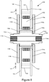
- FIG. 6 shows the axial flux machine of FIG. 4 using a first type of spacer during assembly
- FIG. 7 shows the first type of spacer
- FIG. 8 shows the axial flux machine of FIG. 4 using the first type of spacer during assembly
- FIG. 9 shows the axial flux machine of FIG. 4 using a second type of spacer during assembly
- FIG. 10 shows the axial flux machine of FIG. 4 using a second type of spacer during assembly
- FIG. 11 shows the axial flux machine of FIG. 4 using a second type of spacer during assembly
- FIGS. 12 a and 12 b show the second type of spacer
- FIG. 13 shows the assembled axial flux machine of FIG. 4 using a first type of spacer during installation
- FIG. 14 shows the assembly of the axial flux machine of FIG. 4 using a second type of spacer during installation
- FIG. 16 shows the assembly of the axial flux machine of FIG. 4 using a second type of spacer during installation
- FIG. 1 c shows a schematic illustration of a yokeless and segmented armature machine 10 .
- the machine 10 comprises a stator 12 and two rotors 14 a,b .
- the stator 12 is a collection of separate stator bars 16 spaced circumferentially about a rotation axis 20 of the rotors 14 a,b .
- Each bar 16 has its own axis (not shown) which is preferably, but not essentially, disposed parallel to the rotation axis 20 .
- Each end of each stator bar is provided with a shoe 18 a,b which serves a physical purpose of confining a coil stack 22 , which stack 22 is preferably of square/rectangular section insulated wire so that a high fill factor can be achieved.
- the coils 22 are connected to an electrical circuit (not shown) that, in the case of a motor, energizes the coils so that the poles of the resultant magnetic fields generated by the current flowing in the coils is opposite in adjacent stator coils 22 .
- the two rotors 14 a,b carry permanent magnets 24 a, b that face one another with the stator coil 22 between (when the stator bars are inclined—not as shown—the magnets are likewise).
- Two air gaps 26 a,b are disposed between respective shoe and magnet pairs 18 a / 24 a , 18 b / 24 b .
- the coils 22 are energized so that their polarity alternates serving to cause coils at different times to align with different magnet pairs, resulting in torque being applied between the rotor and the stator.
- the rotors 14 a,b are generally connected together (for example by a shaft, not shown) and rotate together about the axis 20 relative to the stator 12 .
- the magnetic circuit 30 is provided by two adjacent stator bars 16 and two magnet pairs 24 a,b and a back iron 32 a,b for each rotor links the flux between the back of each magnet 24 a,b facing away from the respective coils 22 .
- the stator coils 16 are enclosed within a housing that extends through the air gap 26 a, b and which defines a chamber supplied with a cooling medium.
- FIG. 3 a stator 12 a is shown in which the stator coils are located between plastic material clam shells 42 a, b . These clamshells have external cylindrical walls 44 , internal cylindrical walls 46 , and annular radially disposed walls 48 .
- the radial walls 48 include internal pockets 50 to receive the shoes 18 a,b of the stator bars 16 and serve to locate the stator coil assemblies 16 , 22 , 18 a,b when the two clam shell housings 42 a, b of the stator 12 a are assembled together.
- the stator housing 42 a, b defines spaces 52 internally of the coils 22 and externally at 54 around the outside of the coils 22 and there are spaces 56 between the coils.
- the spaces 52 , 54 , 56 are interlinked defining a cooling chamber.
- the stator housing 42 a,b is provided with ports that allow cooling medium such as oil to be pumped into the spaces 52 , 54 , 56 to circulate around the coils and cool them.
- the coil cores may be laminated with the inter-lamination insulation parallel to the desired flux direction.
- the coil cores may also be formed from soft-iron particles coated with electrical insulation and moulded to a desired shape (soft magnetic composites—SMC), being bound together by the insulation matrix.
- SMC soft magnetic composites
- An example SMC may comprise glass-bonded iron particles, a thin layer (typically ⁇ 10 ⁇ m) of glass bonding and mutually electrically insulating the iron particles, leaving some residual porosity.
- a high-temperature, high-pressure compaction process is used to mould the component into a complex shape, capable of producing three-dimensional magnetic flux patterns with an excellent form factor and enabling a high fill factor winding to be employed, wound straight onto SMC teeth.
- the shoes and stator bar may be formed separately and subsequently assembled; a shoe may have a central region with an axial direction of minimum reluctance and an outer region with a radial direction of minimum reluctance (see WO2012/022974).
- FIGS. 4 to 17 show the axial flux machine 100 during various stages of assembly and installation.
- FIG. 4 a shows the machine fully assembled and installed within the structures 108 , 110 .
- FIGS. 4 b and 4 c show different variants of the machine assembled and installed within the structure 108 (no second structure is shown here, but may be present when fully assembled).
- FIGS. 5 to 8 show the machine in various states of assembly when using a first type of spacer.
- FIGS. 9 to 12 show the machine in various states of assembly when using a second type of spacer.
- FIGS. 5 to 12 when fully assembled, the machine is in a condition in which it may be transported to be installed into suitable structures (such as the arrangement shown in FIG. 4 ).
- FIG. 13 shows the installation process when using the first type of spacer.
- FIGS. 14 to 17 show the installation process when using the second type of spacer.
- the axial flux machine 100 comprises a stator 102 and a rotor 104 , which has two stages 104 a, b , disposed either side of the stator 102 and axially spaced apart from the stator to provide axial air gaps.
- a shaft 106 extends along the axis of the machine and has first and second engagement surfaces 116 a,b that enable other shafts or suitable connections to be made to the machine in order to get torque in or out of the machine when installed.
- the engagement surfaces 116 a,b are shown as splined surfaces, although other types of engagement would be apparent to the reader, such as the bolts 136 ( FIG. 4 b ), which affix the shaft 106 to the shaft of the structure, or the splined surfaces 138 in FIG. 4 c.
- the first and second rotors 104 a,b are mounted to the shaft via, respectively, first rotor contact surface 130 a and second rotor contact surface 130 b .
- the first rotor contact surface 130 a is axially positioned on the shaft 106 to define the axial position of the first rotor 104 a
- the second rotor contact surface 130 b is axially separated from the first rotor contact surface 130 a to define the axial distance between the first and second rotors 104 a,b and to define the axial airgaps between the first rotor 104 a and stator 102 and the second rotor 104 b and stator 102 .
- the stator 102 has a housing 120 comprising first and second radial walls and generally cylindrical inner and outer walls, defining a chamber within which coolant may circulate.
- the housing encloses a set of stator coils; these and their electrical connections are not shown for simplicity.
- the coils are wound around pole pieces (also not shown for simplicity).
- a second structure may not be required.
- a second shaft bearing (not shown) situated to the left of the bearing seen in FIGS. 4 b and 4 c may be used to form a cantilever bearing shaft obviating need for a supporting structure 110 .
- a rotor cover (not shown) may be used to protect rotor 104 a from the external environment.
- the structure 108 has an opening to receive the second end of the shaft 106 and it's second engagement surface 116 b .
- the structure 108 in it's opening, has radial bearings 134 b seated therein. When installed, the bearings 134 b are seated on the second end of the shaft 106 and rest up against the second bearing contact surface 132 b .
- the structure 108 is supported on the shaft 106 via the radial bearings 134 b , and the structure 108 and/or the mount 126 may cover or enclose the second rotor 104 b , which protects the rotating rotor 104 b from the external environment.
- the structure 108 may, for example, be a portion of an engine in a vehicle e.g. a flywheel bell housing, to which the machine 100 is to be mounted to provide torque or additional torque e.g. for starting (in the case of the machine being a motor or torque source) or to receive torque from the engine (in the case of the machine being a generator).
- a vehicle e.g. a flywheel bell housing
- additional torque e.g. for starting (in the case of the machine being a motor or torque source) or to receive torque from the engine (in the case of the machine being a generator).
- the machine 100 may be mounted to the structure 108 via a mount 126 , which is mounted to the stator housing 120 .
- the shaft 106 and thus rotors 104 a,b may rotate relative to the stator housing 120 , mount 126 and the structure 108 .
- This arrangement provides a very rigid structure, which provides correct alignment for the rotors 104 a,b , stator 102 and shaft 106 and also may provide cover or enclosure to the second rotor 104 b .
- the function of the separate mount 126 is provided by a suitable mount structure that is integral either with the stator housing 120 or the structure 108 and that extends from the stator housing or structure.
- an axial shim 140 is required in order to provide the correct position of the stator housing 120 relative to the rotors 104 a,b and the structure 108 . If this is the case, the shim 140 may be located in one or more of the following positions:
- the second structure 110 has an opening to receive the first end of the shaft 106 and its first engagement surface 116 a .
- the structure 110 in it's opening, has radial bearings 134 a seated therein. When installed, the bearings 134 a are seated on the first end of the shaft 106 and rest up against the first bearing contact surface 132 a .
- the structure 110 supports the shaft 106 via the radial bearings 134 a , and the structure 110 may cover or enclose the first rotor 104 a , which protects the rotating rotor 104 a from the external environment.
- the structure 110 may, for example, be a portion of a transmission system in a vehicle (such as a clutch assembly or a gearbox), to which the machine 100 is to be mounted to provide additional torque (in the case of the machine being a motor or torque source) or to receive torque from the engine (in the case of the machine being a generator).
- a vehicle such as a clutch assembly or a gearbox
- the machine 100 may be mounted to the structure 110 via a second mount 128 , which is mounted to the stator housing 120 .
- the shaft 106 and thus rotors 104 a,b may rotate relative to the stator housing 120 and the structure 110 .
- This arrangement provides a very rigid structure, and also provides correct alignment for the rotors 104 a,b , stator 102 and shaft 106 .
- the function of the second mount 128 is provided by a suitable mount structure that is integral either with the stator housing 120 or the structure 110 and that extends from the stator housing or structure.
- FIGS. 6 and 8 show the machine 100 in its assembled, but uninstalled form when using a first type of spacer 122 , 126 .
- FIG. 8 additionally shows a second spacer 126 between the second rotor and stator (which will be described later).
- the machine In the assembled, but uninstalled, form, the machine is provided in a condition in which the machine may be transported, but in which the machine 100 will not run.
- the machine 100 is provided having rotors 104 a,b mounted to the shaft 106 at the respective rotor contact surfaces 130 a,b .
- a spacer 122 which is provided between the first rotor 104 a and the first side of the stator 102 .
- the spacer prevents the stator 102 contacting and grounding on the first rotor 104 a during transit (since the stator 102 is not fixed to any structure to prevent movement during transit).
- the spacer 122 is preferably thinner than the desired axial air gap of the final installed machine.
- a second spacer 124 may be provided between the second side of the stator 102 and the second rotor 104 b .
- the second spacer 124 is provided to prevent the stator touching down on the second rotor 104 b if the stator were to “hop” or move axially away from the first rotor 104 a during transit prior to installation.
- the second spacer 124 preferably has a thickness that is greater than a desired air-gap between the second rotor and stator of the installed machine and is loosely held in place i.e. not firmly gripped or sandwiched by the second rotor 104 b and second side of stator 102 .
- FIG. 11 shows the machine 100 in its assembled, but uninstalled form, when using a second type of spacer 122 ′.
- the machine In the assembled, but uninstalled, form, the machine is provided in a condition in which the machine may be transported, but in which the machine 100 will not run.
- the machine 100 is provided having rotors 104 a,b mounted to the shaft 106 at the respective rotor contact surfaces 130 a,b .
- a spacer 122 ′ which is provided to separate the first rotor 104 a and the stator 102 and to prevent the stator 102 contacting and grounding on the first rotor 104 a during transit (since the stator 102 is not fixed to any structure to prevent movement during transit).
- the spacer 122 ′ is attached to both the first rotor 104 a and the stator housing 120 to minimise any relative motion between the two components during transit.
- the YASA (Yokeless And Segmented Armature) machine 100 has a single annular stator 102 on either side of which there lies rotors 104 a,b with permanent magnets 118 a,b arranged with north and south poles lying parallel to the rotation axis, interacting with armature pole pieces across air gaps, one for each rotor and stator side.
- This arrangement balances the considerable attractive force of permanent magnet rotors towards the stator and the stator thereby receives a net attraction of close to zero.
- rotor bearings it is usual for rotor bearings to be closely associated with the motor, often within the stator such that the only load path from the rotor(s) is through the bearing held within the inner peripheral housing of the stator, which is an advantageous format that minimises stack up tolerances.
- left and right-hand rotor shrouds may house bearings and in either of these formats rotors are assembled on to a stator using jacking rigs to carefully control approach and placement so as to maintain the designed air-gap.
- Such motors when built are self-contained and may be shipped and assembled in to equipment with only the normal regard for whole motor axial alignment and motor handling.
- the following methods of assembly take special advantage of the unique topology of a single stator, double rotor axial flux machine enabling a simple and elegant assembly method, however with simple adjustment the assembly method may be applied to a single rotor, single stator topology.
- a right-hand rotor 104 a of generally annular shape with a first and second side, the first side carrying permanent magnets 118 a arranged in a clockwise fashion is attached to a rotor shaft 106 at the rotor contact surface 130 a.
- spacer 122 is then applied to the permanent magnet face of the right-hand rotor 104 a .
- spacer 122 may be a single component annular disc with keyhole shaped central aperture to allow removal by radial movement (see for example FIG. 7 ), or it may be multi-component pieces placed to provide uniform support to the rotor.
- the spacer may be marginally ferromagnetic so as to be held lightly in position when placed on the rotor carrying permanent magnets.
- the spacer 122 is of thickness just short ( ⁇ 100 microns) of the nominal stator 102 to rotor 104 a airgap.
- annular stator 102 having a central aperture larger than the diameter of the rotor shaft 106 is jacked into place, the annular stator 102 being allowed to approach and then contact the spacer 122 , which protects the right-hand rotor 104 a .
- the spacer is firmly compressed by the stator to rotor attractive force; the spacer is made of a suitable material to fully support and not damage either the stator or the rotor.
- stator 102 and right-hand rotor 104 a With stator 102 and right-hand rotor 104 a in place firmly sandwiching the spacer 122 , which separates the rotor 104 a and stator 102 from touching just short of the nominal airgap distance, the left-hand rotor 104 b is jacked towards the stator 102 and is attached fixedly to the rotor shaft 106 at the second rotor contact surface 130 b .
- the first and second rotor contact surfaces 130 a,b on the rotor shaft 106 are of axial separation to accept the stator 102 and provide nominal air gaps between stator 102 and first and second rotors 104 a,b.
- stator is biased towards the right-hand rotor 104 a and the left hand rotor 104 b to stator 102 airgap is as much above nominal as the right-hand rotor to stator air-gap is below nominal.
- a second spacer 124 FIG. 8 may be placed in the above nominal airgap.
- the machine 100 is thus in its assembled form and suitable for transporting. Although, as described above, this machine is not in a condition to run in this form.
- the assembly method of the stator 102 (not described) delivers a narrow and known tolerance on stator width such that from motor to motor a small and acceptable variation in physical air gap occurs when a stator is sandwiched between right and left-hand rotors. At this stage, it remains for the stator 102 to be centered between the rotors 104 a,b to give an equal air gap between stator and either rotor, and for bearings to be provided to enable the rotors 104 a,b to be able to rotate relative to the stator 102 .
- a right-hand rotor 104 a of generally annular shape with a first and second side, the first side carrying permanent magnets 118 a arranged in a clockwise fashion is attached to a rotor shaft 106 at the rotor contact surface 130 a.
- a second type of spacer 122 ′ is then attached to the second side of the first rotor 104 a , that is to the side of the first rotor that faces away from the stator 102 .
- the spacer 122 ′ is formed as an annulus comprising a plurality of spacing portions 150 extending radially from the outer circumference of the annulus beyond the circumferential edge of the first rotor 104 a .
- the spacing portions 150 also extend axially towards the stator 102 .
- the spacer 122 ′ is attached to the rotor 104 a by, for example, a plurality of spacer bolts 152 . Other attachment means may be possible.
- the spacer 122 ′ extends around the outer periphery of the first rotor 104 a .
- the spacing portions 150 extend beyond the first side of the first rotor 104 a by a sufficient distance to separate the stator 102 and first rotor 104 a when the stator 102 is installed.
- the spacer 122 ′ protects the rotor 104 a from touch down by the stator 102 , and keeps the rotor 104 a and stator 102 in fixed distance relationship with each other during transit.
- annular stator 102 having a central aperture larger than the diameter of the rotor shaft 106 is jacked into place, the annular stator 102 and stator housing 120 being allowed to approach and then contact the spacer 122 ′ at the faces of the spacing portions 150 .
- Stator housing bolts 154 are used to attach the spacer 122 ′ and the stator housing 120 .
- the spacer 122 ′ is made of a suitable material to fully support and retain the first rotor 104 a and stator 102 in fixed relation.
- stator 102 and right-hand rotor 104 a With stator 102 and right-hand rotor 104 a fixed in place via the spacer 122 ; the left-hand rotor 104 b is jacked towards the stator 102 and stator housing 120 .
- the left-hand rotor 104 b is attached fixedly to the rotor shaft 106 at the second rotor contact surface 130 b .
- the first and second rotor contact surfaces 130 a,b on the rotor shaft 106 are of axial separation to accept the stator 102 and provide nominal air gaps between stator 102 and first and second rotors 104 a,b.
- stator is approximately centralised between the right-hand rotor 104 a and the left hand rotor 104 b .
- a spacer 122 ′ may be chosen instead to have a longer or shorter axial length in the spacer portions 150 if a different, non-centralised, position between the right and left-hand rotors is required during transit.
- the machine 100 is thus in its assembled form and suitable for transporting. Although, as described above, this machine is not in a condition to run in this form.
- the assembly method of the stator 102 (not described) delivers a narrow and known tolerance on stator width such that from motor to motor a small and acceptable variation in physical air gap occurs when a stator is sandwiched between right and left-hand rotors. At this stage, it remains for the stator 102 to be centered between the rotors 104 a,b to give an equal air gap between stator and either rotor, and for bearings to be provided to enable the rotors 104 a,b to be able to rotate relative to the stator 102 .
- the process of installing the machine to a structure comprises attaching a mount 126 to the stator housing 120 and attaching the structure to the mount 126 .
- the stator In attaching the structure to the stator housing 120 via the mount 126 , the stator is fixed in position, and the first and second rotors need to be positioned correctly either side of the stator 102 .
- the correct positioning of the stator 102 relative to the rotors 104 a,b is dependent on several components and their axial lengths and tolerances, namely the axial lengths of the structure, the mount, the stator, the distance between the first and second rotors etc.
- the described installation process takes these factors into account.
- the shaft 106 of the machine 100 which comprises a first engagement surface 116 a on a first end of the shaft for coupling torque in or out of the machine, and a second engagement surface 116 b at a second end of the shaft for coupling torque in or out of the machine, is offered up to the structure 108 .
- the structure 108 preferably comprises an opening, in which is seated a radial bearing 134 b .
- the second end of the shaft 102 is then seated within the opening of the structure 108 such that the structure 108 is supported on the shaft 106 via the bearings 134 b .
- the bearings 134 b are seated in a position abutting the radial bearing contact surface 132 b on the shaft 106 .
- the shaft is preferably supported in axial alignment with the structure and at a defined axial position within the structure, since any deviation from its desired axial position and alignment during installation could result in the stator and rotors being out of alignment, which could result in a catastrophic breakdown in the machine when run.
- Such support could be provided by clamps or other means.
- attachment of the shaft to a second structure 110 on the first side of the shaft 106 could be used to support the shaft in axial alignment and position within the structure 108 . For clarity, this step will be described later.
- an axial shim 140 may be required in an axial path between the structure and stator housing in order to set the correct axial length along this path to get the stator to move to the correct location between the rotors.
- the process of selecting the correct shim thickness will be described below.
- the shim may be placed in the axial path between the structure 108 and the stator housing 120 .
- the shim may be placed:
- one or more shims 140 may be required in order to set the correct axial distance between the structure 108 and the stator housing 120 .
- a limit mount 126 maybe one and the same as shim(s) 140 .
- the mount 126 is attached to the structure 108 .
- the stator 102 is pulled away from the first rotor 104 a and into a correct and desired axial position between the first and second rotors 104 a,b .
- the spacer 122 falls loose as the stator 102 moves away from the first rotor 104 a.
- the machine is now installed against the structure 108 , which covers and protects the second rotor 104 b.
- the above method of mounting the machine to the first structure 108 describes the use of a mount 126 between the stator housing 120 and the structure 108
- the structure 108 or the stator housing 120 is provided with an extending mount that is integral to the structure 108 or stator housing 120 respectively.
- the structure and stator housing are attached via this extending mounting structure as if it were the mount 126 as described above.
- the second structure 110 is mounted to the machine 100 uses a similar mounting scheme to the first structure 108 in that a second mount 128 is provided between the second structure 110 and the stator housing 120 . Furthermore, the second structure 110 is supported on the shaft 106 via bearings 134 a , which are seated on the shaft 106 at the first radial bearing contact surfaces 132 a . The second structure covers or encloses the first side of the machine 100 and the first rotor 104 a , thus protecting it from the surrounding environment.
- Both the first and second structure 108 , 110 are rigid structures and thus provide an assembled machine that is very rigid and fully supported.
- a radial bearing 134 b is seated within the opening, and a second end of the shaft 106 is then seated within the opening of the structure 108 such that the structure 108 is supported on the shaft 106 via the bearings 134 b .
- the bearings 134 b are seated in a position abutting the radial bearing contact surface 132 b on the shaft 106 in this configuration.
- Other configurations are possible.
- the shafts 106 and/or 156 are preferably supported in axial alignment with the structure and at a defined axial position within the structure, since any deviation from its desired axial position and alignment during installation could result in the stator and rotors being out of alignment, which could result in a catastrophic breakdown in the machine when run. Such support could be provided by clamps or other means.
- attachment of the shaft to a second structure 110 on the first side of the shaft 106 could be used to support the shaft in axial alignment and position within the structure 108 . For clarity, this step will be described later.
- An axial shim 140 may be required in an axial path between the structure and stator housing in order to set the correct axial length along this path to get the stator to move to the correct location between the rotors. The process of selecting the correct shim thickness will be described below.
- the shim may be placed in the axial path between the structure 108 and the stator housing 120 . For example, the shim may be placed:
- one or more shims 140 may be required in order to set the correct axial distance between the structure 108 and the stator housing 120 .
- Mount 126 maybe one and the same as shim(s) 140 .
- the axial shim 140 is placed between the mounting surface of the shaft 106 and the mounting surface of the shaft 156 of the structure 108 .
- the machine 100 is shipped with a shim 140 pre-fitted, in which case the installer of the machine may add more shims 140 to the shim 140 already in place if an increase in the axial dimension is required. Or the installer may replace the pre-shipped shim 140 for a thinner shim or remove the shim altogether if the axial distance needs to be reduced.
- a desired position of the stator housing relative to the structure may be calculated, and the desired shim 140 thickness chosen.
- the mount 126 is attached to the structure 108 .
- the stator 102 is fixed in place and the first and second rotors 104 a,b are placed into a correct and desired axial position relative to the stator 102 .
- the spacer 122 ′ is then removed from the stator housing 120 and first rotor 104 a.
- the machine is now installed against the structure 108 , which covers and protects the second rotor 104 b.
- the above method of mounting the machine to the first structure 108 describes the use of a mount 126 between the stator housing 120 and the structure 108
- the structure 108 or the stator housing 120 is provided with an extending mount that is integral to the structure 108 or stator housing 120 respectively.
- the structure and stator housing are attached via this extending mounting structure as if it were the mount 126 as described above.
- the second structure 110 or the stator housing 120 may be provided with an extending mounting structure in place of the separate mount 128 .
- Both the first and second structure 108 , 110 are rigid structures and thus provide an assembled machine that is very rigid and fully supported.
Landscapes
- Engineering & Computer Science (AREA)
- Power Engineering (AREA)
- Manufacturing & Machinery (AREA)
- Manufacture Of Motors, Generators (AREA)
- Permanent Magnet Type Synchronous Machine (AREA)
- Iron Core Of Rotating Electric Machines (AREA)
- Connection Of Motors, Electrical Generators, Mechanical Devices, And The Like (AREA)
Abstract
Description
-
- between the
structure 108 and secondradial bearing 134 b; - between the second
radial bearing 134 b and the second radialbearing mounting surface 132 b; - between the
structure 108 and the mount surface of themount 126; and - between the
mount 126 and thestator housing 120
- between the
-
- between the
structure 108 and secondradial bearing 134 b; - between the second
radial bearing 134 b and the second radialbearing mounting surface 132 b; - between the
structure 108 and the mount surface of themount 126; and - between the
mount 126 and thestator housing 120
- between the
-
- an axial distance between the second radial bearing mounting surface and the first rotor;
- an axial distance between the first and second rotor contact surfaces;
- an axial distance between the second radial bearing mount surface and the second rotor contact surface;
- an axial length of the structure between the surface of the second radial bearing in contact with the second radial bearing mount surface and the surface of the structure in contact with the mount surface of the mount; and
- an axial distance of the mount between the mount surface and the surface of the mount in contact with the stator housing.
-
- between the
structure 108 and secondradial bearing 134 b; - between the second
radial bearing 134 b and the second radialbearing mounting surface 132 b; - between the
structure 108 and the mount surface of themount 126; and - between the
mount 126 and thestator housing 120 - between the mounting surface of the
shaft 106 and the mounting surface of theshaft 156 of thestructure 108
- between the
Claims (58)
Applications Claiming Priority (2)
| Application Number | Priority Date | Filing Date | Title |
|---|---|---|---|
| GBGB1518387.4A GB201518387D0 (en) | 2015-10-16 | 2015-10-16 | Axial flux machine |
| GB1518387.4 | 2015-10-16 |
Publications (2)
| Publication Number | Publication Date |
|---|---|
| US20170117763A1 US20170117763A1 (en) | 2017-04-27 |
| US10608490B2 true US10608490B2 (en) | 2020-03-31 |
Family
ID=55131186
Family Applications (1)
| Application Number | Title | Priority Date | Filing Date |
|---|---|---|---|
| US15/295,239 Active 2037-11-17 US10608490B2 (en) | 2015-10-16 | 2016-10-17 | Axial flux machine |
Country Status (2)
| Country | Link |
|---|---|
| US (1) | US10608490B2 (en) |
| GB (3) | GB201518387D0 (en) |
Cited By (5)
| Publication number | Priority date | Publication date | Assignee | Title |
|---|---|---|---|---|
| US12368356B1 (en) | 2024-10-22 | 2025-07-22 | E-Circuit Motors, Inc. | Housing for axial flux motor assemblies |
| US12483103B2 (en) | 2020-04-24 | 2025-11-25 | Jacobi Motors, Llc | Flux-mnemonic permanent magnet synchronous machine and magnetizing a flux-mnemonic permanent magnet synchronous machine |
| US12558980B2 (en) | 2023-11-09 | 2026-02-24 | Jacobi Motors, Llc | Integrated variable flux memory motor charger |
| US12614998B2 (en) | 2024-03-04 | 2026-04-28 | Jacobi Motors, Llc | System for multi-variable flux memory motor configuration |
| US12620920B2 (en) | 2023-10-26 | 2026-05-05 | Jacobi Motors, Llc | System and method for shifting operation modes of variable flux memory motors |
Families Citing this family (19)
| Publication number | Priority date | Publication date | Assignee | Title |
|---|---|---|---|---|
| CN107147226B (en) | 2016-03-01 | 2022-01-25 | 雷勃澳大利亚私人有限公司 | Rotor, motor and related method |
| DE102018101330A1 (en) * | 2018-01-22 | 2019-07-25 | Logicdata Electronic & Software Entwicklungs Gmbh | Linear actuator for a furniture system, electrically adjustable furniture system, installation method for a linear actuator in a furniture system and furniture system arrangement |
| WO2019180482A1 (en) * | 2018-03-19 | 2019-09-26 | Ecm Spa | Covering device of an axle box comprising an electric generator |
| WO2019197643A1 (en) * | 2018-04-13 | 2019-10-17 | Koninklijke Philips N.V. | Motor for a personal care device |
| CN108574350B (en) * | 2018-05-29 | 2021-04-02 | 南方电机科技有限公司 | Stator of axial flux motor, axial flux motor and automation equipment |
| CN108873101A (en) * | 2018-08-17 | 2018-11-23 | 上海胜华波汽车电器有限公司 | A kind of automobile micro machine circlip detection device |
| KR102326970B1 (en) * | 2019-01-30 | 2021-11-16 | 명남수 | Coil Array for Electromagnetic Machine and Moving Electromagnetic Machine by Using Thereof |
| CN110212720A (en) * | 2019-07-03 | 2019-09-06 | 浙江盘毂动力科技有限公司 | A kind of the assembly device and assembly method of bimorph transducer disc type electric machine |
| CN111106708B (en) * | 2019-12-20 | 2021-12-21 | 成都理工大学 | Hub motor for directly driving wheels of urban rail motor train |
| US11799342B2 (en) | 2020-02-20 | 2023-10-24 | Kohler Co. | Printed circuit board electrical machine |
| DE102020114441A1 (en) | 2020-05-29 | 2021-12-02 | Schaeffler Technologies AG & Co. KG | Stator for an electric axial flux machine and an electric axial flux machine |
| CN111817483A (en) * | 2020-07-27 | 2020-10-23 | 中车株洲电力机车研究所有限公司 | A kind of motor and bearing maintenance method of said motor |
| CN114079331B (en) * | 2020-08-19 | 2025-04-15 | 盟英科技股份有限公司 | Driving system and motor actuator |
| WO2022099344A1 (en) | 2020-11-13 | 2022-05-19 | Miba Emobility Gmbh | Method for installing an axial flux machine |
| US20220376592A1 (en) * | 2021-05-19 | 2022-11-24 | GM Global Technology Operations LLC | Axial flux motor drive unit with two independent rotors sharing a stator |
| CN115276352B (en) * | 2022-06-30 | 2025-08-15 | 华为数字能源技术有限公司 | Disk motor, assembling method thereof, power assembly and vehicle |
| DE102022004579B4 (en) * | 2022-12-07 | 2024-12-05 | Mercedes-Benz Group AG | Axial flux machine for a motor vehicle, in particular for a motor vehicle |
| DE102022004793A1 (en) | 2022-12-19 | 2024-06-20 | Mercedes-Benz Group AG | Fastening arrangement of a laminated core of a stator to a housing of an axial flow machine, in particular for a motor vehicle, axial flow machine and motor vehicle |
| DE102023203216A1 (en) | 2023-04-06 | 2024-10-10 | Vitesco Technologies GmbH | Drive unit and vehicle with such a unit |
Citations (9)
| Publication number | Priority date | Publication date | Assignee | Title |
|---|---|---|---|---|
| GB2192313A (en) | 1985-12-06 | 1988-01-06 | Portescap | Synchronous electric motor with magnetized rotor and method for fabricating said motor |
| CN2218989Y (en) | 1995-07-06 | 1996-01-31 | 唐山滦柏机械集团公司微型电机厂 | Double side magnetic pole permanent magnet ac generator |
| US20040090140A1 (en) * | 2002-02-01 | 2004-05-13 | Lai Emil Nai Hong | Axial-gap motor |
| US20110309694A1 (en) * | 2009-02-13 | 2011-12-22 | Isis Innovation Ltd | Electric machine- flux |
| US8115364B2 (en) * | 2007-03-23 | 2012-02-14 | Shin-Etsu Chemical Co., Ltd. | Permanent magnet generator and wind power generator having a multi-stage rotor and stator |
| GB2490972A (en) | 2011-05-18 | 2012-11-21 | Ashwoods Automotive Ltd | Dual rotor axial flux electrical machines with internal bearing assembly |
| US20150084446A1 (en) * | 2013-09-24 | 2015-03-26 | Electro-Motor Dynamics, LLC | Direct drive stacked motor acuator |
| WO2015155879A1 (en) | 2014-04-11 | 2015-10-15 | 株式会社日立産機システム | Axial air gap rotating electric machine |
| US9882442B2 (en) * | 2013-09-30 | 2018-01-30 | Nippon Piston Ring Co., Ltd | Rotating electric machine including rotor arranged with intermediation of air gap |
Family Cites Families (4)
| Publication number | Priority date | Publication date | Assignee | Title |
|---|---|---|---|---|
| WO2008032430A1 (en) * | 2006-09-13 | 2008-03-20 | Ntn Corporation | Motor-integrated magnetic bearing device |
| JP2010041885A (en) * | 2008-08-07 | 2010-02-18 | Fujitsu General Ltd | Electric drive device and axial air gap type electric motor |
| TWM412545U (en) * | 2010-12-16 | 2011-09-21 | Hong Zhong Internat Co Ltd | Motor structure |
| IT201600094177A1 (en) * | 2016-09-20 | 2018-03-20 | Ecm S P A | Covering device for an axle bush comprising an electric generator |
-
2015
- 2015-10-16 GB GBGB1518387.4A patent/GB201518387D0/en not_active Ceased
-
2016
- 2016-10-17 GB GB1617568.9A patent/GB2545306B/en active Active
- 2016-10-17 US US15/295,239 patent/US10608490B2/en active Active
- 2016-10-17 GB GB1721026.1A patent/GB2559854B/en active Active
Patent Citations (10)
| Publication number | Priority date | Publication date | Assignee | Title |
|---|---|---|---|---|
| GB2192313A (en) | 1985-12-06 | 1988-01-06 | Portescap | Synchronous electric motor with magnetized rotor and method for fabricating said motor |
| US4866323A (en) | 1985-12-06 | 1989-09-12 | Portescap | Synchronous electric motor with magnetised rotor and method of manufacturing this motor |
| CN2218989Y (en) | 1995-07-06 | 1996-01-31 | 唐山滦柏机械集团公司微型电机厂 | Double side magnetic pole permanent magnet ac generator |
| US20040090140A1 (en) * | 2002-02-01 | 2004-05-13 | Lai Emil Nai Hong | Axial-gap motor |
| US8115364B2 (en) * | 2007-03-23 | 2012-02-14 | Shin-Etsu Chemical Co., Ltd. | Permanent magnet generator and wind power generator having a multi-stage rotor and stator |
| US20110309694A1 (en) * | 2009-02-13 | 2011-12-22 | Isis Innovation Ltd | Electric machine- flux |
| GB2490972A (en) | 2011-05-18 | 2012-11-21 | Ashwoods Automotive Ltd | Dual rotor axial flux electrical machines with internal bearing assembly |
| US20150084446A1 (en) * | 2013-09-24 | 2015-03-26 | Electro-Motor Dynamics, LLC | Direct drive stacked motor acuator |
| US9882442B2 (en) * | 2013-09-30 | 2018-01-30 | Nippon Piston Ring Co., Ltd | Rotating electric machine including rotor arranged with intermediation of air gap |
| WO2015155879A1 (en) | 2014-04-11 | 2015-10-15 | 株式会社日立産機システム | Axial air gap rotating electric machine |
Non-Patent Citations (3)
| Title |
|---|
| Office Action in connection with Application No. GB1721026.1, dated Jul. 25, 2019. |
| Office Action issued in corresponding GB Application 1617569.9, dated Apr. 10, 2017. |
| Search Report conducted in GB Application No. 1518387.4 dated Apr. 18, 2016. |
Cited By (5)
| Publication number | Priority date | Publication date | Assignee | Title |
|---|---|---|---|---|
| US12483103B2 (en) | 2020-04-24 | 2025-11-25 | Jacobi Motors, Llc | Flux-mnemonic permanent magnet synchronous machine and magnetizing a flux-mnemonic permanent magnet synchronous machine |
| US12620920B2 (en) | 2023-10-26 | 2026-05-05 | Jacobi Motors, Llc | System and method for shifting operation modes of variable flux memory motors |
| US12558980B2 (en) | 2023-11-09 | 2026-02-24 | Jacobi Motors, Llc | Integrated variable flux memory motor charger |
| US12614998B2 (en) | 2024-03-04 | 2026-04-28 | Jacobi Motors, Llc | System for multi-variable flux memory motor configuration |
| US12368356B1 (en) | 2024-10-22 | 2025-07-22 | E-Circuit Motors, Inc. | Housing for axial flux motor assemblies |
Also Published As
| Publication number | Publication date |
|---|---|
| GB2559854B (en) | 2020-04-29 |
| US20170117763A1 (en) | 2017-04-27 |
| GB2545306A (en) | 2017-06-14 |
| GB2545306B (en) | 2018-07-18 |
| GB201721026D0 (en) | 2018-01-31 |
| GB201617568D0 (en) | 2016-11-30 |
| GB2559854A (en) | 2018-08-22 |
| GB201518387D0 (en) | 2015-12-02 |
Similar Documents
| Publication | Publication Date | Title |
|---|---|---|
| US10608490B2 (en) | Axial flux machine | |
| US11342810B2 (en) | Axial flux machine with rotor and stator with clutch mechanism TN the hollow region along the axis | |
| EP3245719B1 (en) | Axial flux machine | |
| US10630157B2 (en) | Axial flux machine | |
| US8884491B2 (en) | Multi-gap electric rotating machine with one-piece stator core | |
| CN102576216B (en) | Motor end cover retainer to maintain rotor-stator concentricity | |
| US20080018196A1 (en) | Claw Teeth Type Electric Rotary Machine and Manufacturing Method for Stators | |
| EP3748816A1 (en) | Electrical machines | |
| EP3910768A1 (en) | Rotating electric machine rotor | |
| CN105186743A (en) | Rotor mechanism of permanent magnet motor | |
| KR20110103955A (en) | Method for manufacturing electric machine and its stator part | |
| CN101710746A (en) | Rotor and self-starting three-phase permanent magnet motor | |
| JP2014045634A (en) | Rotor and rotary electric machine including the same | |
| US11777385B2 (en) | Excitation system | |
| CN111989848A (en) | Synchronous motor | |
| JP7543229B2 (en) | Stator core for axial gap type rotating electric machine, and method for manufacturing stator for axial gap type rotating electric machine | |
| CN121713354A (en) | Axial flux inductor of synchronous motor | |
| CN112448504A (en) | Rotor of motor, motor and assembly method of motor | |
| WO2012086615A1 (en) | Rotating electrical machine | |
| JP2013066305A (en) | Outer rotor rotary electric machine and method for manufacturing the same |
Legal Events
| Date | Code | Title | Description |
|---|---|---|---|
| AS | Assignment |
Owner name: YASA MOTORS LIMITED, GREAT BRITAIN Free format text: ASSIGNMENT OF ASSIGNORS INTEREST;ASSIGNORS:WOOLMER, TIM;MCCAW, CHRISTOPHER THOMAS;COURT, ANDREW;SIGNING DATES FROM 20161018 TO 20161019;REEL/FRAME:040276/0036 |
|
| AS | Assignment |
Owner name: YASA LIMITED, UNITED KINGDOM Free format text: CHANGE OF NAME;ASSIGNOR:YASA MOTORS LIMITED;REEL/FRAME:046599/0571 Effective date: 20170804 |
|
| STPP | Information on status: patent application and granting procedure in general |
Free format text: NON FINAL ACTION MAILED |
|
| STPP | Information on status: patent application and granting procedure in general |
Free format text: RESPONSE TO NON-FINAL OFFICE ACTION ENTERED AND FORWARDED TO EXAMINER |
|
| STPP | Information on status: patent application and granting procedure in general |
Free format text: FINAL REJECTION MAILED |
|
| STPP | Information on status: patent application and granting procedure in general |
Free format text: DOCKETED NEW CASE - READY FOR EXAMINATION |
|
| STPP | Information on status: patent application and granting procedure in general |
Free format text: NOTICE OF ALLOWANCE MAILED -- APPLICATION RECEIVED IN OFFICE OF PUBLICATIONS |
|
| STPP | Information on status: patent application and granting procedure in general |
Free format text: PUBLICATIONS -- ISSUE FEE PAYMENT RECEIVED |
|
| STCF | Information on status: patent grant |
Free format text: PATENTED CASE |
|
| FEPP | Fee payment procedure |
Free format text: ENTITY STATUS SET TO UNDISCOUNTED (ORIGINAL EVENT CODE: BIG.); ENTITY STATUS OF PATENT OWNER: LARGE ENTITY |
|
| MAFP | Maintenance fee payment |
Free format text: PAYMENT OF MAINTENANCE FEE, 4TH YEAR, LARGE ENTITY (ORIGINAL EVENT CODE: M1551); ENTITY STATUS OF PATENT OWNER: LARGE ENTITY Year of fee payment: 4 |