US10606740B2 - Flexible shader export design in multiple computing cores - Google Patents
Flexible shader export design in multiple computing cores Download PDFInfo
- Publication number
- US10606740B2 US10606740B2 US15/607,118 US201715607118A US10606740B2 US 10606740 B2 US10606740 B2 US 10606740B2 US 201715607118 A US201715607118 A US 201715607118A US 10606740 B2 US10606740 B2 US 10606740B2
- Authority
- US
- United States
- Prior art keywords
- memory
- control unit
- recited
- write requests
- address
- Prior art date
- Legal status (The legal status is an assumption and is not a legal conclusion. Google has not performed a legal analysis and makes no representation as to the accuracy of the status listed.)
- Active, expires
Links
Images


Classifications
-
- G—PHYSICS
- G06—COMPUTING OR CALCULATING; COUNTING
- G06F—ELECTRIC DIGITAL DATA PROCESSING
- G06F9/00—Arrangements for program control, e.g. control units
- G06F9/06—Arrangements for program control, e.g. control units using stored programs, i.e. using an internal store of processing equipment to receive or retain programs
- G06F9/46—Multiprogramming arrangements
- G06F9/50—Allocation of resources, e.g. of the central processing unit [CPU]
- G06F9/5005—Allocation of resources, e.g. of the central processing unit [CPU] to service a request
- G06F9/5027—Allocation of resources, e.g. of the central processing unit [CPU] to service a request the resource being a machine, e.g. CPUs, Servers, Terminals
-
- G—PHYSICS
- G06—COMPUTING OR CALCULATING; COUNTING
- G06F—ELECTRIC DIGITAL DATA PROCESSING
- G06F12/00—Accessing, addressing or allocating within memory systems or architectures
- G06F12/02—Addressing or allocation; Relocation
- G06F12/0223—User address space allocation, e.g. contiguous or non contiguous base addressing
-
- G—PHYSICS
- G06—COMPUTING OR CALCULATING; COUNTING
- G06F—ELECTRIC DIGITAL DATA PROCESSING
- G06F12/00—Accessing, addressing or allocating within memory systems or architectures
- G06F12/02—Addressing or allocation; Relocation
- G06F12/08—Addressing or allocation; Relocation in hierarchically structured memory systems, e.g. virtual memory systems
- G06F12/0802—Addressing of a memory level in which the access to the desired data or data block requires associative addressing means, e.g. caches
- G06F12/0806—Multiuser, multiprocessor or multiprocessing cache systems
- G06F12/0811—Multiuser, multiprocessor or multiprocessing cache systems with multilevel cache hierarchies
-
- G—PHYSICS
- G06—COMPUTING OR CALCULATING; COUNTING
- G06F—ELECTRIC DIGITAL DATA PROCESSING
- G06F12/00—Accessing, addressing or allocating within memory systems or architectures
- G06F12/02—Addressing or allocation; Relocation
- G06F12/08—Addressing or allocation; Relocation in hierarchically structured memory systems, e.g. virtual memory systems
- G06F12/0802—Addressing of a memory level in which the access to the desired data or data block requires associative addressing means, e.g. caches
- G06F12/0806—Multiuser, multiprocessor or multiprocessing cache systems
- G06F12/084—Multiuser, multiprocessor or multiprocessing cache systems with a shared cache
-
- G—PHYSICS
- G06—COMPUTING OR CALCULATING; COUNTING
- G06F—ELECTRIC DIGITAL DATA PROCESSING
- G06F9/00—Arrangements for program control, e.g. control units
- G06F9/06—Arrangements for program control, e.g. control units using stored programs, i.e. using an internal store of processing equipment to receive or retain programs
- G06F9/30—Arrangements for executing machine instructions, e.g. instruction decode
- G06F9/30003—Arrangements for executing specific machine instructions
- G06F9/3004—Arrangements for executing specific machine instructions to perform operations on memory
-
- G—PHYSICS
- G06—COMPUTING OR CALCULATING; COUNTING
- G06F—ELECTRIC DIGITAL DATA PROCESSING
- G06F9/00—Arrangements for program control, e.g. control units
- G06F9/06—Arrangements for program control, e.g. control units using stored programs, i.e. using an internal store of processing equipment to receive or retain programs
- G06F9/30—Arrangements for executing machine instructions, e.g. instruction decode
- G06F9/38—Concurrent instruction execution, e.g. pipeline or look ahead
- G06F9/3824—Operand accessing
-
- G—PHYSICS
- G06—COMPUTING OR CALCULATING; COUNTING
- G06F—ELECTRIC DIGITAL DATA PROCESSING
- G06F9/00—Arrangements for program control, e.g. control units
- G06F9/06—Arrangements for program control, e.g. control units using stored programs, i.e. using an internal store of processing equipment to receive or retain programs
- G06F9/30—Arrangements for executing machine instructions, e.g. instruction decode
- G06F9/38—Concurrent instruction execution, e.g. pipeline or look ahead
- G06F9/3836—Instruction issuing, e.g. dynamic instruction scheduling or out of order instruction execution
- G06F9/3851—Instruction issuing, e.g. dynamic instruction scheduling or out of order instruction execution from multiple instruction streams, e.g. multistreaming
-
- G—PHYSICS
- G06—COMPUTING OR CALCULATING; COUNTING
- G06F—ELECTRIC DIGITAL DATA PROCESSING
- G06F9/00—Arrangements for program control, e.g. control units
- G06F9/06—Arrangements for program control, e.g. control units using stored programs, i.e. using an internal store of processing equipment to receive or retain programs
- G06F9/30—Arrangements for executing machine instructions, e.g. instruction decode
- G06F9/38—Concurrent instruction execution, e.g. pipeline or look ahead
- G06F9/3885—Concurrent instruction execution, e.g. pipeline or look ahead using a plurality of independent parallel functional units
- G06F9/3887—Concurrent instruction execution, e.g. pipeline or look ahead using a plurality of independent parallel functional units controlled by a single instruction for multiple data lanes [SIMD]
-
- G—PHYSICS
- G06—COMPUTING OR CALCULATING; COUNTING
- G06F—ELECTRIC DIGITAL DATA PROCESSING
- G06F9/00—Arrangements for program control, e.g. control units
- G06F9/06—Arrangements for program control, e.g. control units using stored programs, i.e. using an internal store of processing equipment to receive or retain programs
- G06F9/46—Multiprogramming arrangements
- G06F9/48—Program initiating; Program switching, e.g. by interrupt
- G06F9/4806—Task transfer initiation or dispatching
- G06F9/4843—Task transfer initiation or dispatching by program, e.g. task dispatcher, supervisor, operating system
- G06F9/4881—Scheduling strategies for dispatcher, e.g. round robin, multi-level priority queues
-
- G—PHYSICS
- G06—COMPUTING OR CALCULATING; COUNTING
- G06T—IMAGE DATA PROCESSING OR GENERATION, IN GENERAL
- G06T1/00—General purpose image data processing
- G06T1/20—Processor architectures; Processor configuration, e.g. pipelining
-
- G—PHYSICS
- G06—COMPUTING OR CALCULATING; COUNTING
- G06T—IMAGE DATA PROCESSING OR GENERATION, IN GENERAL
- G06T1/00—General purpose image data processing
- G06T1/60—Memory management
-
- G—PHYSICS
- G06—COMPUTING OR CALCULATING; COUNTING
- G06T—IMAGE DATA PROCESSING OR GENERATION, IN GENERAL
- G06T15/00—Three-dimensional [3D] image rendering
- G06T15/005—General purpose rendering architectures
-
- G—PHYSICS
- G06—COMPUTING OR CALCULATING; COUNTING
- G06F—ELECTRIC DIGITAL DATA PROCESSING
- G06F12/00—Accessing, addressing or allocating within memory systems or architectures
- G06F12/02—Addressing or allocation; Relocation
- G06F12/0207—Addressing or allocation; Relocation with multidimensional access, e.g. row/column, matrix
-
- G—PHYSICS
- G06—COMPUTING OR CALCULATING; COUNTING
- G06F—ELECTRIC DIGITAL DATA PROCESSING
- G06F2212/00—Indexing scheme relating to accessing, addressing or allocation within memory systems or architectures
- G06F2212/10—Providing a specific technical effect
- G06F2212/1041—Resource optimization
- G06F2212/1044—Space efficiency improvement
-
- G—PHYSICS
- G06—COMPUTING OR CALCULATING; COUNTING
- G06F—ELECTRIC DIGITAL DATA PROCESSING
- G06F2212/00—Indexing scheme relating to accessing, addressing or allocation within memory systems or architectures
- G06F2212/45—Caching of specific data in cache memory
- G06F2212/455—Image or video data
Definitions
- a graphics processing unit is a complex integrated circuit that is configured to perform graphics-processing tasks.
- a GPU can execute graphics-processing tasks required by an end-user application, such as a video-game application.
- the GPU can be a discrete device or can be included in the same device as another processor, such as a central processing unit (CPU).
- GPUs can also be used for general purpose computing tasks.
- a GPU can perform computations in applications which are traditionally handled by a central processing unit (CPU). These applications can include scientific computing applications which involve calculations using matrices or vectors. Other applications can also exploit the parallel processing capabilities of GPUs.
- GPUs When used in graphics applications, a GPU produces the pixels that make up an image from a higher level description of its components in a process known as rendering.
- GPUs typically utilize a concept of continuous rendering by the use of computing elements to process pixel, texture, and geometric data.
- the computing elements can execute the functions of rasterizers, setup engines, color blenders, hidden surface removal, texture mapping, etc.
- These computing elements are often referred to as shaders, shader processors, shader arrays, shader units, shader engines, etc., with “shader” being a term in computer graphics referring to a set of software instructions or a program used by a graphics resource to perform rendering effects.
- “Shader” can also refer to an actual hardware component or processor used to execute software instructions.
- a shader processor or program can read and render data and perform any type of processing of the data.
- a portion of the processing involved in generating complex graphics scenes involves rasterizing primitives. Rasterization is performed to determine which portions of the primitives are visible in the screen image pixels. Given a primitive's vertices, a rasterization process figures out which pixels to turn on to render the primitive. Also, at each pixel, the rasterization process keeps track of the closest primitive (using the z-buffer) and overwrites the pixel only if the primitive being drawn is closer than the previous primitive in that pixel.
- the process of rasterizing primitives can be complex and inefficient. For example, small primitives are not rasterized efficiently in traditional graphics pipelines. If the pixels of the primitives have the same coordinates, the pixel data will overwrite the same memory locations. Also, if the pixel data is localized in a small region, much of the memory buffer space will be wasted.
- FIG. 1 is a block diagram of one embodiment of a computing system.
- FIG. 2 is a block diagram of one embodiment of a graphics processing unit (GPU).
- GPU graphics processing unit
- FIG. 3 is a block diagram of another embodiment of a GPU.
- FIG. 4 is a block diagram of one embodiment of a hardware control unit.
- FIG. 5 is a diagram of one embodiment of a prior art approach for rasterizing primitives.
- FIG. 6 is a diagram of one embodiment of an implementation of shader pseudo code.
- FIG. 7 is a diagram of another embodiment of an implementation of shader pseudo code.
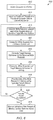
- FIG. 8 is a generalized flow diagram illustrating one embodiment of a method for flexibly exporting data in shader code.
- FIG. 9 is a generalized flow diagram illustrating one embodiment of a method for generating addresses for flexibly addressed memory requests.
- a system includes a processor, control unit, and memory subsystem.
- the processor launches a plurality of threads on the plurality of compute units, wherein each thread generates memory requests without specifying target memory addresses.
- the threads executing on the plurality of compute units convey a plurality of memory requests to the control unit.
- the control unit generates target memory addresses for the plurality of received memory requests.
- the memory requests are write requests, and the control unit interleaves write requests from the plurality of threads into a single output buffer stored in the memory.
- the control unit can be located in a cache, in a memory controller, or in another location within the system.
- computing system 100 includes system on chip (SoC) 105 coupled to memory 150 .
- SoC 105 can also be referred to as an integrated circuit (IC).
- SoC 105 includes processing units 175 A-N of central processing unit (CPU) 165 , input/output (I/O) interfaces 155 , caches 160 A-B, fabric 120 , graphics processing unit (GPU) 130 , local memory 110 , and memory controller(s) 140 .
- SoC 105 can also include other components not shown in FIG. 1 to avoid obscuring the figure.
- Processing units 175 A-N are representative of any number and type of processing units.
- processing units 175 A-N are CPU cores. In another embodiment, one or more of processing units 175 A-N are other types of processing units (e.g., application specific integrated circuit (ASIC), field programmable gate array (FPGA), digital signal processor (DSP)). Processing units 175 A-N of CPU 165 are coupled to caches 160 A-B and fabric 120 .
- ASIC application specific integrated circuit
- FPGA field programmable gate array
- DSP digital signal processor
- processing units 175 A-N are configured to execute instructions of a particular instruction set architecture (ISA). Each processing unit 175 A-N includes one or more execution units, cache memories, schedulers, branch prediction circuits, and so forth. In one embodiment, the processing units 175 A-N are configured to execute the main control software of system 100 , such as an operating system. Generally, software executed by processing units 175 A-N during use can control the other components of system 100 to realize the desired functionality of system 100 . Processing units 175 A-N can also execute other software, such as application programs.
- ISA instruction set architecture
- GPU 130 includes at least control unit 135 and compute units 145 A-N. It is noted that control unit 135 can also be located in other locations (e.g., fabric 120 , memory controller 140 ). Control unit 135 includes logic for generating target memory addresses for received write requests which do not include specified target memory addresses. In one embodiment, the memory addresses generated by control unit 135 target buffer 115 in local memory 110 . In other embodiments, the memory addresses generated by control unit 135 can target buffers in other locations (e.g., memory 150 ).
- Compute units 145 A-N are representative of any number and type of compute units that are used for graphics or general-purpose processing. Each compute unit 145 A-N includes any number of execution units, with the number of execution units per compute unit varying from embodiment to embodiment.
- GPU 130 is coupled to local memory 110 and fabric 120 .
- local memory 110 is implemented using high-bandwidth memory (HBM).
- HBM high-bandwidth memory
- the combination of local memory 110 and memory 150 can be referred to herein as a “memory subsystem”.
- either local memory 110 or memory 150 can be referred to herein as a “memory subsystem”.
- GPU 130 is configured to execute graphics pipeline operations such as draw commands, pixel operations, geometric computations, rasterization operations, and other operations for rendering an image to a display.
- GPU 130 is configured to execute operations unrelated to graphics.
- GPU 130 is configured to execute both graphics operations and non-graphics related operations.
- GPU 130 is configured to launch a plurality of threads on the plurality of compute units 145 A-N, wherein each thread generates memory requests without specifying target memory addresses.
- the plurality of compute units 145 A-N convey a plurality of memory requests to control unit 135 .
- Control unit 135 generates target memory addresses for the plurality of received memory requests.
- the memory requests are write requests, and control unit 135 interleaves write requests from the plurality of threads into buffer 115 stored in local memory 110 .
- I/O interfaces 155 are coupled to fabric 120 , and I/O interfaces 155 are representative of any number and type of interfaces (e.g., peripheral component interconnect (PCI) bus, PCI-Extended (PCI-X), PCIE (PCI Express) bus, gigabit Ethernet (GBE) bus, universal serial bus (USB)).
- PCI peripheral component interconnect
- PCI-X PCI-Extended
- PCIE PCI Express
- GEE gigabit Ethernet
- USB universal serial bus
- peripheral devices include (but are not limited to) displays, keyboards, mice, printers, scanners, joysticks or other types of game controllers, media recording devices, external storage devices, network interface cards, and so forth.
- SoC 105 is coupled to memory 150 , which includes one or more memory modules. Each of the memory modules includes one or more memory devices mounted thereon. In some embodiments, memory 150 includes one or more memory devices mounted on a motherboard or other carrier upon which SoC 105 is also mounted. In one embodiment, memory 150 is used to implement a random access memory (RAM) for use with SoC 105 during operation.
- RAM random access memory
- the RAM implemented can be static RAM (SRAM), dynamic RAM (DRAM), Resistive RAM (ReRAM), Phase Change RAM (PCRAM), or any other volatile or non-volatile RAM.
- the type of DRAM that is used to implement memory 150 includes (but is not limited to) double data rate (DDR) DRAM, DDR2 DRAM, DDR3 DRAM, and so forth.
- SoC 105 can also include one or more cache memories that are internal to the processing units 175 A-N and/or compute units 145 A-N.
- SoC 105 includes caches 160 A-B that are utilized by processing units 175 A-N.
- caches 160 A-B are part of a cache subsystem including a cache controller.
- the letter “N” when displayed herein next to various structures is meant to generically indicate any number of elements for that structure (e.g., any number of processing units 175 A-N in CPU 165 , including one processing unit). Additionally, different references within FIG. 1 that use the letter “N” (e.g., compute units 145 A-N) are not intended to indicate that equal numbers of the different elements are provided (e.g., the number of processing units 175 A-N in CPU 165 can differ from the number of compute units 145 A-N of GPU 130 ).
- computing system 100 can be a computer, laptop, mobile device, server or any of various other types of computing systems or devices. It is noted that the number of components of computing system 100 and/or SoC 105 can vary from embodiment to embodiment. There can be more or fewer of each component/subcomponent than the number shown in FIG. 1 . For example, in another embodiment, SoC 105 can include multiple memory controllers coupled to multiple memories. It is also noted that computing system 100 and/or SoC 105 can include other components not shown in FIG. 1 . Additionally, in other embodiments, computing system 100 and SoC 105 can be structured in other ways than shown in FIG. 1 .
- GPU 205 includes at least command processor 210 and compute units 215 A-N, 220 A-N, and 225 A-N.
- Compute units 215 A-N, 220 A-N, and 225 A-N are representative of any number of compute units which are included within GPU 205 .
- each compute unit can execute one thread, two threads, four threads, or other number of threads.
- command processor 210 is configured to issue threads for execution to the various compute units 215 A-N, 220 A-N, and 225 A-N.
- Each compute unit 215 A-N, 220 A-N, and 225 A-N is configured to execute flexibly-addressed memory requests that do not specify memory requests.
- the memory requests specify a buffer identifier (ID).
- the memory requests are conveyed to memory controller 240 on the path to memory 250 .
- control unit 245 is configured to generate an address for the memory request.
- control unit 245 accesses a base address for the buffer ID specified by the memory request. Then, control unit 245 determines an offset to apply to the base address.
- Control unit 245 is configured to receive the multiple memory requests from different compute units 215 A-N, 220 A-N, and 225 A-N and coordinate access to the single buffer specified by the buffer ID. In one embodiment, for write requests targeting the single buffer 260 , control unit 245 is configured to generate a linearly incrementing address for consecutive write requests regardless of the compute unit which generated the request. After control unit 245 generates a given address for a given write request, the given write request is conveyed to memory 250 and performed to the given address of buffer 260 .
- GPU 300 a block diagram of one embodiment of a graphics processing unit (GPU) 300 is shown.
- the logic of GPU 300 is included in GPU 130 (of FIG. 1 ).
- GPU 300 includes at least shader arrays 305 A-D, command center hub 320 , fabric 325 , and cache 330 .
- GPU 300 also includes other logic and/or other components which are not shown in FIG. 3 to avoid obscuring the figure.
- the structure of GPU 300 is merely one example of a structure which is used in one embodiment. In other embodiments, GPU 300 can be organized in other manners.
- Shader arrays 305 A-D are representative of any number and type of shader compute resources which are included in GPU 300 . Shader arrays 305 A-D can also be referred to as “shader units”. Each shader array 305 A-D includes a plurality of compute units which include various compute resources for performing geometry, vertex, pixel, and/or other shading operations to render graphics. In various embodiments, the compute resources include components for fetching and decoding instructions, one or more arithmetic logic units “ALUs” for performing arithmetic calculations, and other resources. Although not shown in FIG. 3 , each shader array 305 A-D can include a level one (L1) cache.
- L1 cache level one
- shader array 305 A includes compute units 310 A-N.
- Compute units 310 A-N are representative of any number of compute units, with the number of compute units varying from embodiment to embodiment.
- the other shader arrays 305 B-D can also include a plurality of compute units as is shown for shader array 305 .
- Shader arrays 305 A-D are coupled to cache 330 via fabric 325 .
- cache 330 is a level two (L2) cache. Depending on the embodiment, cache 330 is coupled to a memory (not shown) or another level of cache (not shown).
- Command center hub 320 is representative of any number and type of command processors, schedulers, and other command processing resources.
- control unit 335 is located within cache 330 . In another embodiment, control unit 335 is located within fabric 325 . In one embodiment, control unit 335 is configured to receive write requests generated by the compute units of shader arrays 305 A-D, wherein the write requests do not specify an address. Control unit 335 generates explicit addresses for these write requests, with the generated addresses targeting locations in buffer 340 . In one embodiment, control unit 335 generates linearly increasing memory addresses for the write requests which are received from the multiple shader arrays 305 A-D.
- FIG. 4 a block diagram of one embodiment of a hardware control unit 400 is shown.
- the logic of hardware control unit 400 can be included within control unit 135 (of FIG. 1 ), control unit 245 (of FIG. 2 ), and/or control unit 335 (of FIG. 3 ).
- Hardware control unit 400 includes queue 405 , picker 410 , register 415 , counter 420 , and address generation unit 430 .
- Queue 405 stores incoming memory requests generated by a plurality of threads. The memory requests which are generated by the plurality of threads do not specify target memory addresses.
- Queue 405 is representative of any number and type of queue or buffer for storing incoming memory requests. While a single queue 405 is shown in FIG. 4 , in other embodiments, hardware control unit 400 can include multiple queues for storing incoming memory requests.
- queue 405 is a first-in, first-out queue. In other embodiments, queue 405 can be other types of queues.
- Picker 410 is configured to select a request within the entries of queue 405 for conveying to address generation unit 430 . In one embodiment, picker 410 selects the oldest request in queue 405 . In one embodiment, address generation unit 430 is configured to retrieve the value from register 415 . In one embodiment, register 415 stores a buffer start address. In one embodiment, register 415 is programmable by software. The buffer start address stored in register 415 indicates the first address of the buffer where the data of the incoming write requests will be stored in memory. In one embodiment, address generation unit 430 is configured to add the offset 425 generated by counter 420 to the buffer start address retrieved from register 415 . The sum of offset 425 and the buffer start address is used to generate an address to apply to the next write request.
- Shader pseudo code 505 is shown at the top of FIG. 5 as one example of shader code which can be utilized to rasterize primitives.
- Shader pseudo code 505 shows an example of code for rasterizing small primitives (e.g., pixel-sized triangles) using a GPU.
- Code 505 computes the lit pixels of the primitive and then stores color values and coordinates of these lit pixels in a buffer. The buffer address offset is derived according to the pixel coordinates (x,y).
- buffer 510 A is initialized, with the size of buffer 510 A determined by the render target resolution. Then, a plurality of threads 515 A-N are launched to rasterize primitives, with each thread rasterizing a different primitive. Threads 515 A-N are representative of any number of threads which are launched. Accordingly, it should be understood that while four threads 515 A-N are shown in FIG. 5 , this is merely for illustrative purposes and any number of threads (other than four) can be launched in a given embodiment.
- Buffer 510 B is intended to represent buffer 510 A at a later point in time, after the threads 515 A-N have written the rasterized pixel data to buffer 510 B.
- the rasterized pixel data is not packed efficiently in buffer 510 B. Rather, there are several gaps of unused memory locations in buffer 510 B based on the unknown number of rasterized pixels created by each thread 515 A-N.
- Shader pseudo code 605 includes an example of code for rasterizing a plurality of primitives.
- the shader input is the vertex buffer, which stores (x,y,z) coordinates for each vertex of the primitive.
- the (x,y,z) coordinates are stored in single-precision floating-point format.
- the shader uses a rasterization algorithm to determine which pixels should be lit. Then, the shader exports the lit pixels to the output buffer without specifying the addresses of where the lit pixels should be written.
- each pixel includes a pointer to the location of the original primitive in the vertex buffer and a one-bit indicator. The indicator specifies whether the pixel is the last pixel of the primitive. In other embodiments, other formats for storing the pixel data are possible and are contemplated.
- other operators or instructions can be used in a programming language to specify arbitrary export.
- the instruction set architecture will include support for the new instruction(s) either via new instructions in the ISA or existing ISA instructions, with the new instruction enabling the arbitrary export of data to an output buffer.
- the compiler will discard or ignore the address specified in the high level language for a traditional memory request, and the compiler will translate the traditional memory request into a binary opcode which implements a memory request without specifying the target address.
- Buffer 610 A is initialized prior to shader pseudo code 605 being executed.
- the size of buffer 610 A is determined by the number of threads.
- a plurality of threads 615 A-N are launched for rasterizing a plurality of primitives.
- the number of threads 615 A-N which are launched can vary from embodiment to embodiment.
- the coordinates of rasterized pixels produced by the threads 615 A-N are conveyed to a hardware control unit (e.g., control unit 135 of FIG. 1 ) without specifying target memory addresses.
- the hardware control unit generates memory addresses for the write requests generated by threads 615 A-N.
- Buffer 610 B is intended to represent buffer 610 A at a later point in time after the pixel data has been exported.
- the pixel data from the write requests is written to consecutive addresses in buffer 610 B, allowing buffer 610 B to be used in an efficient manner.
- the hardware control unit generates linearly increasing memory addresses for write requests in the order in which the write requests are received from threads 615 A-N.
- pseudo shader code 705 is executed to export valid data to a linear buffer 710 A.
- Buffer 710 A is initialized and the size of buffer 710 A is determined by the number of threads.
- Pseudo shader code 705 is one example of code that is executed to export valid data to a linear buffer, which is widely used in many applications. The shader can perform various calculations on the input data and then the shader writes valid results to the output buffer. In this example, only thread 715 B does not have valid data while the other threads 715 A and 715 C-N have valid data.
- the compute units do not calculate the memory address for each thread 715 A-N. Rather, the compute units send each thread's write request with the buffer ID, without specifying a memory address, to a hardware control unit. Based on the buffer ID, the hardware control unit is able to determine the memory starting address of the specified buffer. Then, the hardware control unit derives the memory address offset for each request, and then the memory address offset is added to the memory starting address to calculate the final target memory address. The hardware control unit supplies the final target memory address to the memory interface module. As a result, the output buffer 710 B has all of the valid data packed together without any intervening gaps. Buffer 710 B is intended to represent buffer 710 A after the data generated by threads 715 A-N has been written to buffer 710 B.
- FIG. 8 one embodiment of a method 800 for flexibly exporting data in shader code is shown.
- the steps in this embodiment and those of FIG. 9 are shown in sequential order. However, it is noted that in various embodiments of the described methods, one or more of the elements described are performed concurrently, in a different order than shown, or are omitted entirely. Other additional elements are also performed as desired. Any of the various systems or apparatuses described herein are configured to implement method 800 .
- a computing system (e.g., system 100 of FIG. 1 ) initiates execution of a kernel (block 805 ).
- the computing system initiates the execution of the kernel on a GPU.
- the kernel is executed on any of various other types of processors (e.g., FPGA, ASIC, DSP).
- the computing system launches a plurality of threads on a plurality of compute units to execute the kernel (block 810 ).
- a kernel is defined as a function which is launched and executed by a plurality of threads.
- each thread executes the kernel using a unique thread identifier (ID).
- ID unique thread identifier
- each thread is launched on a separate compute unit.
- the term “thread” is defined as a sequence of programmed instructions that are managed independently by a scheduler. Also, the term “thread” is defined as an execution context which includes the information a processing unit needs to execute a stream of instructions. The execution context consists of the values of the processing unit's registers.
- the threads generate write requests, wherein each write request does not specify a target memory address (block 815 ). Then, the write requests without specified target memory addresses are conveyed to a hardware control unit (block 820 ).
- the hardware control unit is located in a cache. In another embodiment, the hardware control unit is located in a memory controller. In other embodiments, the hardware control unit can reside in other locations.
- the hardware control unit generates target memory addresses for the received write requests (block 825 ). In one embodiment, the hardware control unit increments the generated target memory address for every received write request. In other embodiments, the hardware control unit can utilize other techniques for generating the target memory address for received write requests. Then, the hardware control unit conveys the write requests and the target memory addresses to memory (block 830 ). Next, the data of the write requests is written to memory at the specified target memory addresses (block 835 ). If execution of the kernel has completed (conditional block 840 , “yes” leg), then the hardware control unit stores an indication of the amount of memory used to store the kernel data (block 845 ). It is noted that the amount of memory used to store the kernel data can also be referred to as the “final buffer size”.
- the final buffer size can be communicated to a driver or to the application which can potentially benefit the read operations performed in the next phase.
- method 800 ends. If the kernel has not completed (conditional block 840 , “no” leg), then method 800 returns to block 815 .
- a plurality of threads executing on a plurality of compute units generate flexibly addressed memory requests (block 905 ).
- the memory requests can include write requests or read requests.
- the memory requests include write requests for threads rasterizing a plurality of primitives.
- the memory requests include read requests reading the buffer of pixel data generated by the rasterization threads.
- the memory requests can include other types of write and/or read requests generated for other types of scenarios.
- the flexibly addressed memory requests are conveyed to a hardware control unit (block 910 ).
- the hardware control unit can be located in a cache, in a memory controller, or in other locations within a computing system. Examples of hardware control units are shown in FIGS. 1-4 .
- the hardware control unit is configured to determine a starting address for a buffer which is being targeted by the received memory requests (block 915 ). In one embodiment, the hardware control unit retrieves the buffer starting address from a programmable register. Then, the hardware control unit initializes a pointer to point to the starting address of the buffer (block 920 ). Next, the hardware control unit receives a given memory request (block 925 ). Then, the hardware control unit performs the given memory request to an address referenced by the pointer (block 930 ). In one embodiment, the hardware control unit writes data of a write request to a cache/memory location addressed by the pointer. In another embodiment, the hardware control unit reads data from a cache/memory location addressed by the pointer.
- the hardware control unit increments the pointer (block 935 ). If the threads have completed (conditional block 935 , “yes” leg), then method 900 ends. If the threads have not completed (conditional block 935 , “no” leg), then method 900 returns to block 925 .
- program instructions of a software application are used to implement the methods and/or mechanisms previously described.
- the program instructions describe the behavior of hardware in a high-level programming language, such as C.
- a hardware design language HDL
- the program instructions are stored on a non-transitory computer readable storage medium. Numerous types of storage media are available.
- the storage medium is accessible by a computing system during use to provide the program instructions and accompanying data to the computing system for program execution.
- the computing system includes at least one or more memories and one or more processors configured to execute program instructions.
Landscapes
- Engineering & Computer Science (AREA)
- Theoretical Computer Science (AREA)
- Software Systems (AREA)
- Physics & Mathematics (AREA)
- General Physics & Mathematics (AREA)
- General Engineering & Computer Science (AREA)
- Multimedia (AREA)
- Computer Graphics (AREA)
- Image Generation (AREA)
- Memory System Of A Hierarchy Structure (AREA)
Abstract
Description
Claims (20)
Applications Claiming Priority (3)
| Application Number | Priority Date | Filing Date | Title |
|---|---|---|---|
| CN201710297286.8A CN108804219B (en) | 2017-04-28 | 2017-04-28 | Flexible shader export design in multiple compute cores |
| CN201710297286 | 2017-04-28 | ||
| CN201710297286.8 | 2017-04-28 |
Publications (2)
| Publication Number | Publication Date |
|---|---|
| US20180314528A1 US20180314528A1 (en) | 2018-11-01 |
| US10606740B2 true US10606740B2 (en) | 2020-03-31 |
Family
ID=63916629
Family Applications (1)
| Application Number | Title | Priority Date | Filing Date |
|---|---|---|---|
| US15/607,118 Active 2037-11-28 US10606740B2 (en) | 2017-04-28 | 2017-05-26 | Flexible shader export design in multiple computing cores |
Country Status (2)
| Country | Link |
|---|---|
| US (1) | US10606740B2 (en) |
| CN (1) | CN108804219B (en) |
Cited By (1)
| Publication number | Priority date | Publication date | Assignee | Title |
|---|---|---|---|---|
| US12499604B2 (en) | 2021-12-27 | 2025-12-16 | Advanced Micro Devices, Inc. | Updating shader scheduling policy at runtime |
Families Citing this family (5)
| Publication number | Priority date | Publication date | Assignee | Title |
|---|---|---|---|---|
| KR20180038793A (en) * | 2016-10-07 | 2018-04-17 | 삼성전자주식회사 | Method and apparatus for processing image data |
| US10535178B2 (en) | 2016-12-22 | 2020-01-14 | Advanced Micro Devices, Inc. | Shader writes to compressed resources |
| CN114721584B (en) * | 2021-01-06 | 2025-07-18 | 伊姆西Ip控股有限责任公司 | Method, apparatus and computer program product for writing data |
| TWI835178B (en) * | 2022-06-24 | 2024-03-11 | 新唐科技股份有限公司 | Continuous memory access acceleration circuit, address shift circuit and address generation method |
| CN118247128A (en) * | 2024-04-12 | 2024-06-25 | 摩尔线程智能科技(北京)有限责任公司 | Shader operation data acquisition method, device, system, medium and processor |
Citations (23)
| Publication number | Priority date | Publication date | Assignee | Title |
|---|---|---|---|---|
| US6108460A (en) | 1996-01-02 | 2000-08-22 | Pixelfusion Limited | Load balanced image generation |
| US6243081B1 (en) | 1998-07-31 | 2001-06-05 | Hewlett-Packard Company | Data structure for efficient retrieval of compressed texture data from a memory system |
| US6452602B1 (en) | 1999-12-13 | 2002-09-17 | Ati International Srl | Method and apparatus for storing compressed data |
| US6959110B1 (en) | 2000-08-17 | 2005-10-25 | Nvidia Corporation | Multi-mode texture compression algorithm |
| US7042462B2 (en) * | 2003-01-29 | 2006-05-09 | Samsung Electronics Co., Ltd. | Pixel cache, 3D graphics accelerator using the same, and method therefor |
| US20070011432A1 (en) * | 2005-07-06 | 2007-01-11 | Advanced Micro Devices, Inc. | Address generation unit with operand recycling |
| US7239322B2 (en) * | 2003-09-29 | 2007-07-03 | Ati Technologies Inc | Multi-thread graphic processing system |
| US20090189909A1 (en) | 2008-01-25 | 2009-07-30 | Via Technologies, Inc. | Graphics Processor having Unified Cache System |
| US7719540B2 (en) * | 2004-03-31 | 2010-05-18 | Intel Corporation | Render-cache controller for multithreading, multi-core graphics processor |
| US8174534B2 (en) * | 2007-12-06 | 2012-05-08 | Via Technologies, Inc. | Shader processing systems and methods |
| US8295621B1 (en) | 2007-12-13 | 2012-10-23 | Nvidia Corporation | Data decompression using a geometry shading unit |
| US20120320067A1 (en) | 2011-06-17 | 2012-12-20 | Konstantine Iourcha | Real time on-chip texture decompression using shader processors |
| US8643659B1 (en) | 2003-12-31 | 2014-02-04 | 3Dlabs Inc., Ltd. | Shader with global and instruction caches |
| US20150026438A1 (en) | 2013-07-18 | 2015-01-22 | Nvidia Corporation | System, method, and computer program product for cooperative multi-threading for vector threads |
| US20150070380A1 (en) | 2013-09-11 | 2015-03-12 | Nvidia Corporation | System, method, and computer program product for using compression with programmable sample locations |
| US20150070381A1 (en) | 2013-09-11 | 2015-03-12 | Nvidia Corporation | System, method, and computer program product for using compression with programmable sample locations |
| US20170186224A1 (en) | 2007-07-31 | 2017-06-29 | Nvidia Corporation | Using a Geometry Shader for Variable Input and Output Algorithms |
| US20170256025A1 (en) | 2016-03-04 | 2017-09-07 | Samsung Electronics Co., Ltd. | Efficient low-power texture cache architecture |
| US20170278215A1 (en) | 2016-03-28 | 2017-09-28 | Intel Corporation | Method and Apparatus for Multi Format Lossless Compression |
| US20170287209A1 (en) | 2016-03-29 | 2017-10-05 | Intel Corporation | Per-Sample MSAA Rendering Using Comprehension Data |
| US9819970B2 (en) | 2007-06-30 | 2017-11-14 | Microsoft Technology Licensing, Llc | Reducing memory consumption during video decoding |
| US20180089091A1 (en) | 2016-09-26 | 2018-03-29 | Intel Corporation | Cache and compression interoperability in a graphics processor pipeline |
| US20180182155A1 (en) | 2016-12-22 | 2018-06-28 | Advanced Micro Devices, Inc. | Shader writes to compressed resources |
-
2017
- 2017-04-28 CN CN201710297286.8A patent/CN108804219B/en active Active
- 2017-05-26 US US15/607,118 patent/US10606740B2/en active Active
Patent Citations (25)
| Publication number | Priority date | Publication date | Assignee | Title |
|---|---|---|---|---|
| US6108460A (en) | 1996-01-02 | 2000-08-22 | Pixelfusion Limited | Load balanced image generation |
| US6243081B1 (en) | 1998-07-31 | 2001-06-05 | Hewlett-Packard Company | Data structure for efficient retrieval of compressed texture data from a memory system |
| US6452602B1 (en) | 1999-12-13 | 2002-09-17 | Ati International Srl | Method and apparatus for storing compressed data |
| US6959110B1 (en) | 2000-08-17 | 2005-10-25 | Nvidia Corporation | Multi-mode texture compression algorithm |
| US7042462B2 (en) * | 2003-01-29 | 2006-05-09 | Samsung Electronics Co., Ltd. | Pixel cache, 3D graphics accelerator using the same, and method therefor |
| US7239322B2 (en) * | 2003-09-29 | 2007-07-03 | Ati Technologies Inc | Multi-thread graphic processing system |
| US8643659B1 (en) | 2003-12-31 | 2014-02-04 | 3Dlabs Inc., Ltd. | Shader with global and instruction caches |
| US7719540B2 (en) * | 2004-03-31 | 2010-05-18 | Intel Corporation | Render-cache controller for multithreading, multi-core graphics processor |
| US20070011432A1 (en) * | 2005-07-06 | 2007-01-11 | Advanced Micro Devices, Inc. | Address generation unit with operand recycling |
| US9819970B2 (en) | 2007-06-30 | 2017-11-14 | Microsoft Technology Licensing, Llc | Reducing memory consumption during video decoding |
| US20170186224A1 (en) | 2007-07-31 | 2017-06-29 | Nvidia Corporation | Using a Geometry Shader for Variable Input and Output Algorithms |
| US8174534B2 (en) * | 2007-12-06 | 2012-05-08 | Via Technologies, Inc. | Shader processing systems and methods |
| US8295621B1 (en) | 2007-12-13 | 2012-10-23 | Nvidia Corporation | Data decompression using a geometry shading unit |
| US20090189909A1 (en) | 2008-01-25 | 2009-07-30 | Via Technologies, Inc. | Graphics Processor having Unified Cache System |
| US20120320067A1 (en) | 2011-06-17 | 2012-12-20 | Konstantine Iourcha | Real time on-chip texture decompression using shader processors |
| US20160300320A1 (en) | 2011-06-17 | 2016-10-13 | Advanced Micro Devices, Inc. | Real time on-chip texture decompression using shader processors |
| US20150026438A1 (en) | 2013-07-18 | 2015-01-22 | Nvidia Corporation | System, method, and computer program product for cooperative multi-threading for vector threads |
| US20150070381A1 (en) | 2013-09-11 | 2015-03-12 | Nvidia Corporation | System, method, and computer program product for using compression with programmable sample locations |
| US20150070380A1 (en) | 2013-09-11 | 2015-03-12 | Nvidia Corporation | System, method, and computer program product for using compression with programmable sample locations |
| US20170256025A1 (en) | 2016-03-04 | 2017-09-07 | Samsung Electronics Co., Ltd. | Efficient low-power texture cache architecture |
| US20170256024A1 (en) | 2016-03-04 | 2017-09-07 | Samsung Electronics Co., Ltd. | Cache architecture for efficiently accessing texture data using buffers |
| US20170278215A1 (en) | 2016-03-28 | 2017-09-28 | Intel Corporation | Method and Apparatus for Multi Format Lossless Compression |
| US20170287209A1 (en) | 2016-03-29 | 2017-10-05 | Intel Corporation | Per-Sample MSAA Rendering Using Comprehension Data |
| US20180089091A1 (en) | 2016-09-26 | 2018-03-29 | Intel Corporation | Cache and compression interoperability in a graphics processor pipeline |
| US20180182155A1 (en) | 2016-12-22 | 2018-06-28 | Advanced Micro Devices, Inc. | Shader writes to compressed resources |
Non-Patent Citations (10)
| Title |
|---|
| Akenine-Möller, et al., "Graphics Processing Units for Handhelds", Proceedings of the IEEE, May 2008, pp. 779-789, vol. 96, Issue 5, IEEE, New York, NY, USA. |
| Communication pursuant to Article 94(3) EPC in European Application No. 17150171.1, dated Jan. 15, 2018, 4 pages. |
| Communication pursuant to Article 94(3) EPC in European Application No. 17150171.1, dated Jul. 25, 2018, 3 pages. |
| European Search Report in European Application No. 17150171.1, dated Jul. 26, 2017, 4 pages. |
| Final Office Action in U.S. Appl. No. 15/389,075, dated Sep. 19, 2018, 14 pages. |
| International Search Report and Written Opinion in International Application No. PCT/US2012/042442, dated Oct. 31, 2012, 11 pages. |
| International Search Report and Written Opinion in International Application No. PCT/US2017/067697, dated Mar. 20, 2018, 10 pages. |
| Non-Final Office Action in U.S. Appl. No. 15/389,075, dated Apr. 11, 2019, 16 pages. |
| Non-Final Office Action in U.S. Appl. No. 15/389,075, dated Apr. 23, 2018, 13 pages. |
| Woo et al., "A 195mW, 9.1 MVertices/s Fully Programmable 3-D Graphics Processor for Low-Power Mobile Devices", IEEE Journal of Solid-State Circuits, Nov. 19, 2008, pp. 2370-2380, vol. 43, No. 11, IEEE, Piscataway, NJ, USA. |
Cited By (1)
| Publication number | Priority date | Publication date | Assignee | Title |
|---|---|---|---|---|
| US12499604B2 (en) | 2021-12-27 | 2025-12-16 | Advanced Micro Devices, Inc. | Updating shader scheduling policy at runtime |
Also Published As
| Publication number | Publication date |
|---|---|
| CN108804219B (en) | 2024-01-12 |
| US20180314528A1 (en) | 2018-11-01 |
| CN108804219A (en) | 2018-11-13 |
Similar Documents
| Publication | Publication Date | Title |
|---|---|---|
| US10606740B2 (en) | Flexible shader export design in multiple computing cores | |
| EP2936492B1 (en) | Multi-mode memory access techniques for performing graphics processing unit-based memory transfer operations | |
| US8817031B2 (en) | Distributed stream output in a parallel processing unit | |
| JP4799588B2 (en) | Extrapolation of non-resident mipmap data using resident mipmap data | |
| US10269090B2 (en) | Rendering to multi-resolution hierarchies | |
| CN102648449B (en) | A kind of method for the treatment of interference incident and Graphics Processing Unit | |
| US8692829B2 (en) | Calculation of plane equations after determination of Z-buffer visibility | |
| US8542247B1 (en) | Cull before vertex attribute fetch and vertex lighting | |
| KR102474237B1 (en) | Write Shaders to Compressed Resources | |
| US12229215B2 (en) | Performing matrix multiplication in a streaming processor | |
| US8810592B2 (en) | Vertex attribute buffer for inline immediate attributes and constants | |
| CN110008009A (en) | Bind constant at runtime to improve resource utilization | |
| US10474468B2 (en) | Indicating instruction scheduling mode for processing wavefront portions | |
| US20080204451A1 (en) | Geometry processor using a post-vertex cache and method thereof | |
| CN103810743A (en) | Setting downstream render state in an upstream shader | |
| US8564616B1 (en) | Cull before vertex attribute fetch and vertex lighting | |
| US20030142105A1 (en) | Optimized packing of loose data in a graphics queue | |
| US9594599B1 (en) | Method and system for distributing work batches to processing units based on a number of enabled streaming multiprocessors | |
| US8427493B2 (en) | Draw commands with built-in begin/end | |
| US9013498B1 (en) | Determining a working set of texture maps | |
| US8947444B1 (en) | Distributed vertex attribute fetch | |
| JP2025501026A (en) | Graphics Discard Engine | |
| US9916680B2 (en) | Low-power processing in depth read-only operating regimes | |
| US9406101B2 (en) | Technique for improving the performance of a tessellation pipeline | |
| US8704835B1 (en) | Distributed clip, cull, viewport transform and perspective correction |
Legal Events
| Date | Code | Title | Description |
|---|---|---|---|
| AS | Assignment |
Owner name: ADVANCED MICRO DEVICES, INC., CALIFORNIA Free format text: ASSIGNMENT OF ASSIGNORS INTEREST;ASSIGNOR:ZHU, YUNPENG;REEL/FRAME:042519/0491 Effective date: 20170522 Owner name: ATI TECHNOLOGIES ULC, CANADA Free format text: ASSIGNMENT OF ASSIGNORS INTEREST;ASSIGNOR:MIRZA, JIMSHED;REEL/FRAME:042519/0567 Effective date: 20170526 |
|
| STPP | Information on status: patent application and granting procedure in general |
Free format text: NON FINAL ACTION MAILED |
|
| STPP | Information on status: patent application and granting procedure in general |
Free format text: RESPONSE TO NON-FINAL OFFICE ACTION ENTERED AND FORWARDED TO EXAMINER |
|
| STPP | Information on status: patent application and granting procedure in general |
Free format text: FINAL REJECTION MAILED |
|
| STPP | Information on status: patent application and granting procedure in general |
Free format text: RESPONSE AFTER FINAL ACTION FORWARDED TO EXAMINER |
|
| STPP | Information on status: patent application and granting procedure in general |
Free format text: NOTICE OF ALLOWANCE MAILED -- APPLICATION RECEIVED IN OFFICE OF PUBLICATIONS |
|
| STPP | Information on status: patent application and granting procedure in general |
Free format text: PUBLICATIONS -- ISSUE FEE PAYMENT RECEIVED |
|
| STPP | Information on status: patent application and granting procedure in general |
Free format text: PUBLICATIONS -- ISSUE FEE PAYMENT VERIFIED |
|
| STCF | Information on status: patent grant |
Free format text: PATENTED CASE |
|
| CC | Certificate of correction | ||
| MAFP | Maintenance fee payment |
Free format text: PAYMENT OF MAINTENANCE FEE, 4TH YEAR, LARGE ENTITY (ORIGINAL EVENT CODE: M1551); ENTITY STATUS OF PATENT OWNER: LARGE ENTITY Year of fee payment: 4 |