US10602997B2 - Radiographing apparatus and radiographing system - Google Patents
Radiographing apparatus and radiographing system Download PDFInfo
- Publication number
- US10602997B2 US10602997B2 US15/494,295 US201715494295A US10602997B2 US 10602997 B2 US10602997 B2 US 10602997B2 US 201715494295 A US201715494295 A US 201715494295A US 10602997 B2 US10602997 B2 US 10602997B2
- Authority
- US
- United States
- Prior art keywords
- casing
- radiographing apparatus
- level
- radiation
- incidence
- Prior art date
- Legal status (The legal status is an assumption and is not a legal conclusion. Google has not performed a legal analysis and makes no representation as to the accuracy of the status listed.)
- Active, expires
Links
Images


Classifications
-
- A—HUMAN NECESSITIES
- A61—MEDICAL OR VETERINARY SCIENCE; HYGIENE
- A61B—DIAGNOSIS; SURGERY; IDENTIFICATION
- A61B6/00—Apparatus or devices for radiation diagnosis; Apparatus or devices for radiation diagnosis combined with radiation therapy equipment
- A61B6/42—Arrangements for detecting radiation specially adapted for radiation diagnosis
- A61B6/4283—Arrangements for detecting radiation specially adapted for radiation diagnosis characterised by a detector unit being housed in a cassette
-
- A—HUMAN NECESSITIES
- A61—MEDICAL OR VETERINARY SCIENCE; HYGIENE
- A61B—DIAGNOSIS; SURGERY; IDENTIFICATION
- A61B6/00—Apparatus or devices for radiation diagnosis; Apparatus or devices for radiation diagnosis combined with radiation therapy equipment
- A61B6/10—Safety means specially adapted therefor
- A61B6/102—Protection against mechanical damage, e.g. anti-collision devices
-
- A—HUMAN NECESSITIES
- A61—MEDICAL OR VETERINARY SCIENCE; HYGIENE
- A61B—DIAGNOSIS; SURGERY; IDENTIFICATION
- A61B6/00—Apparatus or devices for radiation diagnosis; Apparatus or devices for radiation diagnosis combined with radiation therapy equipment
- A61B6/42—Arrangements for detecting radiation specially adapted for radiation diagnosis
- A61B6/4208—Arrangements for detecting radiation specially adapted for radiation diagnosis characterised by using a particular type of detector
- A61B6/4216—Arrangements for detecting radiation specially adapted for radiation diagnosis characterised by using a particular type of detector using storage phosphor screens
-
- G—PHYSICS
- G01—MEASURING; TESTING
- G01T—MEASUREMENT OF NUCLEAR OR X-RADIATION
- G01T7/00—Details of radiation-measuring instruments
-
- G—PHYSICS
- G03—PHOTOGRAPHY; CINEMATOGRAPHY; ANALOGOUS TECHNIQUES USING WAVES OTHER THAN OPTICAL WAVES; ELECTROGRAPHY; HOLOGRAPHY
- G03B—APPARATUS OR ARRANGEMENTS FOR TAKING PHOTOGRAPHS OR FOR PROJECTING OR VIEWING THEM; APPARATUS OR ARRANGEMENTS EMPLOYING ANALOGOUS TECHNIQUES USING WAVES OTHER THAN OPTICAL WAVES; ACCESSORIES THEREFOR
- G03B42/00—Obtaining records using waves other than optical waves; Visualisation of such records by using optical means
- G03B42/02—Obtaining records using waves other than optical waves; Visualisation of such records by using optical means using X-rays
- G03B42/04—Holders for X-ray films
-
- H—ELECTRICITY
- H02—GENERATION; CONVERSION OR DISTRIBUTION OF ELECTRIC POWER
- H02J—ELECTRIC POWER NETWORKS; CIRCUIT ARRANGEMENTS OR SYSTEMS FOR SUPPLYING OR DISTRIBUTING ELECTRIC POWER; SYSTEMS FOR STORING ELECTRIC ENERGY
- H02J7/00—Circuit arrangements for charging or discharging batteries or for supplying loads from batteries
-
- H02J7/0044—
-
- H02J7/0052—
-
- H—ELECTRICITY
- H02—GENERATION; CONVERSION OR DISTRIBUTION OF ELECTRIC POWER
- H02J—ELECTRIC POWER NETWORKS; CIRCUIT ARRANGEMENTS OR SYSTEMS FOR SUPPLYING OR DISTRIBUTING ELECTRIC POWER; SYSTEMS FOR STORING ELECTRIC ENERGY
- H02J7/00—Circuit arrangements for charging or discharging batteries or for supplying loads from batteries
- H02J7/70—Circuit arrangements for charging or discharging batteries or for supplying loads from batteries characterised by the mechanical construction
- H02J7/731—Circuit arrangements for charging or discharging batteries or for supplying loads from batteries characterised by the mechanical construction specially adapted for holding portable devices containing batteries
Definitions
- the present disclosure relates to a radiographing apparatus including a radiation detection panel and a radiographing system including the radiographing apparatus.
- Radiographing apparatuses that detect intensity distribution of radiation that has passed through an object to acquire a radiographic image are generally widely used in non-destructive inspection for industrial use and medical diagnostics.
- Radiographing apparatuses take radiographs in a state in which the irradiation area of radiation emitted from a radiation source, the effective image-acquisition area of the radiographing apparatus, and the position of the object to be radiographed are aligned. For the purpose of alignment, an operator needs to easily recognize the effective image-acquisition area of the radiographing apparatus.
- Japanese Patent No. 4617017 discloses a radiographing apparatus in which indicators with different level-difference or different frictional resistances are provided on the side surface of the casing to allow tactile recognition of the effective image-acquisition area of the radiographing apparatus.
- the radiographing apparatus disclosed in Japanese Patent No. 4617017 may not take sufficient measures for protecting the casing during handling. For example, while aligning the radiographing apparatus, a level-difference portion formed as an indicator could be caught on a bed or table for radiographing and damage the casing.
- the present disclosure provides a radiographing apparatus with a level-difference portion indicating an effective image-acquisition area, in which an external impact to the level-difference portion is reduced or eliminated.
- a radiographing apparatus includes a radiation detection panel including an effective image-acquisition area configured to detect radiation and a casing configured to house the radiation detection panel.
- the casing includes an incidence surface on which the radiation is incident, a back surface opposite the incidence surface, and a side surface between the incidence surface and the back surface.
- a level-difference portion indicating a position based on the effective image-acquisition area and a protrusion protruding more outward than the level-difference portion are provided.
- FIG. 1A is an external view of a radiographing apparatus of a first embodiment.
- FIG. 1B is a partial enlarged view of the radiographing apparatus in FIG. 1A .
- FIG. 2A is a cross-sectional view taken along line IIA-IIA in FIG. 1A .
- FIG. 2B is a cross-sectional view taken along line IIB-IIB in FIG. 1A .
- FIG. 3A is an external view of the radiographing apparatus of the first embodiment.
- FIG. 3B is a partial enlarged view of the radiographing apparatus in FIG. 3A .
- FIG. 4A is an external view of the radiographing apparatus of the first embodiment.
- FIG. 4B is a partial enlarged view of the radiographing apparatus in FIG. 4A .
- FIG. 5A is an external view of the radiographing apparatus of the first embodiment.
- FIG. 5B is a partial enlarged view of the radiographing apparatus in FIG. 5A .
- FIG. 6A is an external view of a radiographing apparatus of a second embodiment.
- FIG. 6B is a partial enlarge view of the radiographing apparatus in FIG. 6A .
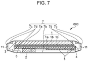
- FIG. 7 is a cross-sectional view taken along line VII-VII in FIG. 6A .
- FIG. 8A is an external view of an application of a radiographing apparatus of an embodiment.
- FIG. 8B is a diagram illustrating a state in which the radiographing apparatus is housed in a battery charger.
- radiation includes not only X-rays but also ⁇ -rays, ⁇ -rays, ⁇ -rays, corpuscular rays, and cosmic rays.
- a radiographing apparatus according to a first embodiment will be described with reference to FIGS. 1A and 1B to FIGS. 5A and 5B .
- FIG. 1A is an external view of the radiographing apparatus of the first embodiment.
- FIG. 1B is an enlarged view of the periphery of part a of the radiographing apparatus in FIG. 1A .
- FIGS. 2A and 2B are cross-sectional views of the radiographing apparatus of the first embodiment.
- FIG. 2A is a cross-sectional view taken along line IIA-IIA in FIG. 1A .
- FIG. 2B is a cross-sectional view taken along line IIB-IIB in FIG. 1A .
- a radiographing apparatus 100 acquires a radiographic image according to radiation radiated by a radiation generating apparatus (not shown) and transmitted through an object.
- the radiographing apparatus 100 transfers the acquired radiographic image to an external unit (a console).
- the transferred radiographic image is displayed on a display unit or the like, and the quality is checked by the user.
- the radiographing apparatus 100 includes a radiation detection panel 1 for converting radiation to an electrical signal.
- the radiation detection panel 1 has the function of converting the incident radiation to an electrical signal.
- the radiation detection panel 1 includes a sensor substrate 1 c in which a plurality of photoelectric conversion elements are disposed in two dimensions on a glass substrate, a phosphor layer 1 a disposed on the sensor substrate 1 c , and a phosphor protection film 1 b disposed on the phosphor layer 1 a .
- the plurality of photoelectric conversion elements disposed on the sensor substrate 1 c are PIN-type or MIS-type conversion elements capable of detecting visible light.
- the phosphor protection film 1 b is made of a material with relatively high moisture resistance and is used to protect the phosphor layer 1 a .
- the radiation detection panel 1 has an effective image-acquisition area in which incident radiation can be imaged as a radiographic image.
- the whole or part of an area on a surface on which the plurality of photoelectric conversion elements are disposed is defined as the effective image-acquisition area.
- the phosphor layer 1 a emits light by the incident radiation, and the photoelectric conversion elements disposed on the sensor substrate 1 c convert the emitted light to an electrical signal.
- the radiation detection panel 1 may include direct conversion type conversion elements that directly convert radiation to an electrical signal instead of the phosphor layer 1 a and the photoelectric conversion elements.
- the radiation detection panel 1 is electrically connected to a control substrate 5 via a flexible circuit board 4 .
- the control substrate 5 reads the resultant electrical signal from the radiation detection panel 1 and processes the read electrical signal.
- the control substrate 5 converts the electrical signal to a digital signal to acquire radiographic image data.
- the radiographing apparatus 100 further includes a secondary battery 2 for supplying electric power for use in operating the radiation detection panel 1 and the control substrate 5 .
- the secondary battery 2 has a function as a battery. Possible examples of the secondary battery 2 include a lithium-ion battery and an electric double layer capacitor.
- the above-described components are supported by a support base 6 .
- the support base 6 supports the radiation detection panel 1 on the radiation incidence surface side.
- the support base 6 supports the control substrate 5 , the secondary battery 2 and the like on a surface opposite the surface that supports the radiation detection panel 1 .
- the radiographing apparatus 100 may further include a cushioning material 3 that protects the radiation detection panel 1 from an external force between a casing 7 and the radiation detection panel 1 .
- the casing 7 houses the above-described components.
- the casing 7 includes an incidence surface 7 a on which radiation is incident, a back surface 7 b disposed at a position opposite the incidence surface 7 a , with the radiation detection panel 1 therebetween, and a side surface 7 c connecting the incidence surface 7 a and the back surface 7 b together.
- the incidence surface 7 a may have relatively high radiation transmittance to make radiation incident. Furthermore, the incidence surface 7 a may be light in weight and can maintain a certain strength against impact. For that purpose, the incidence surface 7 a is made of, for example, a resin material or carbon fiber reinforced plastic (CFRP).
- CFRP carbon fiber reinforced plastic
- the back surface 7 b and the side surface 7 c may have sufficient strength against falling and impact, lightweight for reducing burden during transport, and sufficient operability.
- the back surface 7 b and the side surface 7 c may be made of metal alloy of magnesium or aluminum, CFRP, or fiber-reinforced resin.
- the back surface 7 b and the side surface 7 c may be made of a material with relatively high magnetic permeability, such as SUS 430 , to effectively reduce noise received from the outside of the casing 7 .
- an indicator 12 for indicating a central portion and the range of the effective image-acquisition area is formed on the surface of the incidence surface 7 a by painting or printing process. The user can visually recognize the effective image-acquisition area using the indicator 12 .
- the indicator 12 is not limited to the above and may be a level-difference recessed toward the radiation detection panel 1 .
- level-difference (or cutout) portions 10 are provided corresponding to the effective image-acquisition area. This allows the user to tactually recognize the effective image-acquisition area by touching the level-difference portions 10 .
- the user can recognize the effective image-acquisition area by touching the level-difference portions 10 from the side surface 7 c.
- each level-difference portion 10 Part of each level-difference portion 10 is formed on the side surface 7 c , and the other part is formed across the incidence surface 7 a and the back surface 7 b .
- the level-difference portions 10 are preferably 0.5 mm or more in depth and 5 mm or more in width to allow the user to easily tactually recognize them.
- the depth of the level-difference portions 10 is given for mere illustration and may be any other depth that can be given in the side surface 7 c and can be tactually recognized by the user when touched.
- Each level-difference portion 10 has a recessed shape and includes side walls 10 a of the level-difference portion and a bottom surface 10 b connecting the side walls 10 a together.
- the bottom surface 10 b is disposed at a position intersecting a center line passing through the central coordinates of the effective image-acquisition area.
- each level-difference portion 10 and the central coordinates of each of the sides that form the rectangular effective image-acquisition area are disposed so as to be aligned. This allows the user to tactually recognize the central coordinates of the effective image-acquisition area, facilitating alignment at radiography.
- the level-difference portions 10 are not necessarily disposed at the positions indicating the central coordinates of the effective image-acquisition area but may be disposed so as to indicate any positions in the effective image-acquisition area. In one example, the level-difference portions 10 may be disposed on the extended lines of the ends of the effective image-acquisition area indicated by the indicator 12 .
- the level-difference portions 10 are disposed on the individual four sides of the casing 7 and disposed at symmetrical positions about the central coordinates (central axis) of the effective image-acquisition area. Since the plurality of level-difference portions 10 are disposed at symmetrical positions in this manner, the user can easily adjust the orientation of the radiographing apparatus 100 viewed from the direction of incidence of radiation.
- the plurality of level-difference portions 10 disposed on the individual sides have the same shape, the shape is not limited to that.
- the width of the bottom surface 10 b or the inclination of the side walls 10 a may be changed for each side.
- the bottom surface 10 b of each level-difference portion 10 may have different frictional resistance from that of the side surface 7 c of the casing 7 .
- the level-difference portions 10 are provided on the side surface 7 c .
- the radiographing apparatus 100 When the radiographing apparatus 100 is positioned upright, with the side surface 7 c in contact with the ground, and installed while the side surface 7 c is slid on a bed, a table, or a charging cradle in alignment at radiography, the level-difference portion 10 can be caught on the contact surface to damage the casing 7 .
- a sliding portion 11 is disposed on each side of the side surface 7 c having a level-difference portion 10 .
- the sliding portion 11 is a protrusion disposed so as to protrude outward from the level-difference portion 10 viewed from the direction of incidence of radiation.
- the presence of the sliding portion 11 allows the level-difference portion 10 to be disposed on the side surface 7 c of the casing 7 so as not to include a central position on the side surface 7 c in the thickness direction.
- the sliding portion 11 forms part of the casing 7 and defines the outermost shape of the side surface 7 c of the radiographing apparatus 100 .
- the sliding portion 11 has a structure that is flat with respect to a direction in which the side surface 7 c extends.
- FIG. 3A is an external view of the radiographing apparatus 100 in the first embodiment.
- FIG. 3 B is an enlarged view of part b in the external view of the radiographing apparatus in FIG. 3A .
- the sliding portion 11 is disposed so as to protrude outward from the flat portion of the side surface 7 c viewed from the direction of incidence of radiation. Therefore, the casing 7 is disposed such that the sliding portion 11 , a portion of the side surface 7 c that does not function as the sliding portion 11 , and the bottom surface 10 b of the level-difference portions 10 are disposed in that order viewed from a direction perpendicular to the direction of incidence of radiation (a direction substantially perpendicular to the side surface 7 c of the casing 7 ).
- the sliding portion 11 is disposed so as to align with the center of gravity of the radiographing apparatus 100 or the center of the radiographing apparatus 100 as viewed from the direction perpendicular to the direction of incidence of radiation. Therefore, the level-difference portion 10 is formed so as to substantially extend from the incidence surface 7 a to the back surface 7 b , whereas the sliding portion 11 is disposed so as to intersect the level-difference portion 10 .
- This configuration allows the posture of the radiographing apparatus 100 to be stabilized when the radiographing apparatus 100 is slid in a standing condition in contact with a flat surface. Furthermore, the distance from the contact surface to the level-difference portion 10 is larger than that of the structure in FIG. 1 .
- the level-difference portion 10 may be changed in shape between the incidence surface 7 a and the back surface 7 b . This allows the user to discriminate between the incidence surface 7 a and the back surface 7 b by touching the level-difference portion 10 .
- the sliding portion 11 may be disposed at the same position as that of the radiation detection surface of the radiation detection panel 1 viewed from the direction perpendicular to the direction of incidence of radiation. This allows the user to easily estimate the projection state of radiation on the radiation detection panel 1 , allowing accurate alignment with the radiation generating apparatus.
- the casing 7 and the sliding portion 11 may be configured as separate components or the same component.
- the sliding portion 11 may be configured so that the frictional resistance is lower than the other part of the side surface 7 c to make the friction at installation low to allow the radiographing apparatus 100 to be installed with a small external force.
- FIGS. 4A and 4B are diagrams illustrating the relationship between the operating unit and the sliding portion 11 of the radiographing apparatus 100 of the first embodiment.
- FIG. 4A is an external view of the radiographing apparatus 100
- FIG. 4B is an enlarged view of part c in the external view of the radiographing apparatus in FIG. 4A .
- the other components on the outer wall of the casing 7 are omitted.
- the radiographing apparatus 100 includes an operating unit 9 for operating the radiographing apparatus 100 on the side surface 7 c of the casing 7 .
- the operating unit 9 includes a power switch 9 a , a state control switch 9 b , and a radio communication unit 9 c .
- the power switch 9 a receives an input for switching the on-off state of the power supply of the radiographing apparatus 100 .
- the state control switch 9 b is used to change the operation mode of the radiographing apparatus 100 and to switch the on/off state of communication with an external unit.
- the radio communication unit 9 c is capable of transmitting and receiving various information to and from the console and communication for coordination with the console. As illustrated in FIGS. 4A and 4B , the outermost periphery of the operating unit 9 is disposed inside the side surface 7 c of the casing 7 (the outermost periphery of the casing 7 ) as viewed from the direction of incidence of radiation.
- FIGS. 5A and 5B are diagrams illustrating the relationship between the radiographing apparatus 100 and the connection in the first embodiment.
- FIG. 5A is an external view of the radiographing apparatus 100
- FIG. 5B is an enlarged view of the vicinity of part d in the external view of the radiographing apparatus 100 in FIG. 5A .
- the other components on the outer wall of the casing 7 are omitted.
- the radiographing apparatus 100 includes a connection 8 for connecting the radiographing apparatus 100 and an external unit (not shown) to each other on the side surface 7 c of the casing 7 .
- the connection 8 functions as an interface during wired communication, for which, for example, a connector is used.
- the radiographing apparatus 100 is capable of receiving electric power from an external power supply by wired connection via the connection 8 .
- the radiographing apparatus 100 is capable of transmitting and receiving a control signal to and from the console and transferring a radiographic image to the console by wired connection via the connection 8 .
- the outermost surface of the connection 8 is disposed inside the side surface 7 c of the casing 7 (the outermost periphery of the casing 7 ) as viewed from the direction of incidence of radiation.
- the sliding portion 11 is disposed outside the operating unit 9 and the connection 8 as viewed from the direction of incidence of radiation. This prevents the operating unit 9 and the connection 8 from being damaged during handling. This prevents the connection 8 and the operating unit 9 from being caught even when the sliding portion 11 is slid on the ground, with the radiographing apparatus 100 in a standing condition.
- the radiographing apparatus has level-difference portions serving as indicators that can be tactually recognized for alignment with the effective image-acquisition area.
- the outer wall (the sliding portion) of the casing is disposed outside the level-difference portions. This prevents damage to the casing during, for example, handling of the radiographing apparatus 100 . This also prevents damage to the connection, the operating unit, and so on during handling of the radiographing apparatus, for example.
- FIG. 6A is an external view of the radiographing apparatus 600 in the second embodiment
- FIG. 6B is an enlarge view of part e in FIG. 6A
- FIG. 7 is a cross-sectional view taken along line VII-VII in FIG. 6A .
- the radiographing apparatus 600 in the second embodiment differs from the first embodiment in that the level-difference portions 10 are not disposed on a flat portion of the incidence surface 7 a .
- the level-difference portions 10 are disposed on two inclined surfaces 7 d , the side surface 7 c , and the back surface 7 b of the casing 7 and are not disposed on the incidence surface 7 a . Therefore, even when a subject is placed on the incidence surface 7 a of the radiographing apparatus 600 (for example, when the subject is radiographed at a posture such as a recumbent position), the subject is difficult to contact the level-difference portions 10 . This gives little uncomfortable feeling to the subject during radiography.
- this embodiment is configured such that no level-difference is provided on the incidence surface of the casing as compared with the first embodiment. Therefore, the radiographing apparatus of this embodiment gives little uncomfortable feeling to the subject during radiography. Furthermore, the sliding portion is fixed to the inner wall of the casing, and part of the sliding portion protrudes from the casing. This improves resistance to an impact from the outside of the casing, as compared with the first embodiment.
- FIGS. 8A and 8B are diagrams illustrating a radiographing system 1000 which is an application of the radiographing apparatuses.
- FIG. 8A is an external view of a battery charger 800 .
- FIG. 8 B is a diagram illustrating a state in which the radiographing apparatus is housed in the battery charger 800 .
- the battery charger 800 in FIG. 8B is a cross-sectional view of the battery charger 800 in FIG. 8A taken along line VIIIB-VIIIB.
- the radiographing apparatus 820 is housed in the battery charger 800 after one side of the casing 7 is brought into contact with a bottom surface 811 of the housing unit 810 and moved so as to be slid in an insertion direction. This can cause the level-difference portion 10 of the radiographing apparatus 820 to be caught on the bottom surface 811 to damage the casing 7 . For that reason, as described in the first and second embodiments, the radiographing apparatus 820 is housed such that the sliding portion 11 is slid in contact with the bottom surface 811 . This prevents damage to the casing 7 when the battery charger 800 is repeatedly mounted to the radiographing apparatus 820 .
- the contact part of the sliding portion 11 with the bottom surface 811 may be made of a material harder than the bottom surface 811 . This prevents damage and wear of the surface of the casing 7 of the radiographing apparatus 820 . Thus, damage to the casing when the radiographing apparatus is housed in the battery charger can be prevented in an application of the radiographing apparatus.
Landscapes
- Health & Medical Sciences (AREA)
- Life Sciences & Earth Sciences (AREA)
- Engineering & Computer Science (AREA)
- Medical Informatics (AREA)
- Physics & Mathematics (AREA)
- Molecular Biology (AREA)
- High Energy & Nuclear Physics (AREA)
- Biomedical Technology (AREA)
- Animal Behavior & Ethology (AREA)
- Optics & Photonics (AREA)
- Pathology (AREA)
- Radiology & Medical Imaging (AREA)
- Biophysics (AREA)
- Heart & Thoracic Surgery (AREA)
- Veterinary Medicine (AREA)
- Surgery (AREA)
- Nuclear Medicine, Radiotherapy & Molecular Imaging (AREA)
- General Health & Medical Sciences (AREA)
- Public Health (AREA)
- General Physics & Mathematics (AREA)
- Power Engineering (AREA)
- Spectroscopy & Molecular Physics (AREA)
- Measurement Of Radiation (AREA)
- Apparatus For Radiation Diagnosis (AREA)
Abstract
Description
Claims (20)
Applications Claiming Priority (2)
| Application Number | Priority Date | Filing Date | Title |
|---|---|---|---|
| JP2016091606A JP6833342B2 (en) | 2016-04-28 | 2016-04-28 | Radiography equipment and radiography system |
| JP2016-091606 | 2016-04-28 |
Publications (2)
| Publication Number | Publication Date |
|---|---|
| US20170311913A1 US20170311913A1 (en) | 2017-11-02 |
| US10602997B2 true US10602997B2 (en) | 2020-03-31 |
Family
ID=60157799
Family Applications (1)
| Application Number | Title | Priority Date | Filing Date |
|---|---|---|---|
| US15/494,295 Active 2038-03-29 US10602997B2 (en) | 2016-04-28 | 2017-04-21 | Radiographing apparatus and radiographing system |
Country Status (2)
| Country | Link |
|---|---|
| US (1) | US10602997B2 (en) |
| JP (1) | JP6833342B2 (en) |
Families Citing this family (7)
| Publication number | Priority date | Publication date | Assignee | Title |
|---|---|---|---|---|
| JP6826973B2 (en) * | 2017-12-22 | 2021-02-10 | 富士フイルム株式会社 | Radiation detector |
| JP6824940B2 (en) * | 2018-10-01 | 2021-02-03 | キヤノン株式会社 | Radiation imaging device |
| CN113053677B (en) * | 2019-12-26 | 2023-12-01 | 佳能株式会社 | Power supply unit and radiation imaging apparatus including the same |
| CN115721326A (en) * | 2021-08-27 | 2023-03-03 | 佳能株式会社 | Radiation imaging apparatus and radiation imaging system |
| JP7825996B2 (en) * | 2021-12-22 | 2026-03-09 | キヤノン株式会社 | Radiography equipment |
| CN119948362A (en) * | 2022-09-29 | 2025-05-06 | 佳能株式会社 | Radiographic equipment |
| USD1095263S1 (en) * | 2023-02-21 | 2025-09-30 | DRTECH Corporation | Radiation detector |
Citations (3)
| Publication number | Priority date | Publication date | Assignee | Title |
|---|---|---|---|---|
| JP4617017B2 (en) | 2001-03-29 | 2011-01-19 | キヤノン株式会社 | X-ray equipment |
| US20130083898A1 (en) * | 2011-09-30 | 2013-04-04 | Fujifilm Corporation | Radiation imaging apparatus |
| US20150293239A1 (en) * | 2014-04-09 | 2015-10-15 | Konica Minolta, Inc. | Radiation image capturing apparatus |
Family Cites Families (4)
| Publication number | Priority date | Publication date | Assignee | Title |
|---|---|---|---|---|
| JP4384091B2 (en) * | 2005-07-13 | 2009-12-16 | キヤノン株式会社 | Portable radiography system |
| JP2010259489A (en) * | 2009-04-30 | 2010-11-18 | Konica Minolta Medical & Graphic Inc | Radiation image detecting cassette |
| JP6050201B2 (en) * | 2013-09-09 | 2016-12-21 | 富士フイルム株式会社 | Electronic cassette |
| JP6155240B2 (en) * | 2014-09-22 | 2017-06-28 | 富士フイルム株式会社 | Electronic cassette and electronic cassette system |
-
2016
- 2016-04-28 JP JP2016091606A patent/JP6833342B2/en active Active
-
2017
- 2017-04-21 US US15/494,295 patent/US10602997B2/en active Active
Patent Citations (3)
| Publication number | Priority date | Publication date | Assignee | Title |
|---|---|---|---|---|
| JP4617017B2 (en) | 2001-03-29 | 2011-01-19 | キヤノン株式会社 | X-ray equipment |
| US20130083898A1 (en) * | 2011-09-30 | 2013-04-04 | Fujifilm Corporation | Radiation imaging apparatus |
| US20150293239A1 (en) * | 2014-04-09 | 2015-10-15 | Konica Minolta, Inc. | Radiation image capturing apparatus |
Also Published As
| Publication number | Publication date |
|---|---|
| US20170311913A1 (en) | 2017-11-02 |
| JP6833342B2 (en) | 2021-02-24 |
| JP2017198614A (en) | 2017-11-02 |
Similar Documents
| Publication | Publication Date | Title |
|---|---|---|
| US10602997B2 (en) | Radiographing apparatus and radiographing system | |
| US11061153B2 (en) | Flexible digital radiography detector | |
| US10335111B2 (en) | Electronic cassette system and electronic cassette | |
| JP5908668B2 (en) | Portable radiography system | |
| US20120250826A1 (en) | Radiographic imaging apparatus | |
| JP6355365B2 (en) | Radiation imaging device, radiation imaging system, non-contact power supply device | |
| US20130077760A1 (en) | Radiation imaging apparatus and detachable grid unit for same | |
| CN105193437A (en) | Radiographic apparatus and radiographic system | |
| US10955571B2 (en) | Radiographing apparatus and radiographing system | |
| JP7005403B2 (en) | Radiography equipment and radiography system | |
| JP2023054058A (en) | radiography equipment | |
| JP7043305B2 (en) | Radiography equipment and radiography system | |
| JP7230256B2 (en) | radiography equipment | |
| JP6661291B2 (en) | Charger for radiation imaging apparatus and radiation imaging system | |
| US20180092618A1 (en) | Radiographic imaging apparatus and radiographic imaging system | |
| JP6558909B2 (en) | Radiation imaging apparatus, control method thereof, and program | |
| JP7825996B2 (en) | Radiography equipment | |
| US12419594B2 (en) | Radiographing apparatus | |
| US20240402365A1 (en) | Radiation imaging apparatus | |
| US20240255656A1 (en) | Radiation imaging apparatus and radiation imaging system | |
| US20250306219A1 (en) | Radiation imaging apparatus | |
| US20260072185A1 (en) | Radiation imaging apparatus, wireless power feeding apparatus, and radiation imaging system | |
| CN118139581A (en) | Radiation imaging apparatus and radiation imaging system | |
| JP7059100B2 (en) | Radiation imaging device | |
| JP2023063947A (en) | Radiographic device and radiographic system |
Legal Events
| Date | Code | Title | Description |
|---|---|---|---|
| AS | Assignment |
Owner name: CANON KABUSHIKI KAISHA, JAPAN Free format text: ASSIGNMENT OF ASSIGNORS INTEREST;ASSIGNORS:SUZUKI, MASATAKA;GONDA, TAKAAKI;KOBAYASHI, MASAAKI;AND OTHERS;SIGNING DATES FROM 20170413 TO 20170417;REEL/FRAME:043064/0452 |
|
| STPP | Information on status: patent application and granting procedure in general |
Free format text: DOCKETED NEW CASE - READY FOR EXAMINATION |
|
| STPP | Information on status: patent application and granting procedure in general |
Free format text: NON FINAL ACTION MAILED |
|
| STPP | Information on status: patent application and granting procedure in general |
Free format text: RESPONSE TO NON-FINAL OFFICE ACTION ENTERED AND FORWARDED TO EXAMINER |
|
| STPP | Information on status: patent application and granting procedure in general |
Free format text: FINAL REJECTION MAILED |
|
| STPP | Information on status: patent application and granting procedure in general |
Free format text: RESPONSE AFTER FINAL ACTION FORWARDED TO EXAMINER |
|
| STPP | Information on status: patent application and granting procedure in general |
Free format text: NOTICE OF ALLOWANCE MAILED -- APPLICATION RECEIVED IN OFFICE OF PUBLICATIONS |
|
| STPP | Information on status: patent application and granting procedure in general |
Free format text: PUBLICATIONS -- ISSUE FEE PAYMENT RECEIVED |
|
| STPP | Information on status: patent application and granting procedure in general |
Free format text: PUBLICATIONS -- ISSUE FEE PAYMENT VERIFIED |
|
| STCF | Information on status: patent grant |
Free format text: PATENTED CASE |
|
| MAFP | Maintenance fee payment |
Free format text: PAYMENT OF MAINTENANCE FEE, 4TH YEAR, LARGE ENTITY (ORIGINAL EVENT CODE: M1551); ENTITY STATUS OF PATENT OWNER: LARGE ENTITY Year of fee payment: 4 |