US10602952B2 - Apparatus for guiding biomedical electrode - Google Patents
Apparatus for guiding biomedical electrode Download PDFInfo
- Publication number
- US10602952B2 US10602952B2 US15/702,711 US201715702711A US10602952B2 US 10602952 B2 US10602952 B2 US 10602952B2 US 201715702711 A US201715702711 A US 201715702711A US 10602952 B2 US10602952 B2 US 10602952B2
- Authority
- US
- United States
- Prior art keywords
- muscle
- body surface
- living body
- voluntary
- voluntary muscle
- Prior art date
- Legal status (The legal status is an assumption and is not a legal conclusion. Google has not performed a legal analysis and makes no representation as to the accuracy of the status listed.)
- Expired - Fee Related, expires
Links
Images


Classifications
-
- A61B5/0492—
-
- A—HUMAN NECESSITIES
- A61—MEDICAL OR VETERINARY SCIENCE; HYGIENE
- A61B—DIAGNOSIS; SURGERY; IDENTIFICATION
- A61B5/00—Measuring for diagnostic purposes; Identification of persons
- A61B5/22—Ergometry; Measuring muscular strength or the force of a muscular blow
- A61B5/224—Measuring muscular strength
-
- A—HUMAN NECESSITIES
- A61—MEDICAL OR VETERINARY SCIENCE; HYGIENE
- A61B—DIAGNOSIS; SURGERY; IDENTIFICATION
- A61B5/00—Measuring for diagnostic purposes; Identification of persons
- A61B5/24—Detecting, measuring or recording bioelectric or biomagnetic signals of the body or parts thereof
- A61B5/25—Bioelectric electrodes therefor
- A61B5/279—Bioelectric electrodes therefor specially adapted for particular uses
- A61B5/296—Bioelectric electrodes therefor specially adapted for particular uses for electromyography [EMG]
-
- A—HUMAN NECESSITIES
- A61—MEDICAL OR VETERINARY SCIENCE; HYGIENE
- A61B—DIAGNOSIS; SURGERY; IDENTIFICATION
- A61B5/00—Measuring for diagnostic purposes; Identification of persons
- A61B5/0033—Features or image-related aspects of imaging apparatus, e.g. for MRI, optical tomography or impedance tomography apparatus; Arrangements of imaging apparatus in a room
- A61B5/0035—Features or image-related aspects of imaging apparatus, e.g. for MRI, optical tomography or impedance tomography apparatus; Arrangements of imaging apparatus in a room adapted for acquisition of images from more than one imaging mode, e.g. combining MRI and optical tomography
-
- A—HUMAN NECESSITIES
- A61—MEDICAL OR VETERINARY SCIENCE; HYGIENE
- A61B—DIAGNOSIS; SURGERY; IDENTIFICATION
- A61B5/00—Measuring for diagnostic purposes; Identification of persons
- A61B5/24—Detecting, measuring or recording bioelectric or biomagnetic signals of the body or parts thereof
- A61B5/316—Modalities, i.e. specific diagnostic methods
- A61B5/389—Electromyography [EMG]
- A61B5/395—Details of stimulation, e.g. nerve stimulation to elicit EMG response
-
- A—HUMAN NECESSITIES
- A61—MEDICAL OR VETERINARY SCIENCE; HYGIENE
- A61B—DIAGNOSIS; SURGERY; IDENTIFICATION
- A61B5/00—Measuring for diagnostic purposes; Identification of persons
- A61B5/48—Other medical applications
- A61B5/4887—Locating particular structures in or on the body
-
- A—HUMAN NECESSITIES
- A61—MEDICAL OR VETERINARY SCIENCE; HYGIENE
- A61B—DIAGNOSIS; SURGERY; IDENTIFICATION
- A61B5/00—Measuring for diagnostic purposes; Identification of persons
- A61B5/48—Other medical applications
- A61B5/4887—Locating particular structures in or on the body
- A61B5/4893—Nerves
-
- A—HUMAN NECESSITIES
- A61—MEDICAL OR VETERINARY SCIENCE; HYGIENE
- A61B—DIAGNOSIS; SURGERY; IDENTIFICATION
- A61B5/00—Measuring for diagnostic purposes; Identification of persons
- A61B5/74—Details of notification to user or communication with user or patient; User input means
- A61B5/7405—Details of notification to user or communication with user or patient; User input means using sound
-
- A—HUMAN NECESSITIES
- A61—MEDICAL OR VETERINARY SCIENCE; HYGIENE
- A61B—DIAGNOSIS; SURGERY; IDENTIFICATION
- A61B5/00—Measuring for diagnostic purposes; Identification of persons
- A61B5/74—Details of notification to user or communication with user or patient; User input means
- A61B5/742—Details of notification to user or communication with user or patient; User input means using visual displays
-
- A—HUMAN NECESSITIES
- A61—MEDICAL OR VETERINARY SCIENCE; HYGIENE
- A61B—DIAGNOSIS; SURGERY; IDENTIFICATION
- A61B2562/00—Details of sensors; Constructional details of sensor housings or probes; Accessories for sensors
- A61B2562/04—Arrangements of multiple sensors of the same type
- A61B2562/046—Arrangements of multiple sensors of the same type in a matrix array
-
- A61B5/04001—
-
- A61B5/0488—
-
- A—HUMAN NECESSITIES
- A61—MEDICAL OR VETERINARY SCIENCE; HYGIENE
- A61B—DIAGNOSIS; SURGERY; IDENTIFICATION
- A61B5/00—Measuring for diagnostic purposes; Identification of persons
- A61B5/45—For evaluating or diagnosing the musculoskeletal system or teeth
-
- A—HUMAN NECESSITIES
- A61—MEDICAL OR VETERINARY SCIENCE; HYGIENE
- A61B—DIAGNOSIS; SURGERY; IDENTIFICATION
- A61B5/00—Measuring for diagnostic purposes; Identification of persons
- A61B5/74—Details of notification to user or communication with user or patient; User input means
- A61B5/742—Details of notification to user or communication with user or patient; User input means using visual displays
- A61B5/7425—Displaying combinations of multiple images regardless of image source, e.g. displaying a reference anatomical image with a live image
-
- A—HUMAN NECESSITIES
- A61—MEDICAL OR VETERINARY SCIENCE; HYGIENE
- A61N—ELECTROTHERAPY; MAGNETOTHERAPY; RADIATION THERAPY; ULTRASOUND THERAPY
- A61N1/00—Electrotherapy; Circuits therefor
- A61N1/02—Details
- A61N1/04—Electrodes
- A61N1/0404—Electrodes for external use
- A61N1/0472—Structure-related aspects
- A61N1/0476—Array electrodes (including any electrode arrangement with more than one electrode for at least one of the polarities)
-
- G—PHYSICS
- G16—INFORMATION AND COMMUNICATION TECHNOLOGY [ICT] SPECIALLY ADAPTED FOR SPECIFIC APPLICATION FIELDS
- G16H—HEALTHCARE INFORMATICS, i.e. INFORMATION AND COMMUNICATION TECHNOLOGY [ICT] SPECIALLY ADAPTED FOR THE HANDLING OR PROCESSING OF MEDICAL OR HEALTHCARE DATA
- G16H30/00—ICT specially adapted for the handling or processing of medical images
- G16H30/40—ICT specially adapted for the handling or processing of medical images for processing medical images, e.g. editing
Definitions
- the present invention relates to an apparatus for guiding a biomedical electrode for bringing a biomedical electrode into close contact with a body surface of a muscle for the purpose of detecting an action potential of the muscle from the biomedical electrode in close contact with the body surface of the muscle to detect a state of the muscle inside the body surface.
- FIG. 5 shows a related evaluation apparatus 100 .
- a plurality of myoelectric detection electrodes 101 are brought into close contact with a body surface 120 of a muscle 110 , and muscle action potentials are detected from the respective myoelectric detection electrodes 101 .
- a degree of fatigue of the muscle is evaluated from propagation velocity (muscle fiber conduction velocity: MFCV) of the muscle action potentials along muscle fibers 110 a (Non-Patent Literature 1).
- a motor command from the central nervous system initially propagates as electric excitation to neuromuscular junctions 112 a through motor axons 112 .
- Acetylcholine emitted from the nerve endings acts on the end-plates on the muscle fiber side of the neuromuscular junctions 112 a .
- Muscle action potentials occur thus at the end-plates when the voluntary muscle contracts.
- the neuromuscular junctions (end-plates) 112 a lie in the center of the muscle fibers 110 a .
- the muscle action potentials occurring in the neuromuscular junctions 112 a propagate from the center of the muscle fibers 110 a to both sides in a longitudinal direction of the muscle 110 along the muscle fibers 110 a .
- myoelectric detection electrodes 101 are put in close contact with a plurality of positions on the body surface 120 along the direction of the muscle fibers 110 a from the neuromuscular junctions 112 a to a peripheral side.
- a difference between muscle action potentials detected from a pair of myoelectric detection electrodes 101 , 101 adjoining in the direction of arrangement will be referred to as a muscle action potential detected by the pair of myoelectric detection electrodes.
- Muscle action potentials detected by respective pairs are plotted on an electromyogram with the horizontal axis as a time axis. The propagation velocity MFCV of the muscle action potentials is determined from the electromyogram.
- a rehabilitation support system which applies an electrical stimulation signal to a muscle to expand and contract the muscle for training.
- a plurality of biomedical electrodes are brought into close contact with the body surface of the muscle to be trained, and an electrical stimulation signal is applied to the muscle inside the body surface via the biomedical electrodes to forcefully expand and contract the muscle.
- an electrical stimulation signal is applied to the muscle inside the body surface via the biomedical electrodes to forcefully expand and contract the muscle.
- a relationship between the position of the electrical stimulus and the patient's reaction caused by the electrical stimulus is recorded upon each training session, and an evaluation is made on the basis of the transition of the relationship.
- the biomedical electrodes need to be put in close contact with the same positions on the body surface in each training session.
- Patent Literature 1 describes a rehabilitation support system which obtains positions where biomedical electrodes are put in close contact with a body surface from a triangular shape of the body's outline, marks attached to the body, an auxiliary scale, feature points on the body, etc.
- the rehabilitation support system displays the close contact positions of the biomedical electrodes along with an image showing the body surface, so that the biomedical electrodes are guided into close contact with the same positions on the body surface in the next training session of the muscle.
- Patent Literature 1 Japanese Patent Application Laid-Open No. 2015-228958
- Non-Patent Literature 1 Nishihara, Ken, et al., Japanese journal of allied health and rehabilitation, 2003, Senmon rehabil, vol. 2, p. 43
- the evaluation apparatus 100 detects muscle action potentials occurring in the muscle 110 from the myoelectric detection electrodes 101 in close contact with the body surface 120 of the muscle 110 . If the myoelectric detection electrodes 101 are in close contact with a position of the body surface 120 off the muscle 110 to be evaluated, the detection levels of the muscle action potentials decrease and an accurate electromyogram fails to be created. The myoelectric detection electrodes 101 therefore have been brought into close contact with the position of the body surface 120 of the muscle 110 to be evaluated, according to the position of the muscle 110 inside the body surface of the body based on an anatomical observation. However, the position, size, and shape of the muscle 110 vary between individuals. Even for the same person, the shape varies depending on the state of expansion and contraction of the muscle 110 . The myoelectric detection electrodes 101 are therefore unable to be accurately brought into close contact with the body surface 120 where the muscle 110 lies.
- a pair of adjoining myoelectric detection electrodes 101 a and 101 b are in close contact with positions on both sides of the body surface 120 with a neuromuscular junction 112 a interposed therebetween.
- the muscle action potential detected from a difference between the muscle action potentials occurring at the pair of myoelectric detection electrodes 101 a and 101 b reverses in polarity depending on which of the myoelectric detection electrodes 101 a and 101 b is closer to the neuromuscular junction 112 a .
- the muscle action potential becomes zero if the two electrodes are at equal distances. The result is that an accurate muscle action potential is unable to be detected from the pair of myoelectric detection electrodes 101 a and 101 b.
- the pair of adjoining myoelectric detection electrodes 101 a and 101 b are not in close contact with positions on the body surface 120 along the longitudinal direction of the voluntary muscle 110 which is the running direction of the muscle fibers 110 a .
- the myoelectric detection electrodes 101 a and 101 b detect muscle action potentials propagating through different muscle fibers 110 a .
- the detection time at which a muscle action potential is detected by the pair of myoelectric detection electrodes 101 a and 101 b is therefore not accurate. This causes an error in the propagation velocity MFCV of the muscle action potential calculated from a difference between the detection times of respective two or more pairs of myoelectric detection electrodes 101 a and 101 b.
- the rehabilitation system described in Patent Literature 1 includes guiding means for guiding muscle stimulating electrodes to the same positions on the body surface as in the previous training session.
- the muscle stimulating electrodes are unable to be brought into close contact with stimulation positions on the body surface where the training effect is highest.
- An object of the present invention is to provide an apparatus for guiding a biomedical electrode for accurately guiding a close contact position of a biomedical electrode to be brought into close contact with a living body surface of a voluntary muscle on the basis of relative positions of the voluntary muscle and a neuromuscular junction of the voluntary muscle to the living body surface.
- Another object of the present invention is to provide an apparatus for guiding a biomedical electrode, by which a plurality of biomedical electrodes can be brought into close contact with a body surface along the direction of muscle fibers so that the propagation velocity MFCV of a muscle action potential can be accurately detected.
- an apparatus for guiding a biomedical electrode includes: a plurality of myoelectric detection electrodes that make close contact with respective positions on a living body surface and each detect a muscle action potential occurring when a voluntary muscle inside the living body surface expands and contracts, the positions being distributed over a two-dimensional plane; a muscle position detecting unit for detecting a relative position of the voluntary muscle and/or a neuromuscular junction of the voluntary muscle to the living body surface from a myoelectric potential distribution of the muscle action potentials detected by the respective myoelectric detection electrodes over the two-dimensional plane and/or a temporal change of the myoelectric potential distribution; a storing unit for storing relative position information about the voluntary muscle and/or the neuromuscular junction of the voluntary muscle to the living body surface; and a guiding unit for guiding a close contact position of a biomedical electrode to be brought into close contact with the living body surface of the voluntary muscle on the basis of the relative position information.
- the plurality of myoelectric detection electrodes make close contact with the respective positions on the living body surface, which are distributed over the two-dimensional plane.
- the muscle position detecting unit can thus detect the relative position(s) of the voluntary muscle and/or the neuromuscular junction of the voluntary muscle under the living body surface relative to the living body surface from the myoelectric potential distribution of the muscle action potentials detected by the respective myoelectric potential detection electrodes over the two-dimensional plane and/or the temporal change of the myoelectric potential distribution.
- the guiding unit guides the close contact position of the biomedical electrode on the basis of the relative position information about the voluntary muscle and/or the neuromuscular junction of the voluntary muscle.
- the biomedical electrode can thus be brought into close contact with a position where the muscle action potential and the propagation velocity of the muscle action potential can be accurately detected.
- the relative position information is a muscle position display map image in which the voluntary muscle and/or the neuromuscular junction of the voluntary muscle of which the relative position(s) is/are detected by the muscle position detecting unit is/are superposed and displayed on an image showing the living body surface.
- the muscle position display map image displays the voluntary muscle and/or the neuromuscular junction of the voluntary muscle under the living body surface, on the image showing the living body surface.
- the guiding unit includes: a camera that captures a moving image of a state in which the biomedical electrode is brought close to the living body surface of the voluntary muscle; an image composition unit for combining the muscle position display map image with the moving image to generate a composite moving image so that feature portion images of the living body surface included in the muscle position display map image and the moving image in common coincide; and a display device that displays the composite moving image.
- the composite moving image displays the biomedical electrode to be brought into close contact with respect to the living body surface in a superposed manner on the muscle position display map image which displays the position(s) of the voluntary muscle and/or the neuromuscular junction of the voluntary muscle under the living body surface.
- the guiding unit displays a marker indicating the voluntary muscle and/or the neuromuscular junction of the voluntary muscle on the living body surface of the voluntary muscle for the biomedical electrode to be brought close to on the basis of the relative position information.
- the marker indicating the position(s) of the voluntary muscle and/or the neuromuscular junction of the voluntary muscle under the living body surface is displayed on the living body surface.
- the guiding unit expresses, by sound or display, a distance between the voluntary muscle and/or the neuromuscular junction of the voluntary muscle and the biomedical electrode to be brought close to the living body surface of the voluntary muscle on the basis of the relative position information.
- the distance between the voluntary muscle and/or the neuromuscular junction of the voluntary muscle and the biomedical electrode to be brought close to the living body surface is conveyed to the user by sound or display.
- the muscle position detecting unit detects the relative position of the voluntary muscle to the living body surface.
- the guiding unit guides at least a pair of biomedical electrodes to different close contact positions on the living body surface along a longitudinal direction of the voluntary muscle, the biomedical electrodes each detecting a muscle action potential occurring from the voluntary muscle.
- the pair of biomedical electrodes guided to the different close contact positions on the living body surface along the longitudinal direction of the voluntary muscle detect a muscle action potential propagating along the same muscle fiber.
- the muscle position detecting unit detects the relative positions of the voluntary muscle and the neuromuscular junction of the voluntary muscle to the living body surface.
- the guiding unit guides at least a pair of biomedical electrodes to close contact positions on the living body surface on one side of the neuromuscular junction of the voluntary muscle in the longitudinal direction of the voluntary muscle.
- the pair of biomedical electrodes are guided to different close contact positions on the living body surface along the longitudinal direction of the voluntary muscle, on one side of the voluntary muscle with respect to the neuromuscular junction of the voluntary muscle.
- the pair of biomedical electrodes detect a muscle action potential propagating from the neuromuscular junction of the voluntary muscle in the same direction along the direction of muscle fibers.
- a muscle action potential detected from a difference appearing between the pair of biomedical electrodes is obtained from a difference between the muscular action potential appearing at one of the pair of the biomedical electrodes closer to the neuromuscular junction and the muscular action potential appearing at one farther from the neuromuscular junction. An accurate muscle action potential is thus always detected from the pair of biomedical electrodes.
- the relative position information indicating the relative position(s) of the voluntary muscle and/or the neuromuscular junction of the voluntary muscle under the living body surface to the living body surface is used to guide the close contact position of the biomedical electrode to be brought into close contact with the living body surface of the voluntary muscle.
- the biomedical electrode can thus be brought into close contact with a position where the muscle action potential and the propagation velocity MFCV of the muscle action potential can be accurately detected.
- the biomedical electrode may be a stimulating electrode for applying an electrical stimulation signal.
- the stimulating electrode On the basis of the relative position information indicating the relative position(s) of the voluntary muscle and/or the neuromuscular junction of the voluntary muscle under the living body surface, the stimulating electrode can be brought into close contact with a position on the living body surface where an electrical stimulus can be most effectively applied to the muscle.
- the position(s) of the voluntary muscle and/or the neuromuscular junction of the voluntary muscle under the living body surface can be visually checked.
- the biomedical electrode can thus be easily brought into close contact with an optimum position on the body surface of the muscle.
- the close contact position of the living electrode can be checked while viewing the composite moving image in which the voluntary muscle and/or the neuromuscular junction of the voluntary muscle under the living body surface and the biomedical electrode to be brought into close contact are displayed with respect to the living body surface.
- the marker indicating the position(s) of the voluntary muscle and/or the neuromuscular junction of the voluntary muscle under the living body surface is displayed on the living body surface.
- the biomedical electrode can thus be easily brought into close contact with an optimum position on the body surface of the muscle.
- the distance between the voluntary muscle and/or the neuromuscular junction of the voluntary muscle and the biomedical electrode to be brought close to the living body surface is conveyed to the user by sound or display.
- the biomedical electrode can thus be easily brought into close contact with an optimum position on the body surface of the muscle.
- the pair of biomedical electrodes are guided to different contact positions on the living body surface along the longitudinal direction of the voluntary muscle, so that the pair of biomedical electrodes can detect the muscle action potential propagating along the same muscle fiber.
- the detection time of the muscle action potential detected by the pair of biomedical electrodes includes few errors. An accurate propagation velocity MFCV of the muscle action potential is thus obtained from a difference between the detection times of two or more pairs of biomedical electrodes.
- the muscle action potential propagating from the neuromuscular junction along the muscle fiber appears in order, always from one of the pair of biomedical electrodes.
- the muscle action potential can thus be accurately detected from the pair of biomedical electrodes.
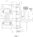
- FIG. 1 is a block diagram of an apparatus 1 for guiding a biomedical electrode according to an embodiment of the present invention.
- FIG. 2 is a block diagram of a positional information processing apparatus 10 .
- FIG. 3 shows a myoelectric potential distribution map 30 which a muscle position detection unit 3 generates from potentials detected by all myoelectric detection electrodes 21 ( m, n ).
- FIG. 4A is an explanatory diagram showing images processed by the positional information processing apparatus 10 , showing a still image p 1 of an electrode sheet 20 attached to a body surface 120 of a muscle 110 .
- FIG. 4B is an explanatory diagram showing images processed by the positional information processing apparatus 10 , showing a muscle position display map image p 2 in which marks 31 a indicating the position of the muscle 110 and a mark 31 b indicating the position of a neuromuscular junction 112 a are superposed and displayed on the body surface 120 on the basis of relative positions of the muscle 110 and the neuromuscular junction 112 a to the body surface 120 , detected by a muscle position detection unit 3 .
- FIG. 4C is an explanatory diagram showing images processed by the positional information processing apparatus 10 , showing a moving image p 3 in which biomedical electrodes 4 to be brought close to the body surface 120 are captured.
- FIG. 4D is an explanatory diagram showing images processed by the positional information processing apparatus 10 , showing a moving image p 4 obtained by combining the still image p 2 with the moving image p 3 so that the outlines of the body surface 120 coincide.
- FIG. 5 is a schematic diagram showing a related evaluation apparatus 100 which detects muscle action potentials from a plurality of respective myoelectric detection electrodes 101 put in close contact with the body surface 120 of the muscle 110 .
- FIG. 6A is an explanatory diagram showing a state in which a pair of adjoining myoelectric detection electrodes 101 a and 101 b are in close contact with positions on both sides of a body surface 120 with a neuromuscular junction 112 a interposed therebetween.
- FIG. 6B is an explanatory diagram showing a state in which the pair of adjoining myoelectric detection electrodes 101 a and 101 b are in close contact with positions on the body surface 120 across a running direction of muscle fibers 110 a.
- the apparatus 1 for guiding a biomedical electrode includes an electrode sheet 20 , 64 comparison circuits 13 , 13 , . . . , a logger 15 , a camera 16 , a positional information processing apparatus 10 , and a display device 17 .
- Sixty-four myoelectric detection electrodes 21 ( m, n ) to be brought into close contact with a living body surface (body surface) 120 of a muscle 110 are attached to the electrode sheet 20 .
- each compare potentials appearing at the respective myoelectric detection electrodes 21 ( m, n ) with a ground potential, and output the results as muscle action potentials to the logger 15 .
- the logger 15 records the muscle action potentials output from the comparison circuits 13 , 13 , . . . with elapsed time.
- the camera 16 captures a still image and a moving image of the living body surface 120 of the muscle 110 .
- the positional information processing apparatus 10 detects relative positions of the muscle 110 and a neuromuscular junction 112 a of the muscle 110 to the living body surface 120 from the results recorded in the logger 15 .
- the positional information processing apparatus 10 On the basis of the relative position information, the positional information processing apparatus 10 generates a composite moving image by adding marks 31 a indicating the position of the muscle 110 and a mark 31 b indicating the position of the neuromuscular junction 112 a to the moving image captured by the camera 16 .
- the display device 17 displays the composite moving image generated by the positional information processing apparatus 10 .
- the electrode sheet 20 includes a flexible printed wiring board made of a flexible insulating sheet of PET or the like.
- a ground electrode 5 set to a ground potential, the 64 myoelectric detection electrodes 21 ( m, n ), and 64 lead traces 6 connected to the respective myoelectric detection electrodes 21 ( m, n ) are formed on the bottom side of the insulating sheet by printing.
- the 64 myoelectric detection electrodes 21 ( m, n ) are arranged in respective positions in a 13-row by 5-column matrix, except the first-row first-column position at the upper left corner of the bottom of the insulating sheet.
- the 64 lead traces 6 are laid from the respective myoelectric detection electrodes 21 ( m, n ) to tail portions at the four corners of the insulating sheet.
- the 64 lead traces 6 are connected to noninverting inputs of the respective 64 comparison circuits 13 , 13 , . . . via connection cables.
- the lead traces 6 are covered with a resist at the side opposed to the body surface and thereby insulated from the body surface.
- the muscle 110 which to detect the relative position of and the relative position of the neuromuscular junction 112 a of with respect to the living body surface 120 is a brachial muscle 110 .
- the electrode sheet 20 is shaped to cover the living body surface 120 under which the brachial muscle 110 is estimated to be.
- the 64 myoelectric detection electrodes 21 ( m, n ) make close contact with respective different positions distributed over the living body surface 120 of the brachial muscle 110 . Potentials appearing at the close contact positions are output to the noninverting inputs of the comparison circuits 13 .
- the comparison circuits 13 output the potentials appearing at the respective myoelectric detection electrodes 21 ( m, n ), compared with the ground potential, to the logger 15 .
- the logger 15 records the potentials detected by all the myoelectric detection electrodes 21 ( m, n ), output from the comparison circuits 13 , 13 , . . . , and outputs the recorded potentials to the positional information processing apparatus 10 each time a certain time elapses.
- the positional information processing apparatus 10 includes a muscle position detection unit 3 , an image recognition unit 7 , an image storage unit 8 , and an image composition unit 9 .
- the potentials detected from all the myoelectric detection electrodes 21 ( m, n ) are input to the muscle position detection unit 3 from the logger 15 each time a certain time elapses.
- a still image p 1 shown in FIG. 4A is input to the image recognition unit 7 from the camera 16 .
- the image storage unit 8 temporarily stores a muscle position display map image p 2 shown in FIG. 4B , which is input from the muscle position detection unit 3 .
- the image composition unit 9 outputs a composite moving image p 4 shown in FIG. 4D to the display device 17 .
- the composite moving image p 4 is obtained by combining the moving image p 3 shown in FIG. 4C , input from the camera 16 , with the muscle position display map image p 2 shown in FIG. 4B , read from the image storage unit 8 .
- the muscle position detection unit 3 of the positional information processing apparatus 10 virtually generates a myoelectric potential distribution map 30 such as shown in FIG. 3 .
- the myoelectric potential distribution map 30 shows a relationship between the close contact positions of all the myoelectric detection electrodes 21 ( m, n ) and the potentials detected by the myoelectric detection electrodes 21 ( m, n ) at the close contact positions.
- muscle action potentials are detected from myoelectric detection electrodes 21 ( m, n ) that are in close contact with the living body surface 120 of the brachial muscle 110 . More specifically, the myoelectric detection electrodes 21 ( m, n ) in close contact with the living body surface 120 of the brachial muscle 110 detect muscle action potentials having levels corresponding to the distances from the brachial muscle 110 to the close contact positions of the myoelectric detection electrodes 21 ( m, n ). No muscle action potential is detected from myoelectric detection electrodes 21 ( m, n ) that are in close contact with positions of the living body surface 120 off the brachial muscle 110 .
- the muscle position detection unit 3 can thus detect the relative position of the brachial muscle 110 to the position where the electrode sheet 20 is adhered to the living body surface 120 on the basis of the myoelectric potential distribution map 30 virtually generated from the potentials detected by all the myoelectric detection electrodes 21 ( m, n ).
- a muscle action potential occurring at a neuromuscular junction 112 a propagates along muscle fibers 110 a of the brachial muscle 110 .
- the muscle action potential is therefore successively detected by myoelectric detection electrodes 21 ( m, n ) that are in close contact with different positions of the living body surface 120 along the muscle fibers 110 a along which the muscle action potential propagates.
- the muscle position detection unit 3 compares the potentials detected by all the myoelectric detection electrodes 21 ( m, n ), input from the logger 15 each time a certain time elapses, and virtually generates the myoelectric potential distribution map 30 .
- the muscle position detection unit 3 can detect a relative position of the neuromuscular junction 112 a to the position where the electrode sheet 20 is adhered to the living body surface 120 , and a running direction of the muscle fibers 110 a of the brachial muscle 110 .
- the camera 16 operates in a still image mode in which to capture a still image, and a moving image mode in which to capture a moving image.
- the camera 16 outputs the still image p 1 , in which the electrode sheet 20 is captured in close contact with the living body surface 120 of the brachial muscle 110 , to the image recognition unit 7 of the positional information processing apparatus 10 .
- the image recognition unit 7 extracts the outline of the living body surface 120 of the brachial muscle 110 and feature portions expressing a relationship of the adhering position of the electrode sheet 20 to the living body surface 120 from the input still image p 1 .
- the image recognition unit 7 outputs the outline and the feature portions to the muscle position detection unit 3 .
- the muscle position detection unit 3 can detect the relative positions of the brachial muscle 110 and the neuromuscular junction 112 a to the electrode sheet 20 adhered to the living body surface 120 and the running direction of the muscle fibers 110 a of the brachial muscle 110 from the myoelectric potential distribution map 30 .
- the muscle position detection unit 3 can thus detect the relative positions of the brachial muscle 110 and the neuromuscular junction 112 a to the living body surface 120 and the running direction of the muscle fibers 110 a of the brachial muscle 110 via the common electrode sheet 20 .
- the muscle position detection unit 3 uses the detected relative position information to generate the muscle position display map image p 2 .
- marks 31 a indicating the outline and the running direction (longitudinal direction) of the brachial muscle 110 and a mark 31 b indicating the position of the neuromuscular junction 112 a are added within the outline of the living body surface 120 of the brachial muscle 110 , input from the image recognition unit 7 .
- the muscle position detection unit 3 outputs the muscle position display map image p 2 to the image storage unit 8 .
- the muscle position display map image p 2 in which the marks 31 a and 31 b are displayed within the outline of the living body surface 120 of the brachial muscle 110 is relative position information indicating the relative positions of the brachial muscle 110 and the neuromuscular junction 112 a to the living body surface 120 .
- the image storage unit 8 stores the muscle position display map image p 2 as brachial muscle relative position information.
- a muscle position display map image p 2 indicating the relative position of the voluntary muscle 110 to the living body surface 120 is obtained in a similar manner.
- the image storage unit 8 can thus store relative position information about various types of voluntary muscles 110 . After relative position information about a desired voluntary muscle 110 is stored into the image storage unit 8 , the electrode sheet 20 and the positional information processing unit 10 may be disconnected.
- the camera 16 is switched to the moving image mode.
- the camera 16 captures a moving image of the biomedical electrodes 4 to be brought close to the living body surface 120 .
- the camera 16 operating in the moving image mode captures the moving image p 3 shown in FIG. 4C , of a state in which the biomedical electrodes 4 are brought close to the living body surface 120 of the brachial muscle 110 .
- the moving image p 3 is output to the image composition unit 9 of the positional information processing apparatus 10 .
- the image composition unit 9 reads the muscle position display map image p 2 of the same brachial muscle 110 .
- the muscle position display map image p 2 is the brachial muscle relative position information stored in the image storage unit 8 .
- the image composition unit 9 extracts common features of the living body surface 120 (for example, the outlines of the living body surface 120 ) in the moving image p 3 and the muscle position display map image p 2 .
- the image composition unit 9 superposes the muscle position display map image p 2 on the moving image p 3 so that the extracted feature portion images coincide, whereby the composite moving image p 4 shown in FIG. 4D is generated.
- the composite moving image p 4 generated by the image composition unit 9 is output to the display device 17 and continuously displayed on a display of the display device 17 .
- the composite moving image p 4 displays the marks 31 a indicating the outline and the longitudinal direction of the brachial muscle 110 , the mark 31 b indicating the position of the neuromuscular junction 112 a in the living body surface 120 , and the biomedical electros 4 brought close to the living body surface 120 .
- the operator can thus guide the biomedical electrodes 4 into close contact with optimum positions on the living body surface 120 of the brachial muscle 110 while checking the current positions of the biomedical electrodes 4 with respect to the brachial muscle 110 and the neuromuscular junction 112 on the composite moving image p 4 .
- the three biomedical electrodes 4 , 4 , 4 serving as a pair of stimulating electrodes and a ground electrode are brought into close contact with the living body surface 120 for the purpose of muscle training of the brachial muscle 110 .
- a stimulating electrode serving as a positive electrode, a stimulating electrode serving as a negative electrode, and the ground electrode are brought into close contact with three positions on the living body surface 120 one by one along the longitudinal direction of the outline of the brachial muscle 110 displayed on the display device 17 .
- the composition, the degree of fatigue, and the like of the muscle 110 are detected from the level of the muscle action potential occurring in the muscle 110 or the propagation velocity MFCV of the muscle action potential.
- a plurality of biomedical electrodes 4 for detecting the muscle action potential are brought into close contact with different positions on the living body surface 120 on one side of the neuromuscular junction 112 a in the longitudinal direction of the brachial muscle 110 , on the basis of the outline of the brachial muscle 110 and the position of the neuromuscular junction 112 a displayed on the display device 17 .
- Various units of the foregoing positional information processing apparatus 10 can be constituted by executing application software installed on a portable information device such as a mobile phone.
- the positional information processing apparatus 10 , the camera 16 , and the display device 17 may be integrally configured as a camera-equipped smartphone.
- the relative position information indicating the relative positions of the voluntary muscle 110 and the neuromuscular junction 112 a to the living body surface 120 is stored as the muscle position display map image p 2 in the image storage unit 8 .
- the relative positions of the voluntary muscle 110 and the neuromuscular 112 a may be expressed, for example, by position coordinates with the origin at a specific position of the living body surface 120 as long as the relative positions can be identified.
- the moving image p 4 generated by combining the muscle position display map image p 2 with the captured moving image p 3 of the biomedical electrodes 4 is displayed on the display device 17 , and the biomedical electrodes 4 are guided to the close contact positions.
- the positions of the voluntary muscle 110 and the neuromuscular junction 112 a may be projected on the living body surface 120 on the basis of the relative position information indicating the relative positions of the voluntary muscle 110 and the neuromuscular junction 112 a .
- Distances between the positions of the voluntary muscle 110 and neuromuscular junction 112 a and the biomedical electrodes 4 may be notified to the user by sound or numerical indications so that the biomedical electrodes 4 are guided into optimum close contact positions.
- the muscle position detection unit 3 detects the relative positions of the voluntary muscle 110 and the neuromuscular junction 112 a to the living body surface 120 and the running direction of the muscle fibers 110 a . However, part of the positions and direction may be detected and stored as the relative position information.
- the myoelectric detection electrodes 21 ( m, n ) for detecting the relative positions of the voluntary muscle 110 and the neuromuscular junction 112 a are arranged in respective positions of the matrix configuration.
- the myoelectric detection electrodes 21 ( m, n ) may be arranged in arbitrary positions as long as a plurality of myoelectric detection electrodes are in close contact with distributed positions of the living body surface 120 and the relative positions of the respective close contact positions to the living body surface 120 can be identified.
- the embodiment of the present invention is suitable for a muscle training system in which biomedical electrodes are brought into close contact with a living body surface of a muscle for the purpose of applying an electrical stimulus to the muscle.
- Dedicated circuitry may include digital and/or analog hardware circuits and may include integrated circuits (IC) and/or discrete circuits.
- Programmable circuitry may include reconfigurable hardware circuits comprising logical AND, OR, XOR, NAND, NOR, and other logical operations, flip-flops, registers, memory elements, etc., such as field-programmable gate arrays (FPGA), programmable logic arrays (PLA), etc.
- Computer-readable media may include any tangible device that can store instructions for execution by a suitable device, such that the computer-readable medium having instructions stored therein comprises an article of manufacture including instructions which can be executed to create means for performing operations specified in the block diagrams.
- Examples of computer-readable media may include an electronic storage medium, a magnetic storage medium, an optical storage medium, an electromagnetic storage medium, a semiconductor storage medium, etc.
- Computer-readable media may include a floppy disk, a diskette, a hard disk, a random access memory (RAM), a read-only memory (ROM), an erasable programmable read-only memory (EPROM or Flash memory), an electrically erasable programmable read-only memory (EEPROM), a static random access memory (SRAM), a compact disc read-only memory (CD-ROM), a digital versatile disk (DVD), a BLU-RAY® disc, a memory stick, an integrated circuit card, etc.
- RAM random access memory
- ROM read-only memory
- EPROM or Flash memory erasable programmable read-only memory
- EEPROM electrically erasable programmable read-only memory
- SRAM static random access memory
- CD-ROM compact disc read-only memory
- DVD digital versatile disk
- BLU-RAY® disc a memory stick, an integrated circuit card, etc.
- Computer-readable instructions may include assembler instructions, instruction-set-architecture (ISA) instructions, machine instructions, machine dependent instructions, microcode, firmware instructions, state-setting data, or either source code or object code written in any combination of one or more programming languages, including an object oriented programming language such as Smalltalk, JAVA, C++, etc., and conventional procedural programming languages, such as the “C” programming language or similar programming languages.
- ISA instruction-set-architecture
- machine instructions machine dependent instructions
- microcode firmware instructions
- state-setting data or either source code or object code written in any combination of one or more programming languages, including an object oriented programming language such as Smalltalk, JAVA, C++, etc., and conventional procedural programming languages, such as the “C” programming language or similar programming languages.
- Computer-readable instructions may be provided to a processor of a general purpose computer, special purpose computer, or other programmable data processing apparatus, or to programmable circuitry, locally or via a local area network (LAN), wide area network (WAN) such as the Internet, etc., to execute the computer-readable instructions to create means for performing operations specified in the block diagrams.
- processors include computer processors, processing units, microprocessors, digital signal processors, controllers, microcontrollers, etc.
- muscle position detection unit (muscle position detecting unit)
Landscapes
- Health & Medical Sciences (AREA)
- Life Sciences & Earth Sciences (AREA)
- Molecular Biology (AREA)
- Surgery (AREA)
- Biophysics (AREA)
- Pathology (AREA)
- Engineering & Computer Science (AREA)
- Biomedical Technology (AREA)
- Heart & Thoracic Surgery (AREA)
- Medical Informatics (AREA)
- Veterinary Medicine (AREA)
- Physics & Mathematics (AREA)
- Animal Behavior & Ethology (AREA)
- General Health & Medical Sciences (AREA)
- Public Health (AREA)
- Nuclear Medicine, Radiotherapy & Molecular Imaging (AREA)
- Neurology (AREA)
- Radiology & Medical Imaging (AREA)
- Physical Education & Sports Medicine (AREA)
- Measurement And Recording Of Electrical Phenomena And Electrical Characteristics Of The Living Body (AREA)
- Electrotherapy Devices (AREA)
Abstract
Description
Claims (5)
Applications Claiming Priority (2)
| Application Number | Priority Date | Filing Date | Title |
|---|---|---|---|
| JP2017-39545 | 2017-03-02 | ||
| JP2017039545A JP2018143353A (en) | 2017-03-02 | 2017-03-02 | Biological electrode induction device |
Publications (2)
| Publication Number | Publication Date |
|---|---|
| US20180249923A1 US20180249923A1 (en) | 2018-09-06 |
| US10602952B2 true US10602952B2 (en) | 2020-03-31 |
Family
ID=63357044
Family Applications (1)
| Application Number | Title | Priority Date | Filing Date |
|---|---|---|---|
| US15/702,711 Expired - Fee Related US10602952B2 (en) | 2017-03-02 | 2017-09-12 | Apparatus for guiding biomedical electrode |
Country Status (3)
| Country | Link |
|---|---|
| US (1) | US10602952B2 (en) |
| JP (1) | JP2018143353A (en) |
| CN (1) | CN108523887A (en) |
Families Citing this family (4)
| Publication number | Priority date | Publication date | Assignee | Title |
|---|---|---|---|---|
| CN110074760B (en) * | 2019-04-28 | 2021-11-23 | 太平洋未来科技(深圳)有限公司 | Instrument capable of reading sensor value for measuring human muscle movement strength |
| KR20220073068A (en) * | 2020-11-26 | 2022-06-03 | (주) 로임시스템 | Biological signal measuring system combinded with smart clothes |
| CN113520412A (en) * | 2021-07-15 | 2021-10-22 | 浙江远翔医疗科技有限公司 | A kind of electromyography intelligent detection device and operation method |
| CN117503062B (en) * | 2023-11-21 | 2024-04-09 | 欣颜时代(广州)技术有限公司 | Neural detection control method, device, equipment and storage medium of beauty instrument |
Citations (6)
| Publication number | Priority date | Publication date | Assignee | Title |
|---|---|---|---|---|
| US20050288586A1 (en) * | 2004-06-28 | 2005-12-29 | Bozidar Ferek-Petric | Electrode location mapping system and method |
| US20060129057A1 (en) * | 2002-09-11 | 2006-06-15 | Satoshi Maekawa | Active muscle display device |
| US20070074728A1 (en) * | 2005-05-13 | 2007-04-05 | Rea James L | Endotracheal electrode and optical positioning device |
| US20080077041A1 (en) * | 2006-08-23 | 2008-03-27 | Gozani Shai N | Novel method and apparatus for determining optimal neuromuscular detection sites, novel diagnostic biosensor array formed in accordance with the same, and novel method for testing a patient using the novel diagnostic biosensor array |
| US20170188880A1 (en) * | 2015-08-21 | 2017-07-06 | Gal Sela | Method, system and apparatus for tracking cortical stimulator locations |
| US20170197074A1 (en) | 2014-06-04 | 2017-07-13 | Nihon Kohden Corporation | Rehabilitation assistance system |
Family Cites Families (6)
| Publication number | Priority date | Publication date | Assignee | Title |
|---|---|---|---|---|
| JPS59200632A (en) * | 1983-04-26 | 1984-11-14 | 工業技術院長 | Apparatus for detecting nerve muscle junction distribution by muscle potential multi-point measurement |
| JPS61228827A (en) * | 1985-04-03 | 1986-10-13 | 工業技術院長 | Apparatus for detecting nerve domination band in muscle |
| JP4340936B2 (en) * | 1999-07-15 | 2009-10-07 | ソニー株式会社 | Electrical stimulation device and force / tactile sense presentation device using electrical stimulation |
| JP2002287869A (en) * | 2001-03-26 | 2002-10-04 | System Lsi Kk | EMG signal discrimination method and input device using EMG signal |
| EP2318093B1 (en) * | 2008-07-02 | 2019-11-13 | Sage Products, LLC | Systems for automated muscle stimulation |
| KR20140086179A (en) * | 2012-12-28 | 2014-07-08 | 삼성전자주식회사 | System and method of skeletal muscle stimulation |
-
2017
- 2017-03-02 JP JP2017039545A patent/JP2018143353A/en active Pending
- 2017-09-12 US US15/702,711 patent/US10602952B2/en not_active Expired - Fee Related
-
2018
- 2018-02-24 CN CN201810157257.6A patent/CN108523887A/en active Pending
Patent Citations (6)
| Publication number | Priority date | Publication date | Assignee | Title |
|---|---|---|---|---|
| US20060129057A1 (en) * | 2002-09-11 | 2006-06-15 | Satoshi Maekawa | Active muscle display device |
| US20050288586A1 (en) * | 2004-06-28 | 2005-12-29 | Bozidar Ferek-Petric | Electrode location mapping system and method |
| US20070074728A1 (en) * | 2005-05-13 | 2007-04-05 | Rea James L | Endotracheal electrode and optical positioning device |
| US20080077041A1 (en) * | 2006-08-23 | 2008-03-27 | Gozani Shai N | Novel method and apparatus for determining optimal neuromuscular detection sites, novel diagnostic biosensor array formed in accordance with the same, and novel method for testing a patient using the novel diagnostic biosensor array |
| US20170197074A1 (en) | 2014-06-04 | 2017-07-13 | Nihon Kohden Corporation | Rehabilitation assistance system |
| US20170188880A1 (en) * | 2015-08-21 | 2017-07-06 | Gal Sela | Method, system and apparatus for tracking cortical stimulator locations |
Non-Patent Citations (1)
| Title |
|---|
| Ken Nishihara et al., Estimation of muscle fiber conduction velocity by pulse detection averaging method and analysis of muscle fatigue,Senmon rehabil,2003, pp. 42-47, vol. 2,Senmon Rehabilitation Research Society, Japan. |
Also Published As
| Publication number | Publication date |
|---|---|
| JP2018143353A (en) | 2018-09-20 |
| CN108523887A (en) | 2018-09-14 |
| US20180249923A1 (en) | 2018-09-06 |
Similar Documents
| Publication | Publication Date | Title |
|---|---|---|
| US10602952B2 (en) | Apparatus for guiding biomedical electrode | |
| Lin et al. | Automatic real-time occupational posture evaluation and select corresponding ergonomic assessments | |
| Wang et al. | Automatic evaluation of the degree of facial nerve paralysis | |
| Sapkaroski et al. | Quantification of student radiographic patient positioning using an immersive virtual reality simulation | |
| Hoffmann et al. | Bedside ultrasound of the neck confirms endotracheal tube position in emergency intubations | |
| Wijayasinghe et al. | Human–robot gesture analysis for objective assessment of autism spectrum disorder | |
| US20150279220A1 (en) | Method and system for analyzing exam-taking behavior and improving exam-taking skills | |
| CN106295110B (en) | Medical image processing method and image processing system | |
| Creedle et al. | The impact of education on caregiver burden on two inpatient oncology units | |
| Bischoff et al. | Motor familiarity: Brain activation when watching kinematic displays of one's own movements | |
| Xiao et al. | Extraction and application of deformation-based feature in medical images | |
| Lee et al. | Prototype tactile feedback system for examination by skin touch | |
| US12148239B2 (en) | Information processing apparatus, information processing method, and storage medium | |
| Sang et al. | A novel deep learning method to segment parathyroid glands on intraoperative videos of thyroid surgery | |
| Huda et al. | Developing a real-time hand-gesture recognition technique for wheelchair control | |
| CN115350081B (en) | CPR intelligent training management method and system using computer vision | |
| Kluge et al. | Validating a smartphone-based pedestrian navigation system prototype: an informal eye-tracking pilot test | |
| KR102550724B1 (en) | Augmented reality based cognitive rehabilitation training system and method | |
| Zhang et al. | Real-time chest compression depth, rate, posture, and person detections using binocular vision for cpr training | |
| Kuchtaruk et al. | Assessment of finger dexterity through the DIGITS joint tracking web application—An evaluation study with comparison to the nine-hole pegboard test | |
| Gurari et al. | Ability of individuals with chronic hemiparetic stroke to locate their forearms during single-arm and between-arms tasks | |
| CN119068551A (en) | A method for evaluating radio gymnastics movements based on skeleton structure representation learning | |
| Wen et al. | Using gait videos to automatically assess anxiety | |
| US20240355479A1 (en) | Measurement system, measurement apparatus, measurement data processing method, and measurement data processing program | |
| Shrivastava et al. | Autism spectrum disorder classification of facial images using xception model and transfer learning with image augmentation |
Legal Events
| Date | Code | Title | Description |
|---|---|---|---|
| FEPP | Fee payment procedure |
Free format text: ENTITY STATUS SET TO UNDISCOUNTED (ORIGINAL EVENT CODE: BIG.); ENTITY STATUS OF PATENT OWNER: LARGE ENTITY |
|
| AS | Assignment |
Owner name: SMK CORPORATION, JAPAN Free format text: ASSIGNMENT OF ASSIGNORS INTEREST;ASSIGNORS:EJIRI, KOICHIRO;KONDO, HARUHIKO;SIGNING DATES FROM 20170720 TO 20170725;REEL/FRAME:043566/0688 |
|
| STPP | Information on status: patent application and granting procedure in general |
Free format text: DOCKETED NEW CASE - READY FOR EXAMINATION |
|
| STPP | Information on status: patent application and granting procedure in general |
Free format text: PRE-INTERVIEW COMMUNICATION MAILED |
|
| STPP | Information on status: patent application and granting procedure in general |
Free format text: NON FINAL ACTION MAILED |
|
| STPP | Information on status: patent application and granting procedure in general |
Free format text: RESPONSE TO NON-FINAL OFFICE ACTION ENTERED AND FORWARDED TO EXAMINER |
|
| ZAAA | Notice of allowance and fees due |
Free format text: ORIGINAL CODE: NOA |
|
| ZAAB | Notice of allowance mailed |
Free format text: ORIGINAL CODE: MN/=. |
|
| STPP | Information on status: patent application and granting procedure in general |
Free format text: PUBLICATIONS -- ISSUE FEE PAYMENT RECEIVED |
|
| STPP | Information on status: patent application and granting procedure in general |
Free format text: PUBLICATIONS -- ISSUE FEE PAYMENT VERIFIED |
|
| STCF | Information on status: patent grant |
Free format text: PATENTED CASE |
|
| FEPP | Fee payment procedure |
Free format text: MAINTENANCE FEE REMINDER MAILED (ORIGINAL EVENT CODE: REM.); ENTITY STATUS OF PATENT OWNER: LARGE ENTITY |
|
| LAPS | Lapse for failure to pay maintenance fees |
Free format text: PATENT EXPIRED FOR FAILURE TO PAY MAINTENANCE FEES (ORIGINAL EVENT CODE: EXP.); ENTITY STATUS OF PATENT OWNER: LARGE ENTITY |
|
| STCH | Information on status: patent discontinuation |
Free format text: PATENT EXPIRED DUE TO NONPAYMENT OF MAINTENANCE FEES UNDER 37 CFR 1.362 |
|
| FP | Lapsed due to failure to pay maintenance fee |
Effective date: 20240331 |