US10602446B2 - Method and receiving device for estimating reception time of beacon signal - Google Patents
Method and receiving device for estimating reception time of beacon signal Download PDFInfo
- Publication number
- US10602446B2 US10602446B2 US16/377,790 US201916377790A US10602446B2 US 10602446 B2 US10602446 B2 US 10602446B2 US 201916377790 A US201916377790 A US 201916377790A US 10602446 B2 US10602446 B2 US 10602446B2
- Authority
- US
- United States
- Prior art keywords
- beacon signal
- reception time
- tsf
- beacon
- rtc
- Prior art date
- Legal status (The legal status is an assumption and is not a legal conclusion. Google has not performed a legal analysis and makes no representation as to the accuracy of the status listed.)
- Active
Links
Images


Classifications
-
- H—ELECTRICITY
- H04—ELECTRIC COMMUNICATION TECHNIQUE
- H04W—WIRELESS COMMUNICATION NETWORKS
- H04W56/00—Synchronisation arrangements
- H04W56/004—Synchronisation arrangements compensating for timing error of reception due to propagation delay
- H04W56/005—Synchronisation arrangements compensating for timing error of reception due to propagation delay compensating for timing error by adjustment in the receiver
-
- H—ELECTRICITY
- H04—ELECTRIC COMMUNICATION TECHNIQUE
- H04W—WIRELESS COMMUNICATION NETWORKS
- H04W52/00—Power management, e.g. Transmission Power Control [TPC] or power classes
- H04W52/02—Power saving arrangements
- H04W52/0209—Power saving arrangements in terminal devices
- H04W52/0212—Power saving arrangements in terminal devices managed by the network, e.g. network or access point is leader and terminal is follower
- H04W52/0216—Power saving arrangements in terminal devices managed by the network, e.g. network or access point is leader and terminal is follower using a pre-established activity schedule, e.g. traffic indication frame
-
- H—ELECTRICITY
- H04—ELECTRIC COMMUNICATION TECHNIQUE
- H04W—WIRELESS COMMUNICATION NETWORKS
- H04W48/00—Access restriction; Network selection; Access point selection
- H04W48/16—Discovering, processing access restriction or access information
-
- H—ELECTRICITY
- H04—ELECTRIC COMMUNICATION TECHNIQUE
- H04W—WIRELESS COMMUNICATION NETWORKS
- H04W52/00—Power management, e.g. Transmission Power Control [TPC] or power classes
- H04W52/02—Power saving arrangements
- H04W52/0209—Power saving arrangements in terminal devices
-
- H—ELECTRICITY
- H04—ELECTRIC COMMUNICATION TECHNIQUE
- H04W—WIRELESS COMMUNICATION NETWORKS
- H04W52/00—Power management, e.g. Transmission Power Control [TPC] or power classes
- H04W52/02—Power saving arrangements
- H04W52/0209—Power saving arrangements in terminal devices
- H04W52/0225—Power saving arrangements in terminal devices using monitoring of external events, e.g. the presence of a signal
- H04W52/0248—Power saving arrangements in terminal devices using monitoring of external events, e.g. the presence of a signal dependent on the time of the day, e.g. according to expected transmission activity
-
- H—ELECTRICITY
- H04—ELECTRIC COMMUNICATION TECHNIQUE
- H04W—WIRELESS COMMUNICATION NETWORKS
- H04W56/00—Synchronisation arrangements
- H04W56/0055—Synchronisation arrangements determining timing error of reception due to propagation delay
- H04W56/0065—Synchronisation arrangements determining timing error of reception due to propagation delay using measurement of signal travel time
-
- H—ELECTRICITY
- H04—ELECTRIC COMMUNICATION TECHNIQUE
- H04W—WIRELESS COMMUNICATION NETWORKS
- H04W56/00—Synchronisation arrangements
- H04W56/0055—Synchronisation arrangements determining timing error of reception due to propagation delay
- H04W56/0095—Synchronisation arrangements determining timing error of reception due to propagation delay estimated based on signal strength
-
- H—ELECTRICITY
- H04—ELECTRIC COMMUNICATION TECHNIQUE
- H04W—WIRELESS COMMUNICATION NETWORKS
- H04W84/00—Network topologies
- H04W84/02—Hierarchically pre-organised networks, e.g. paging networks, cellular networks, WLAN [Wireless Local Area Network] or WLL [Wireless Local Loop]
- H04W84/10—Small scale networks; Flat hierarchical networks
- H04W84/12—WLAN [Wireless Local Area Networks]
-
- Y—GENERAL TAGGING OF NEW TECHNOLOGICAL DEVELOPMENTS; GENERAL TAGGING OF CROSS-SECTIONAL TECHNOLOGIES SPANNING OVER SEVERAL SECTIONS OF THE IPC; TECHNICAL SUBJECTS COVERED BY FORMER USPC CROSS-REFERENCE ART COLLECTIONS [XRACs] AND DIGESTS
- Y02—TECHNOLOGIES OR APPLICATIONS FOR MITIGATION OR ADAPTATION AGAINST CLIMATE CHANGE
- Y02D—CLIMATE CHANGE MITIGATION TECHNOLOGIES IN INFORMATION AND COMMUNICATION TECHNOLOGIES [ICT], I.E. INFORMATION AND COMMUNICATION TECHNOLOGIES AIMING AT THE REDUCTION OF THEIR OWN ENERGY USE
- Y02D30/00—Reducing energy consumption in communication networks
- Y02D30/70—Reducing energy consumption in communication networks in wireless communication networks
Definitions
- the present disclosure relates to a method for estimating reception time of beacon signal and a receiving device for estimating reception time of beacon signal.
- Wireless local area network which is one of developing wireless communication technology, is a technology for laptops, mobile devices, or other terminal stations (hereinafter, STAs) to link to the interact from home, company or WLAN server using wireless radio technology.
- STAs terminal stations
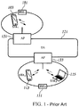
- FIG. 1 illustrates a structure of 802.11 wireless local area network (WLAN) system which is created by Institute of Electrical and Electronics Engineers (IEEE).
- WLAN wireless local area network
- IEEE 802.11 WLAN system includes a plurality of components which works mutually to provide STAs portable wireless local network.
- BSS Basic service set
- FIG. 1 takes WLAN consists of BSS 101 and BSS 111 and one distribution system (DS) 121 as an example.
- a first BSS 101 includes one member STA 103 .
- a second BSS 111 includes two members, STA 113 and STA 115 .
- DS 121 is connected to both first BSS 101 and second BSS 111 .
- Access point (hereinafter AP) 131 , 133 can receive STAs and can be view as a STA. That is, AP 131 , 133 can transmit data between BSS and DS.
- AP Access point
- STAs can be terminals, wireless transceivers, user devices, mobile stations, portable terminals, user terminals, receiving devices, etc.
- AP can be a base station (BS), a node B, an evolved node B (eNodeB) in a WLAN system or any kind of access points connected between WLAN and the internet.
- BS base station
- eNodeB evolved node B
- APs periodically or non-periodically transmit beacon signals so that STAs can implement synchronization with STAs according to the received beacon signals.
- STAs need to scan channels before receiving and transmitting data in WLAN system.
- STAs keep consuming power when scanning channels.
- the power consumption in receiving mode is higher than transmitting mode.
- High power consumption in receiving mode makes usage time of STA become shorter because STAs usually utilize batteries as power source.
- PM power management
- PM modes can be divided into active mode and power save (PS) mode.
- STAs usually utilize active mode to remain in wake-up mode. Transmission and reception of signal frames or channel scanning can be implemented normally in wake-up mode. STAs switch between sleep mode and wakeup mode to save power consumption. STAs do not transmit nor receive signal frame and do not scan channel either.
- STAs cannot receive and transmit signal frames in sleep mode, thus, it is impossible for STAs to always remain in sleep mode. If reception or transmission of signal frames is required, STAs have to switch to wake-up mode from sleep mode. However, if APs require to receive or transmit signal frames to STAs, STAs will be unable to transmit signal frames required by Aps in sleep mode and unable to know the requirement of receiving signal frames transmitted from Aps. In order to know whether the reception of signal frame transmitted from APs is required or not, STAB need to switch to wake-up mode from sleep mode in specific period. The specific period can be the period of beacon signals transmitted by APs. Thus, STAs need to estimate reception time of beacon signals precisely.
- the object of the present disclosure is providing a receiving device which can precisely estimate the reception time of beacon signals in low power consumption.
- the other object of the present disclosure is enhancing the successful reception proportion for receiving device to receive beacon signals from AP.
- the other object of the present disclosure is reducing power consumption by precisely estimating the reception time of beacon signals.
- the other object of the present disclosure is reducing affection cause by the time shift of the inner clock within AP.
- the method for estimating reception time of beacon signals of the present disclosure includes: receiving a first beacon signal from a transmitting device, checking the real-time clock of a receiving device, checking the timing synchronization function (TSF) of the first beacon signal, and estimating the reception time of a next beacon signal according to the real-time clock, the TSF of the first beacon signal and a period of the first beacon signal.
- TSF timing synchronization function
- the present disclosure further provides a receiving device for estimating reception time of beacon signals which includes a receiving block, a clock, and a control block.
- the receiving block receives a first beacon signal from a transmitting block.
- the control block checks a real-time clock of the receiving device, checks a timing synchronization function (TSF) of the first beacon signal, and estimates a reception time of a next beacon according to the real-time clock of the receiving device and the TSF of the first beacon signal.
- TSF timing synchronization function
- the embodiments of the present disclosure can reduce the failure of beacon signal reception.
- receiving device can precisely estimate the reception time of beacon signal so that await period, i.e. period for receiving device in wake-up mode, becomes shorter.
- the receiving device can reduce the failure of beacon signal reception and reduce the power consumption when keep the network accessible.
- the receiving device can tolerate larger time shift of real-time clock and the reception of beacon signals can be improved.
- the receiving device can extend the period of power-saving mode and reduce the affection, which may result in failure of beacon signals reception, caused from the time shift of inner real-time clock of the receiving device.
- FIG. 1 illustrates a structure of 802.11 wireless local area network system created by Institute of Electrical and Electronics Engineers (IEEE 802.11 WLAN system).
- IEEE 802.11 WLAN system Institute of Electrical and Electronics Engineers
- FIG. 2 illustrates reception time of beacon signals of a receiving device STA when transmission delay occurs on an AP.
- FIG. 3 illustrates reception time of beacon signals estimated by the receiving device STA when the receiving device STA has negative real-time clock (RTC) time shift.
- RTC real-time clock
- FIG. 4 illustrates reception time of beacon signals estimated by the receiving device STA when the receiving device STA has positive RTC time shit.
- FIG. 5 illustrates reception time of beacon signals estimated by the receiving device STA when AP has transmission shift and receiving device STA has RTC time shift.
- FIG. 6 illustrates reception time of beacon signals estimated by the receiving device STA of the present disclosure.
- FIG. 7 illustrates a structure of the receiving device STA of the present disclosure.
- FIG. 8 illustrates a flow chart for the receiving device STA of the present disclosure to estimate reception time of beacon signals.
- first, second, A, B, (a), (b) are utilized to distinguish different components instead of limiting the arrangements or orders of the embodiments.
- components are “comprised” or “included”, it means the composition may include components which are not mentioned, that is, the composition is not exclusively composed by the mentioned components.
- Terms “unit”, “module”, etc. refer to a component which has at least one function or can deal with at least one process.
- the component can be hardware, software of the combination of hardware and software.
- the present disclosure utilizes IEEE 802.11 system as an example of wireless local area network (WLAN) system.
- WLAN wireless local area network
- any WLAN system which can apply the method for estimating reception time of beacon signal or receiving devices for estimating reception time of beacon signal falls into the scope of the present disclosure.
- FIG. 2 illustrates reception time of beacon signals of a station (STA) when delay happens on access point (AP).
- AP 203 originally schedule to transmit beacon signals at predetermined time t 1 , t 2 , and t 3 .
- Time intervals between the predetermined times can be the period of beacon signal, i.e. interval of transmitting beacon signals (BCN Interval).
- BCN Interval interval of transmitting beacon signals
- AP 203 may not transmit beacon signals due to various reasons.
- AP 203 transmits beacon signals after delay time 211 following by predetermined time t 2 .
- transmitted beacon signals includes timing synchronization function (TSF) which can be utilized by STA 201 to synchronize with AP 203 .
- STA 201 utilized information of beacon signals to update network.
- TSF timing synchronization function
- STA 203 switches to wake-up mode rom sleep mode periodically in order to receive beacon signals transmitted by AP 203 .
- STA 201 analyze the received beacon signals in wake-up mode, if reception or transmission of data is required, STA 201 remains in wake-up mode, if not, STA 201 switches into sleep mode after estimating time for next wake-up.
- STA 201 requires reboot time 213 to switch into wake-up mode during the process of receiving beacon signals.
- STA 201 estimate reception time of next beacon signal, which is so-called target beacon transmission time (TBTT), according to the TSF and the period of beacon signals Which STA 201 received earlier.
- the TSF of the beacon signals may include delayed time when transmission of beacon signals from AP 203 is delayed.
- the reception time of the next beacon signal estimated by STA 201 may be incorrect because the reception time of the next beacon signal (i.e. TBTT) is estimated according to the TSF of previous beacon signals.
- the delay of the TSF of previously received beacon signals result in incorrect estimated reception time of next beacon signal, thus STA 201 cannot successfully receive the next beacon signals.
- STA 201 utilize formula (1) to obtain remainder (R) by dividing TSF of the previously received beacon signals by the period of the beacon signal.
- the period of the beacon refer to the time interval of beacon signals.
- Next TBBT_ B [(TSF of previously received beacon signals)+(period of beacon signals)] ⁇ ( R ) Formula (1)
- NEXT TBTT_B represents the reception time of the next beacon signal.
- FIG. 3 illustrates reception time for receiving device STA to receive beacon signals which have negative real-time clock (RTC) time shift.
- RTC real-time clock
- FIG. 3 takes the RTC time shift of receiving device STA is ⁇ 250 microseconds ( ⁇ s) as an example to clarify the present disclosure.
- AP 203 transmit beacon signals at predetermined time t 1 , t 2 and t 3 .
- STA 201 switch into wake-up mode after time shift 301 following by predetermined time t 2 due to the inner RTC time shift of STA 201 .
- STA 201 estimates the reception time of next beacon signal according to inner RTC of STA 201 thus the estimated reception time of the next beacon will be affected.
- STA 201 switches into wake-up mode after accumulated time shift 305 following by the predetermined t 3 .
- the reception time of the next beacon signal (TBTT) will be mistakenly estimated as time 303 , thus STA 201 miss the time when AP 203 transmits beacon signal and cannot receiving the beacon signals successfully.
- the period (interval) of beacon signals is 3 seconds, the total delay is ⁇ 750 ⁇ s.
- FIG. 4 illustrates reception time of beacon signals when the RTC of the receiving device STA has positive time shift.
- FIG. 4 takes the time shift of the receiving device STA is +250 ⁇ s as an example.
- the only difference between FIG. 3 and FIG. 4 is the time difference change from negative to positive, thus the time for waking STA 201 up becomes earlier instead of later.
- STA 201 will mistakenly estimate reception time of the next beacon signal (TBTT) is time 403 .
- TBTT next beacon signal
- the time shift 401 is 750 ⁇ s.
- the time shift 405 will accumulate longer due to the time shift of time shift of RTC accordingly to FIG. 3 . If STA 201 keeps in power-saving mode for a long time, receiving device STA will be unable to receive beacon signals successfully due to the time shift of RTC.
- AP 203 has inner clock as STA 201 , therefore, transmission shift will occur on AP 203 during transmission due to the time shift of RTC.
- transmission shift refers to shift caused from the time shift of inner clock of transmitting device AP 203 during transmission.
- AP 203 transmit beacon signals at time 501 and 503 accompanied with transmission shift caused from inner clock time shift.
- the transmission delay of beacon signals caused from inner clock time shift accumulates with following of time.
- STA 201 also has RTC time shift 511 and 513 cause from inner clock when STA 201 switches to wake-up mode from sleep mode.
- STA 201 and AP 203 execute in different time domain due to the inner clock time shift, thus, STA 201 and AP 203 cannot synchronize. As a result, it is impossible for STA 201 to receive beacon signals successfully at the estimated reception time of next beacon signal (TBTT) 521 .
- TBTT next beacon signal
- FIG. 6 illustrates the reception time of beacon signals of receiving device STA.
- AP 203 transmits beacon signals with transmission shift caused from inner clock time shift as FIG. 5 . Delay will occur on STA 201 when switch to wake-up mode from sleep mode due to the time shift of inner clock RTC 205 .
- STA 201 estimates the reception time of next beacon signal (TBTT) 621 according to the inner clock RTC (RTC 0 and RTC 1 ) 601 and 603 , and according to the TSFs of the two continuous beacon signals 611 and 613 received previously.
- Inner clock RTC 601 and 603 can be the reception time of beacon signals 611 and 613 respectively.
- STA 201 utilizes formula (2) to calculate slope a according to the inner clock RTC 601 and 603 and the TSFs of the beacon signals 611 and 613 received previously. Then, STA 201 utilize the slope a and formula (3) to estimate the reception time of the next beacon signal (TBTT) 621 .
- RTC N-1 and RTC N-2 represent the reception time of beacon signals 611 and 613 .
- TSF N-1 and TSF N-2 represents the TSF of signals 611 and 613 .
- BCN interval represents period or interval of beacon signals.
- RTC 0 50 ⁇ s and RTC 1 is 100 ⁇ s
- TSF of beacon signal 611 is 200 ⁇ s
- TSF of beacon signal 613 is 300 ⁇ s as an example.
- the reception time of the next beacon signal is 150 ⁇ s.
- FIG. 7 illustrates the structure of receiving device STA 70 .
- Receiving device STA 70 of the present disclosure includes receiving block 701 , real-time clock (RTC) 703 and control block 705 .
- the receiving block 701 and the RTC 703 do not have to isolate from control block 705 and can be intergraded into control block 705 in some embodiments.
- the receiving block 701 receives beacon signals from Aps.
- RTC 703 is an inner clock of the receiving device 70 .
- the control block 705 of the present disclosure is utilized to estimate the reception time of a next beacon signal (TBTT) according to the received beacon signals so that STA can wake-up from sleep mode when reception of beacon signals transmitted by APs is required.
- TBTT next beacon signal
- FIG. 8 illustrates the flow chart of the receiving device STA of the present disclosure.
- STA switches to wake-up mode into sleep mode( 801 ).
- STA receives beacon signals from AP( 803 ). STA checks the RTC of inner clock. STA checks the TSF of received beacon signals. STA estimates the reception time of the next beacon signal (TBTT) ( 809 ). STA switches to wake-up mode from sleep mode ( 811 ).
Landscapes
- Engineering & Computer Science (AREA)
- Computer Networks & Wireless Communication (AREA)
- Signal Processing (AREA)
- Computer Security & Cryptography (AREA)
- Mobile Radio Communication Systems (AREA)
Abstract
Description
Next TBBT_B=[(TSF of previously received beacon signals)+(period of beacon signals)]−(R) Formula (1)
a=(RTCN-1−RTCN-2)/(TSFN-1−TSFN-2) Formula (2)
NEXT TBTT (RTCN)=(RTCN-1 or TSFN-1)+a*BCN interval Formula (3)
Claims (10)
a=RTCN-1−RTCN-2)/(TSFN-1−TSFN-2);
the reception time of the next beacon signal=(RTCN-1 or TSFN-1)+a*(the period of the first beacon signal),
a=(RTCN-1−RTCN-2)/(TSFN-1−TSFN-2);
the reception time of the next beacon signal=(RTCN-1 or TSFN-1)+a*(the period of the first beacon signal),
Applications Claiming Priority (2)
| Application Number | Priority Date | Filing Date | Title |
|---|---|---|---|
| KR10-2018-0042804 | 2018-04-12 | ||
| KR1020180042804A KR20190119400A (en) | 2018-04-12 | 2018-04-12 | A method for efficiently estimating a reception time of a beacon signal and a receiving device there for |
Publications (2)
| Publication Number | Publication Date |
|---|---|
| US20190320387A1 US20190320387A1 (en) | 2019-10-17 |
| US10602446B2 true US10602446B2 (en) | 2020-03-24 |
Family
ID=68162384
Family Applications (1)
| Application Number | Title | Priority Date | Filing Date |
|---|---|---|---|
| US16/377,790 Active US10602446B2 (en) | 2018-04-12 | 2019-04-08 | Method and receiving device for estimating reception time of beacon signal |
Country Status (4)
| Country | Link |
|---|---|
| US (1) | US10602446B2 (en) |
| KR (1) | KR20190119400A (en) |
| CN (1) | CN110381570A (en) |
| TW (1) | TWI677254B (en) |
Citations (42)
| Publication number | Priority date | Publication date | Assignee | Title |
|---|---|---|---|---|
| US20050169233A1 (en) * | 2004-06-30 | 2005-08-04 | Sharp Laboratories Of America, Inc. | System clock synchronization in an ad hoc and infrastructure wireless networks |
| US20050243782A1 (en) * | 2004-03-01 | 2005-11-03 | Sony Corporation | Wireless communication system, wireless communication apparatus, wireless communication method and computer program |
| US20080002632A1 (en) * | 2006-06-29 | 2008-01-03 | Motorola, Inc. | System and method for communicating beacon transmissions in wireless local area network (wlan) systems |
| US20080002633A1 (en) * | 2006-06-29 | 2008-01-03 | Motorola, Inc. | System and method for communicating beacon transmissions in wireless local area network (wlan) systems |
| US20080225768A1 (en) * | 2007-03-13 | 2008-09-18 | Conexant Systems, Inc. | Systems and Methods for Indicating Buffered Data at an Access Point Using a Traffic Indication Map Broadcast |
| US20090097464A1 (en) * | 2003-02-03 | 2009-04-16 | Sony Corporation | Wireless communication system, wireless communication apparatus and wireless communication method and computer program |
| US20100150095A1 (en) * | 2008-12-08 | 2010-06-17 | Xg Technology, Inc. | Network entry procedure in multi-channel mobile networks |
| US7856656B1 (en) * | 2004-09-08 | 2010-12-21 | Airtight Networks, Inc. | Method and system for detecting masquerading wireless devices in local area computer networks |
| US8005515B1 (en) * | 2007-04-04 | 2011-08-23 | Marvell World Trade Ltd. | Beacon miss prevention in power save modes using timing synchronization function |
| US20110216658A1 (en) * | 2010-03-02 | 2011-09-08 | Raul Hernan Etkin | Synchronization in a wireless node |
| US20110216660A1 (en) * | 2010-03-02 | 2011-09-08 | Jung Gun Lee | Synchronization in a wireless node |
| US20110222421A1 (en) * | 2008-09-12 | 2011-09-15 | Suman Jana | Method and System for Detecting Unauthorized Wireless Access Points Using Clock Skews |
| US20110231559A1 (en) * | 2010-03-17 | 2011-09-22 | Nintendo Co., Ltd. | Communication apparatus, computer-readable storage medium having stored therein communication control program, communication control method, and communication system |
| US20130044658A1 (en) * | 2011-08-16 | 2013-02-21 | Utc Fire & Security Corporation | Beacon synchronization in wifi based systems |
| US20130077546A1 (en) * | 2011-09-23 | 2013-03-28 | Qualcomm Atheros, Inc. | Wireless Beacon Reception |
| US8488506B2 (en) * | 2011-06-28 | 2013-07-16 | Qualcomm Incorporated | Oscillator settling time allowance |
| US20130204962A1 (en) * | 2012-02-02 | 2013-08-08 | Texas Instruments Incorporated | Network and peripheral interface circuits, systems and processes |
| US20130272455A1 (en) * | 2012-04-13 | 2013-10-17 | Qualcomm Incorporated | Systems and methods for clock compensation |
| US20140024975A1 (en) * | 2012-07-17 | 2014-01-23 | Liposonix, Inc. | Hifu components with integrated calibration parameters |
| US20140065964A1 (en) * | 2012-09-06 | 2014-03-06 | Nokia Corporation | Method, apparatus, and computer program product for the exchanging of information between wireless devices for joining |
| US20140148099A1 (en) * | 2012-11-26 | 2014-05-29 | Nokia Corporation | Method, apparatus, and computer program product for optimized discovery between mobile devices |
| US20140192785A1 (en) * | 2011-09-30 | 2014-07-10 | Michelle X. Gong | Mitigating overlapping basic service set interference in smart grid networks |
| US20140211674A1 (en) * | 2013-01-31 | 2014-07-31 | Gainspan Corporation | Advantageous uses of instructions instructing stations of wlan networks to desist from transmissions |
| US20140321317A1 (en) * | 2013-04-26 | 2014-10-30 | Nokia Corporation | Method, apparatus, and computer program product for network type determination |
| US20140344490A1 (en) * | 2013-05-15 | 2014-11-20 | Qualcomm Incorporated | Media time based usb frame counter synchronization for wi-fi serial bus |
| US8942201B1 (en) * | 2013-10-07 | 2015-01-27 | Qualcomm Incorporated | Beacon frame scheduling in an independent basic service set network |
| US20150200811A1 (en) * | 2014-01-14 | 2015-07-16 | Nokia Corporation | Method, apparatus, and computer program product for wireless network cluster discovery and concurrency management |
| US20150282079A1 (en) * | 2014-03-28 | 2015-10-01 | Ayelet Alon | Systems and methods for optimizing power consumption associated with processing group addressed messages |
| US20150319555A1 (en) * | 2014-05-05 | 2015-11-05 | Intel IP Corporation | Method and apparatus for bluetooth-based wi-fi synchronization |
| US20150382283A1 (en) * | 2012-11-09 | 2015-12-31 | Agency For Science, Technology And Research | Access Points, Radio Communication Devices, Methods for Controlling an Access Point, and Method for Controlling a Radio Communication Device |
| US20160100311A1 (en) * | 2014-10-06 | 2016-04-07 | Derek D. Kumar | Secure broadcast beacon communications |
| US20160142988A1 (en) * | 2014-11-19 | 2016-05-19 | Apple, Inc. | Methods and apparatus for synchronization of media playback within a wireless network |
| US20160165534A1 (en) * | 2011-01-16 | 2016-06-09 | Lg Electronics Inc. | Method for communication based on identifying information assignment and apparatus for the same |
| US20160277880A1 (en) * | 2015-03-16 | 2016-09-22 | Sr Technologies, Inc. | Geo-location of a wlan device |
| US20160286388A1 (en) * | 2015-03-24 | 2016-09-29 | Nokia Technologies Oy | Method, apparatus, and computer program product for service anonymity |
| US20160294713A1 (en) * | 2015-04-01 | 2016-10-06 | Gainspan Corporation | Adjusting operating windows of a dual-mode device operating as an access point and a wireless station in time division multiplexed manner |
| US20160360498A1 (en) * | 2011-09-23 | 2016-12-08 | Imagination Technologies Limited | Method and apparatus for time synchronisation in wireless networks |
| US20170086157A1 (en) * | 2015-09-21 | 2017-03-23 | Qualcomm Incorporated | Neighbor aware network cluster change for neighbor aware network data link |
| US20180249412A1 (en) * | 2017-02-24 | 2018-08-30 | Qualcomm Incorporated | Adaptive transmissions of wakeup radio synchronization beacons |
| US20180295595A1 (en) * | 2017-04-05 | 2018-10-11 | Qualcomm Incorporated | Efficient synchronization for wakeup radio |
| US20180310133A1 (en) * | 2017-04-25 | 2018-10-25 | Qualcomm Incorporated | Wireless network positioning |
| US20190246966A1 (en) * | 2016-09-12 | 2019-08-15 | Mayo Foundation For Medical Education And Research | Ecg-based analyte assessments with adjustments for variances in patient posture |
Family Cites Families (10)
| Publication number | Priority date | Publication date | Assignee | Title |
|---|---|---|---|---|
| US7283568B2 (en) * | 2001-09-11 | 2007-10-16 | Netiq Corporation | Methods, systems and computer program products for synchronizing clocks of nodes on a computer network |
| JP4692017B2 (en) * | 2004-03-01 | 2011-06-01 | ソニー株式会社 | Wireless communication system, wireless communication apparatus, wireless communication method, and computer program |
| US20070223431A1 (en) * | 2006-03-24 | 2007-09-27 | Nokia Corporation | WLAN fast join |
| KR100817015B1 (en) * | 2006-09-29 | 2008-03-27 | 한국전자통신연구원 | Clock frequency tracking method and apparatus in MBM-OPEM communication system |
| CN101489290B (en) * | 2008-01-15 | 2012-03-14 | 瑞昱半导体股份有限公司 | Receiving device, signal processing system and signal receiving method |
| KR102071267B1 (en) * | 2012-02-01 | 2020-01-30 | 한국전자통신연구원 | Apparatus and method for transmitting/receiving data in communication system |
| US8959381B2 (en) * | 2012-09-05 | 2015-02-17 | Khalifa University of Science, Technology, and Research | Method and system for clock offset and skew estimation |
| WO2016166405A1 (en) * | 2015-04-17 | 2016-10-20 | Nokia Technologies Oy | Wireless device ranging |
| CN104968043B (en) * | 2015-04-29 | 2018-04-27 | 重庆邮电大学 | A kind of clock synchronizing frequency deviation estimating method suitable for WIA-PA network |
| CN113014515B (en) * | 2019-12-19 | 2022-05-06 | 中国科学院沈阳自动化研究所 | Method and switch for supporting heterogeneous network time synchronization delay compensation |
-
2018
- 2018-04-12 KR KR1020180042804A patent/KR20190119400A/en not_active Abandoned
- 2018-09-05 CN CN201811032006.1A patent/CN110381570A/en active Pending
- 2018-11-06 TW TW107139364A patent/TWI677254B/en not_active IP Right Cessation
-
2019
- 2019-04-08 US US16/377,790 patent/US10602446B2/en active Active
Patent Citations (50)
| Publication number | Priority date | Publication date | Assignee | Title |
|---|---|---|---|---|
| US20090097464A1 (en) * | 2003-02-03 | 2009-04-16 | Sony Corporation | Wireless communication system, wireless communication apparatus and wireless communication method and computer program |
| US20050243782A1 (en) * | 2004-03-01 | 2005-11-03 | Sony Corporation | Wireless communication system, wireless communication apparatus, wireless communication method and computer program |
| US20050169233A1 (en) * | 2004-06-30 | 2005-08-04 | Sharp Laboratories Of America, Inc. | System clock synchronization in an ad hoc and infrastructure wireless networks |
| US7856656B1 (en) * | 2004-09-08 | 2010-12-21 | Airtight Networks, Inc. | Method and system for detecting masquerading wireless devices in local area computer networks |
| US20080002632A1 (en) * | 2006-06-29 | 2008-01-03 | Motorola, Inc. | System and method for communicating beacon transmissions in wireless local area network (wlan) systems |
| US20080002633A1 (en) * | 2006-06-29 | 2008-01-03 | Motorola, Inc. | System and method for communicating beacon transmissions in wireless local area network (wlan) systems |
| US20080225768A1 (en) * | 2007-03-13 | 2008-09-18 | Conexant Systems, Inc. | Systems and Methods for Indicating Buffered Data at an Access Point Using a Traffic Indication Map Broadcast |
| US8005515B1 (en) * | 2007-04-04 | 2011-08-23 | Marvell World Trade Ltd. | Beacon miss prevention in power save modes using timing synchronization function |
| US20110222421A1 (en) * | 2008-09-12 | 2011-09-15 | Suman Jana | Method and System for Detecting Unauthorized Wireless Access Points Using Clock Skews |
| US20100150095A1 (en) * | 2008-12-08 | 2010-06-17 | Xg Technology, Inc. | Network entry procedure in multi-channel mobile networks |
| US8125951B2 (en) * | 2008-12-08 | 2012-02-28 | Xg Technology, Inc. | Network entry procedure in multi-channel mobile networks |
| US20110216660A1 (en) * | 2010-03-02 | 2011-09-08 | Jung Gun Lee | Synchronization in a wireless node |
| US20110216658A1 (en) * | 2010-03-02 | 2011-09-08 | Raul Hernan Etkin | Synchronization in a wireless node |
| US20110231559A1 (en) * | 2010-03-17 | 2011-09-22 | Nintendo Co., Ltd. | Communication apparatus, computer-readable storage medium having stored therein communication control program, communication control method, and communication system |
| US9124604B2 (en) * | 2010-03-17 | 2015-09-01 | Nintendo Co., Ltd. | Communication apparatus, computer-readable storage medium having stored therein communication control program, communication control method, and communication system |
| US8745248B2 (en) * | 2010-03-17 | 2014-06-03 | Nintendo Co., Ltd. | Communication apparatus, computer-readable storage medium having stored therein communication control program, communication control method, and communication system for decreased connection time to an access point |
| US20140237132A1 (en) * | 2010-03-17 | 2014-08-21 | Nintendo Co., Ltd. | Communication apparatus, computer-readable storage medium having stored therein communication control program, communication control method, and communication system |
| US9888439B2 (en) * | 2011-01-16 | 2018-02-06 | Lg Electronics Inc. | Method for communication based on identifying information assignment and apparatus for the same |
| US20160165534A1 (en) * | 2011-01-16 | 2016-06-09 | Lg Electronics Inc. | Method for communication based on identifying information assignment and apparatus for the same |
| US8488506B2 (en) * | 2011-06-28 | 2013-07-16 | Qualcomm Incorporated | Oscillator settling time allowance |
| US20130044658A1 (en) * | 2011-08-16 | 2013-02-21 | Utc Fire & Security Corporation | Beacon synchronization in wifi based systems |
| US9125152B2 (en) * | 2011-08-16 | 2015-09-01 | Utc Fire & Security Corporation | Beacon synchronization in wifi based systems |
| US20130077546A1 (en) * | 2011-09-23 | 2013-03-28 | Qualcomm Atheros, Inc. | Wireless Beacon Reception |
| US20160360498A1 (en) * | 2011-09-23 | 2016-12-08 | Imagination Technologies Limited | Method and apparatus for time synchronisation in wireless networks |
| US20140192785A1 (en) * | 2011-09-30 | 2014-07-10 | Michelle X. Gong | Mitigating overlapping basic service set interference in smart grid networks |
| US20130204962A1 (en) * | 2012-02-02 | 2013-08-08 | Texas Instruments Incorporated | Network and peripheral interface circuits, systems and processes |
| US20130272455A1 (en) * | 2012-04-13 | 2013-10-17 | Qualcomm Incorporated | Systems and methods for clock compensation |
| US20140024975A1 (en) * | 2012-07-17 | 2014-01-23 | Liposonix, Inc. | Hifu components with integrated calibration parameters |
| US20140065964A1 (en) * | 2012-09-06 | 2014-03-06 | Nokia Corporation | Method, apparatus, and computer program product for the exchanging of information between wireless devices for joining |
| US20150382283A1 (en) * | 2012-11-09 | 2015-12-31 | Agency For Science, Technology And Research | Access Points, Radio Communication Devices, Methods for Controlling an Access Point, and Method for Controlling a Radio Communication Device |
| US20140148099A1 (en) * | 2012-11-26 | 2014-05-29 | Nokia Corporation | Method, apparatus, and computer program product for optimized discovery between mobile devices |
| US20140211674A1 (en) * | 2013-01-31 | 2014-07-31 | Gainspan Corporation | Advantageous uses of instructions instructing stations of wlan networks to desist from transmissions |
| US20140321317A1 (en) * | 2013-04-26 | 2014-10-30 | Nokia Corporation | Method, apparatus, and computer program product for network type determination |
| US20140344490A1 (en) * | 2013-05-15 | 2014-11-20 | Qualcomm Incorporated | Media time based usb frame counter synchronization for wi-fi serial bus |
| US8942201B1 (en) * | 2013-10-07 | 2015-01-27 | Qualcomm Incorporated | Beacon frame scheduling in an independent basic service set network |
| US20150200811A1 (en) * | 2014-01-14 | 2015-07-16 | Nokia Corporation | Method, apparatus, and computer program product for wireless network cluster discovery and concurrency management |
| US9258193B2 (en) * | 2014-01-14 | 2016-02-09 | Nokia Technologies Oy | Method, apparatus, and computer program product for wireless network cluster discovery and concurrency management |
| US20150282079A1 (en) * | 2014-03-28 | 2015-10-01 | Ayelet Alon | Systems and methods for optimizing power consumption associated with processing group addressed messages |
| US20150319555A1 (en) * | 2014-05-05 | 2015-11-05 | Intel IP Corporation | Method and apparatus for bluetooth-based wi-fi synchronization |
| US20160100311A1 (en) * | 2014-10-06 | 2016-04-07 | Derek D. Kumar | Secure broadcast beacon communications |
| US20160142988A1 (en) * | 2014-11-19 | 2016-05-19 | Apple, Inc. | Methods and apparatus for synchronization of media playback within a wireless network |
| US20160277880A1 (en) * | 2015-03-16 | 2016-09-22 | Sr Technologies, Inc. | Geo-location of a wlan device |
| US20160286388A1 (en) * | 2015-03-24 | 2016-09-29 | Nokia Technologies Oy | Method, apparatus, and computer program product for service anonymity |
| US20160294713A1 (en) * | 2015-04-01 | 2016-10-06 | Gainspan Corporation | Adjusting operating windows of a dual-mode device operating as an access point and a wireless station in time division multiplexed manner |
| US9913159B2 (en) * | 2015-04-01 | 2018-03-06 | Gainspan Corporation | Adjusting operating windows of a dual-mode device operating as an access point and a wireless station in time division multiplexed manner |
| US20170086157A1 (en) * | 2015-09-21 | 2017-03-23 | Qualcomm Incorporated | Neighbor aware network cluster change for neighbor aware network data link |
| US20190246966A1 (en) * | 2016-09-12 | 2019-08-15 | Mayo Foundation For Medical Education And Research | Ecg-based analyte assessments with adjustments for variances in patient posture |
| US20180249412A1 (en) * | 2017-02-24 | 2018-08-30 | Qualcomm Incorporated | Adaptive transmissions of wakeup radio synchronization beacons |
| US20180295595A1 (en) * | 2017-04-05 | 2018-10-11 | Qualcomm Incorporated | Efficient synchronization for wakeup radio |
| US20180310133A1 (en) * | 2017-04-25 | 2018-10-25 | Qualcomm Incorporated | Wireless network positioning |
Also Published As
| Publication number | Publication date |
|---|---|
| KR20190119400A (en) | 2019-10-22 |
| TWI677254B (en) | 2019-11-11 |
| US20190320387A1 (en) | 2019-10-17 |
| CN110381570A (en) | 2019-10-25 |
| TW201944814A (en) | 2019-11-16 |
Similar Documents
| Publication | Publication Date | Title |
|---|---|---|
| Andres-Maldonado et al. | Analytical modeling and experimental validation of NB-IoT device energy consumption | |
| US20150103817A1 (en) | Global time synchronization server for wireless devices | |
| US7869836B2 (en) | Power saving devices and power saving methods for mobile access point, and wireless network systems | |
| US8565169B2 (en) | Timing synchronization methods and apparatus | |
| US7548519B2 (en) | Mobile communication system, mobile communication method, mobile terminal and base station | |
| US12500719B2 (en) | Time determining method and apparatus, terminal, and network device | |
| US20180041329A1 (en) | Clock synchronization frequency offset estimation method adapted to wia-pa network | |
| US11089548B2 (en) | Method and device for low power synchronization in wireless communication | |
| CN101091398A (en) | Method of operating a wlan mobile station | |
| US20110116407A1 (en) | Mobile radio communications device and related method of operation | |
| GB2507367A (en) | Beacon signal transmission in wireless communications networks | |
| CN102047593A (en) | Synchronization between uncoordinated time division duplex communication networks | |
| US8923180B2 (en) | Power saving in wireless network entities | |
| CN111148144A (en) | RRM (radio resource management) measurement method and device | |
| US20070008915A1 (en) | Power saving method of portable communication device | |
| US7848277B2 (en) | Power management methods and systems | |
| JP2006074326A (en) | Time synchronization method, communication apparatus, and time synchronization system | |
| KR20230019862A (en) | Coordination of master-less devices in positioning systems | |
| JP2013038542A (en) | Base station device and sleep control method | |
| US10602446B2 (en) | Method and receiving device for estimating reception time of beacon signal | |
| CN115038142B (en) | System and method for efficient wake-up for beacon reception | |
| KR100999903B1 (en) | How to synchronize time in a wireless sensor network | |
| US7826419B2 (en) | Method and system to improve transmission and receipt of channel descriptors | |
| KR20130089209A (en) | Apparatus and method for transmitting/receiving data in communication system | |
| KR20120068517A (en) | Base station and operating method thereof |
Legal Events
| Date | Code | Title | Description |
|---|---|---|---|
| AS | Assignment |
Owner name: FCI INC., KOREA, REPUBLIC OF Free format text: ASSIGNMENT OF ASSIGNORS INTEREST;ASSIGNOR:KIM, WON MAN;REEL/FRAME:048821/0475 Effective date: 20190306 |
|
| FEPP | Fee payment procedure |
Free format text: ENTITY STATUS SET TO UNDISCOUNTED (ORIGINAL EVENT CODE: BIG.); ENTITY STATUS OF PATENT OWNER: LARGE ENTITY Free format text: ENTITY STATUS SET TO UNDISCOUNTED (ORIGINAL EVENT CODE: BIG.); ENTITY STATUS OF PATENT OWNER: SMALL ENTITY |
|
| FEPP | Fee payment procedure |
Free format text: ENTITY STATUS SET TO SMALL (ORIGINAL EVENT CODE: SMAL); ENTITY STATUS OF PATENT OWNER: LARGE ENTITY Free format text: ENTITY STATUS SET TO SMALL (ORIGINAL EVENT CODE: SMAL); ENTITY STATUS OF PATENT OWNER: SMALL ENTITY |
|
| STPP | Information on status: patent application and granting procedure in general |
Free format text: NOTICE OF ALLOWANCE MAILED -- APPLICATION RECEIVED IN OFFICE OF PUBLICATIONS |
|
| STPP | Information on status: patent application and granting procedure in general |
Free format text: PUBLICATIONS -- ISSUE FEE PAYMENT VERIFIED |
|
| STCF | Information on status: patent grant |
Free format text: PATENTED CASE |
|
| AS | Assignment |
Owner name: DIALOG SEMICONDUCTOR KOREA INC., KOREA, REPUBLIC OF Free format text: ASSIGNMENT OF ASSIGNORS INTEREST;ASSIGNOR:FCI INC.;REEL/FRAME:053702/0013 Effective date: 20200728 |
|
| FEPP | Fee payment procedure |
Free format text: ENTITY STATUS SET TO UNDISCOUNTED (ORIGINAL EVENT CODE: BIG.); ENTITY STATUS OF PATENT OWNER: LARGE ENTITY |
|
| MAFP | Maintenance fee payment |
Free format text: PAYMENT OF MAINTENANCE FEE, 4TH YEAR, LARGE ENTITY (ORIGINAL EVENT CODE: M1551); ENTITY STATUS OF PATENT OWNER: LARGE ENTITY Year of fee payment: 4 |
|
| AS | Assignment |
Owner name: RENESAS DESIGN KOREA INC., KOREA, REPUBLIC OF Free format text: CHANGE OF NAME;ASSIGNOR:DIALOG SEMICONDUCTOR KOREA INC.;REEL/FRAME:073513/0861 Effective date: 20230101 |