US10602144B2 - Method for compressing data and display device using the same - Google Patents
Method for compressing data and display device using the same Download PDFInfo
- Publication number
- US10602144B2 US10602144B2 US15/404,975 US201715404975A US10602144B2 US 10602144 B2 US10602144 B2 US 10602144B2 US 201715404975 A US201715404975 A US 201715404975A US 10602144 B2 US10602144 B2 US 10602144B2
- Authority
- US
- United States
- Prior art keywords
- quantization
- parameter
- assigned
- step value
- grid
- Prior art date
- Legal status (The legal status is an assumption and is not a legal conclusion. Google has not performed a legal analysis and makes no representation as to the accuracy of the status listed.)
- Active, expires
Links
Images


Classifications
-
- H—ELECTRICITY
- H04—ELECTRIC COMMUNICATION TECHNIQUE
- H04N—PICTORIAL COMMUNICATION, e.g. TELEVISION
- H04N19/00—Methods or arrangements for coding, decoding, compressing or decompressing digital video signals
- H04N19/10—Methods or arrangements for coding, decoding, compressing or decompressing digital video signals using adaptive coding
- H04N19/102—Methods or arrangements for coding, decoding, compressing or decompressing digital video signals using adaptive coding characterised by the element, parameter or selection affected or controlled by the adaptive coding
- H04N19/124—Quantisation
-
- G—PHYSICS
- G09—EDUCATION; CRYPTOGRAPHY; DISPLAY; ADVERTISING; SEALS
- G09G—ARRANGEMENTS OR CIRCUITS FOR CONTROL OF INDICATING DEVICES USING STATIC MEANS TO PRESENT VARIABLE INFORMATION
- G09G3/00—Control arrangements or circuits, of interest only in connection with visual indicators other than cathode-ray tubes
- G09G3/20—Control arrangements or circuits, of interest only in connection with visual indicators other than cathode-ray tubes for presentation of an assembly of a number of characters, e.g. a page, by composing the assembly by combination of individual elements arranged in a matrix no fixed position being assigned to or needed to be assigned to the individual characters or partial characters
- G09G3/22—Control arrangements or circuits, of interest only in connection with visual indicators other than cathode-ray tubes for presentation of an assembly of a number of characters, e.g. a page, by composing the assembly by combination of individual elements arranged in a matrix no fixed position being assigned to or needed to be assigned to the individual characters or partial characters using controlled light sources
- G09G3/30—Control arrangements or circuits, of interest only in connection with visual indicators other than cathode-ray tubes for presentation of an assembly of a number of characters, e.g. a page, by composing the assembly by combination of individual elements arranged in a matrix no fixed position being assigned to or needed to be assigned to the individual characters or partial characters using controlled light sources using electroluminescent panels
- G09G3/32—Control arrangements or circuits, of interest only in connection with visual indicators other than cathode-ray tubes for presentation of an assembly of a number of characters, e.g. a page, by composing the assembly by combination of individual elements arranged in a matrix no fixed position being assigned to or needed to be assigned to the individual characters or partial characters using controlled light sources using electroluminescent panels semiconductive, e.g. using light-emitting diodes [LED]
- G09G3/3208—Control arrangements or circuits, of interest only in connection with visual indicators other than cathode-ray tubes for presentation of an assembly of a number of characters, e.g. a page, by composing the assembly by combination of individual elements arranged in a matrix no fixed position being assigned to or needed to be assigned to the individual characters or partial characters using controlled light sources using electroluminescent panels semiconductive, e.g. using light-emitting diodes [LED] organic, e.g. using organic light-emitting diodes [OLED]
- G09G3/3225—Control arrangements or circuits, of interest only in connection with visual indicators other than cathode-ray tubes for presentation of an assembly of a number of characters, e.g. a page, by composing the assembly by combination of individual elements arranged in a matrix no fixed position being assigned to or needed to be assigned to the individual characters or partial characters using controlled light sources using electroluminescent panels semiconductive, e.g. using light-emitting diodes [LED] organic, e.g. using organic light-emitting diodes [OLED] using an active matrix
- G09G3/3233—Control arrangements or circuits, of interest only in connection with visual indicators other than cathode-ray tubes for presentation of an assembly of a number of characters, e.g. a page, by composing the assembly by combination of individual elements arranged in a matrix no fixed position being assigned to or needed to be assigned to the individual characters or partial characters using controlled light sources using electroluminescent panels semiconductive, e.g. using light-emitting diodes [LED] organic, e.g. using organic light-emitting diodes [OLED] using an active matrix with pixel circuitry controlling the current through the light-emitting element
-
- H—ELECTRICITY
- H04—ELECTRIC COMMUNICATION TECHNIQUE
- H04N—PICTORIAL COMMUNICATION, e.g. TELEVISION
- H04N19/00—Methods or arrangements for coding, decoding, compressing or decompressing digital video signals
- H04N19/10—Methods or arrangements for coding, decoding, compressing or decompressing digital video signals using adaptive coding
- H04N19/134—Methods or arrangements for coding, decoding, compressing or decompressing digital video signals using adaptive coding characterised by the element, parameter or criterion affecting or controlling the adaptive coding
- H04N19/136—Incoming video signal characteristics or properties
-
- H—ELECTRICITY
- H04—ELECTRIC COMMUNICATION TECHNIQUE
- H04N—PICTORIAL COMMUNICATION, e.g. TELEVISION
- H04N19/00—Methods or arrangements for coding, decoding, compressing or decompressing digital video signals
- H04N19/10—Methods or arrangements for coding, decoding, compressing or decompressing digital video signals using adaptive coding
- H04N19/134—Methods or arrangements for coding, decoding, compressing or decompressing digital video signals using adaptive coding characterised by the element, parameter or criterion affecting or controlling the adaptive coding
- H04N19/146—Data rate or code amount at the encoder output
-
- H—ELECTRICITY
- H04—ELECTRIC COMMUNICATION TECHNIQUE
- H04N—PICTORIAL COMMUNICATION, e.g. TELEVISION
- H04N19/00—Methods or arrangements for coding, decoding, compressing or decompressing digital video signals
- H04N19/10—Methods or arrangements for coding, decoding, compressing or decompressing digital video signals using adaptive coding
- H04N19/169—Methods or arrangements for coding, decoding, compressing or decompressing digital video signals using adaptive coding characterised by the coding unit, i.e. the structural portion or semantic portion of the video signal being the object or the subject of the adaptive coding
- H04N19/182—Methods or arrangements for coding, decoding, compressing or decompressing digital video signals using adaptive coding characterised by the coding unit, i.e. the structural portion or semantic portion of the video signal being the object or the subject of the adaptive coding the unit being a pixel
-
- H—ELECTRICITY
- H04—ELECTRIC COMMUNICATION TECHNIQUE
- H04N—PICTORIAL COMMUNICATION, e.g. TELEVISION
- H04N19/00—Methods or arrangements for coding, decoding, compressing or decompressing digital video signals
- H04N19/42—Methods or arrangements for coding, decoding, compressing or decompressing digital video signals characterised by implementation details or hardware specially adapted for video compression or decompression, e.g. dedicated software implementation
- H04N19/423—Methods or arrangements for coding, decoding, compressing or decompressing digital video signals characterised by implementation details or hardware specially adapted for video compression or decompression, e.g. dedicated software implementation characterised by memory arrangements
- H04N19/426—Methods or arrangements for coding, decoding, compressing or decompressing digital video signals characterised by implementation details or hardware specially adapted for video compression or decompression, e.g. dedicated software implementation characterised by memory arrangements using memory downsizing methods
-
- G—PHYSICS
- G09—EDUCATION; CRYPTOGRAPHY; DISPLAY; ADVERTISING; SEALS
- G09G—ARRANGEMENTS OR CIRCUITS FOR CONTROL OF INDICATING DEVICES USING STATIC MEANS TO PRESENT VARIABLE INFORMATION
- G09G2320/00—Control of display operating conditions
- G09G2320/02—Improving the quality of display appearance
- G09G2320/0285—Improving the quality of display appearance using tables for spatial correction of display data
-
- G—PHYSICS
- G09—EDUCATION; CRYPTOGRAPHY; DISPLAY; ADVERTISING; SEALS
- G09G—ARRANGEMENTS OR CIRCUITS FOR CONTROL OF INDICATING DEVICES USING STATIC MEANS TO PRESENT VARIABLE INFORMATION
- G09G2320/00—Control of display operating conditions
- G09G2320/04—Maintaining the quality of display appearance
- G09G2320/043—Preventing or counteracting the effects of ageing
-
- G—PHYSICS
- G09—EDUCATION; CRYPTOGRAPHY; DISPLAY; ADVERTISING; SEALS
- G09G—ARRANGEMENTS OR CIRCUITS FOR CONTROL OF INDICATING DEVICES USING STATIC MEANS TO PRESENT VARIABLE INFORMATION
- G09G2340/00—Aspects of display data processing
- G09G2340/04—Changes in size, position or resolution of an image
- G09G2340/0407—Resolution change, inclusive of the use of different resolutions for different screen areas
- G09G2340/0428—Gradation resolution change
Definitions
- the present disclosure relates to a method for compressing data and a display device using the same.
- the organic light emitting diode display device employs a self-luminous element and thus has advantages in that a response time is fast, luminous efficiency is high, and luminance and viewing angle are large.
- such an organic light emitting diode display device employs a current driving method that controls the amount of current to thereby control the luminance of an organic light emitting diode.
- FIG. 1 is an equivalent circuit diagram of a single pixel of a typical organic light emitting diode display device.
- a single pixel P includes a switching transistor T sw , a driving transistor T dr , an organic light emitting diode EL, and a capacitor C st .
- the switching transistor T sw applies a data voltage to a first node N 1 in response to a scan signal.
- the driving transistor T dr receives a driving voltage VDD applied thereto, and applies a current to the organic light emitting diode EL according to the driving voltage VDD and a voltage applied to the first node N 1 .
- the capacitor C st sustains the voltage applied to the first node N 1 for one frame.
- a driving method of an organic light emitting diode display device including such a single pixel P will be described.
- the driving transistor T dr is driven by a data voltage charged at the capacitor C st .
- a current corresponding to the data voltage flows at the organic light emitting diode EL such that an image is displayed.
- the current flowing at the organic light emitting diode EL is significantly affected by a threshold voltage of the driving transistor T dr .
- a value of such a threshold voltage of the driving transistor T dr is varied due to continuous applying of gate bias stress for a long time. This causes a characteristic deviation between the pixels P and thus image quality is degraded.
- a characteristic of the driving transistor T dr is sensed by flowing a predetermined current at the driving transistor T dr of each of the pixels P, and compensation data is calculated by applying the sensed characteristic to an external compensation algorithm. Further, the calculated compensation data is reflected to data that is input from an external source and then it is supplied to each of the pixels P.
- the calculated compensation data is stored in a memory before being reflected to the data being input from the external, and is supplied together with image data.
- the compensation data since the compensation data generally has a size of 10 bits per one pixel P, it has a size of 3840 ⁇ 2160 ⁇ 3 ⁇ 10 bits based on an organic light emitting diode display device having ultra high definition (UHD) resolution.
- UHD ultra high definition
- a large capacity memory which is able to store compensation data having such a size, needs to be provided in the organic light emitting diode display device.
- a large capacity memory in the organic light emitting diode display device in increase manufacturing costs.
- compensation data is compressed and then stored in a memory, and it is restored and supplied to each of the pixels P.
- FIG. 2 is a block diagram of a conventional pixel-based data compression device, that is used for near-lossless compression.
- the conventional data compression device is configured with a pixel prediction unit 10 , a quantization unit 11 , and an entropy coder 12 .
- the pixel prediction unit 10 processes input data calculating prediction values.
- the output of the pixel prediction unit 10 is a prediction error calculated as a difference between input value and predicted value.
- the quantization unit 11 divides a prediction error value obtained from the pixel prediction unit 10 by a quantization step value and performs a process of reducing a number of significant bits (that is, a quantization process). Meanwhile, when data is restored to data′ after such a quantization process, a difference in a data loss occurs according to a characteristic of the data.
- the entropy coder 12 performs a compression process on the quantized prediction error values in consideration of an occurrence probability of the data loss.
- Such a compression method is a method applied to general image data, and the following problems may occur when the compression method is applied to compensation data.
- a quantization unit should be constructed based on sparse grid quantization when different quantization steps are applied for spatially different compensation data positions.
- a method of applying a quantization step value having a constant size to all pixels to perform quantization is used for compensation data.
- a large amount of loss may occur at and concentrate on pixels, each of which is located at a specific concentrated position, so that a luminous dot or a dark dot may occur at the pixels, thereby degrading image quality.
- a quantization grid to which a quantization step value is assigned at a position thereon corresponding to positions of the plurality of pixels, is firstly generated.
- a conformation of the quantization grid is determined according to an array dimension with which the plurality of pixels are provided.
- the quantization step value is assigned using a preset quantization parameter and a quantization function determined according to the array dimension.
- the conformation of the quantization grid and a parameter used therein are changed according to the array dimension with which a plurality of pixels are provided.
- the quantization step value is assigned in a predetermined pattern according to such a parameter.
- the compensation data is quantized on the basis of the quantization grid having the assigned quantization step value such that a data loss due to quantization may be spatially distributed.
- a display device for compressing data assigned to each of a plurality of pixels arranged in an n dimensional array, wherein n is a natural number equal to or greater than 1, includes a grid generation unit configured to generate a quantization grid to which a quantization step value is assigned at positions thereon corresponding to positions of the plurality of pixels; a quantization unit configured to assign the quantization step value using a preset quantization parameter and a quantization function determined according to an array dimension of the n dimensional array, and quantize data, which is assigned to a pixel located at a position corresponding to a position of the quantization step value, using the quantization step value when the quantization step value is assigned; and an encoder configured to encode the quantized data.
- a method for compressing data in accordance with the present disclosure may be usefully used in compression of compensation data that is used in an organic light emitting diode display device.
- an organic light emitting diode display device includes a driving transistor, an organic light emitting diode, a display panel including a plurality of pixels that is arranged in an n dimensional array, wherein n is a natural number equal to or greater than 1, a data driving unit configured to supply a data signal to the plurality of pixels and generate compensation data according to a deviation of a threshold voltage of the driving transistor, and a compensation data processing unit configured to generate a quantization grid to which a quantization step value is assigned at positions thereon corresponding to positions of the plurality of pixels, assign the quantization step value using a preset quantization parameter and a quantization function determined according to an array dimension of the n dimensional array, and quantize and compress the compensation data.
- a method for compressing data assigned to each of a plurality of pixels arranged in an n dimensional array includes generating a quantization grid to which a quantization step value is assigned at a position thereon corresponding to positions of the plurality of pixels, assigning the quantization step value using a preset quantization parameter and a quantization function determined according to the an array dimension of the n dimensional array, quantizing data, which is assigned to a pixel located at a position corresponding to a position of the quantization step value, using the quantization step value when the quantization step value is assigned, and compressing the quantized data.
- a data loss due to the compression of the compensation data may be spatially distributed.
- a capacity of a memory for storing the compensation data may be reduced such that manufacturing costs of an organic light emitting diode display device provided with a memory for storing the compensation data.
- a data loss due to quantization may be spatially distributed.
- a needed capacity of a memory for storing data may be reduced such that costs for employing a large capacity memory may be reduced.
- a method of compressing data may be provided an optimum compression ratio, which is able to minimize a data loss.
- a deviation of a threshold voltage of a driving transistor may be effectively compensated such that image quality of an organic light emitting diode display device may be improved.
- FIG. 1 is an equivalent circuit diagram of a single pixel of a conventional organic light emitting diode display device.
- FIG. 2 is a block diagram of a conventional data compression device.
- FIG. 3 is a diagram illustrating an organic light emitting diode display device according to an embodiment of the present disclosure.
- FIG. 4 is a detailed block diagram illustrating a compensation data processing unit according to an embodiment of the present disclosure.
- FIG. 5 is a flow chart of a data compression method according to an embodiment of the present disclosure.
- FIG. 6 is a diagram illustrating a quantization grid arranged in a one dimensional array according to an embodiment of the present disclosure.
- FIGS. 7 and 8 are diagrams illustrating a quantization grid arranged in a two dimensional array according to an embodiment of the present disclosure.
- FIG. 9 is a diagram illustrating a quantization grid arranged in a three dimensional array according to an embodiment of the present disclosure.
- FIGS. 10(A), 11(A) , and 12 (A) are diagrams illustrating an x-z plane of FIG. 9 .
- FIGS. 10(B), 11(B) , and 12 (B) are diagrams illustrating a plane of which z is 0 of the x-y plane of FIG. 9 .
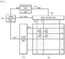
- FIG. 3 is a diagram illustrating an organic light emitting diode display device according to an embodiment of the present disclosure.
- the organic light emitting diode display device includes a display panel 100 , a gate driving unit 110 , a data driving unit 120 , a compensation data processing unit 140 , and a timing control unit 150 .
- the display panel 100 includes a plurality of gate lines GL and a plurality of data lines DL which intersect with each other, and a plurality of pixels P, each of which is disposed at every intersection of the respective gate lines GL and the respective data lines DL. Further, referring to FIG. 1 , each of the plurality of pixels P includes a switching transistor T sw , a driving transistor T dr , an organic light emitting diode EL, and a capacitor C st .
- the present disclosure is not limited thereto and the plurality of pixels P may be arranged in arrays of one or higher dimensions.
- the gate driving unit 110 sequentially supplies a scan signal S can to each of the gate lines GL.
- the gate driving unit 110 may be disposed externally from the display panel 100 or embedded in the display panel 100 in a gate-in-panel manner.
- the data driving unit 120 supplies a data voltage V data to the data lines DL, and senses a sink current flowing at each of the data lines DL to generate compensation data data corresponding to the sink current. Further, a data compensation circuit (not shown) to which an external compensation algorithm is applied may be embedded in the data driving unit 120 to generate the compensation data data.
- the compensation data processing unit 140 quantizes, compresses, and stores the compensation data data generated by the data driving unit 120 . Further, the compensation data processing unit 140 inverse quantizes and restores the stored compensation data data to supply the restored compensation data data to the timing control unit 150 . More particularly, the compensation data processing unit 140 may generate a quantization grid, to which a quantization step value is assigned, at positions corresponding to each of the pixels P. Further, the compensation data processing unit 140 may quantize and compress the compensation data data by assigning the quantization step value thereto using a quantization function that is determined according to a predetermined parameter, and an array dimension of the quantization grid. Such a compensation data processing unit 140 may be embedded in the organic light emitting diode display device separately from the timing control unit 150 .
- the compensation data data may be compressed through a data compression method, which will be described, according to an embodiment of the present disclosure.
- the timing control unit 150 reflects the restored compensation data data′ in image data RGB that is input from an external source. Further, the timing control unit 150 suitably aligns the image data RGB with a size, a resolution, and the like, of the display panel 100 , to supply the aligned image data RGB to the data driving unit 120 .
- the timing control unit 150 generates a plurality of gate control signals GCS and a plurality of data control signals DCS using synchronous signals that are input from an external source. Further, the timing control unit 150 supplies the gate control signals GCS and the data control signals DCS to the gate driving unit 110 and the data driving unit 120 , respectively.
- FIG. 4 is a detailed block diagram of a compensation data processing unit according to an embodiment of the present disclosure.
- a compensation data processing unit 140 includes a grid generation unit 141 , a sparse quantization unit 142 , an encoder 143 , a memory 144 , and a decoder 145 , and compresses the compensation data data that is assigned to a plurality of pixels arranged in an n dimensional array, wherein n is a natural number equal to or greater than 1.
- the compensation data processing unit 140 quantizes and compresses the compensation data data generated by the data driving unit 120 to store the compressed compensation data data in the memory 144 . Further, the compensation data processing unit 140 inverse quantizes and restores the stored compensation data data stored in the memory 144 to supply the restored compensation data data to the timing control unit 150 .
- the grid generation unit 141 generates a quantization grid, to which a quantization step value is assigned, at positions that correspond to positions of each of a plurality of pixels.
- a conformation of the quantization grid is determined according to an array dimension with which the plurality of pixels is provided.
- the quantization grid is also arranged in an n dimensional conformation, wherein n is a natural number equal to or greater than 1.
- the sparse quantization unit 142 assigns a quantization step value to the quantization grid using a preset quantization parameter and a quantization function that is determined according to an array dimension.
- the sparse quantization unit 142 quantizes compensation data, which is assigned to a pixel that is located at a position corresponding to a position of the quantization step value, using the quantization step value.
- a first quantization step value is assigned to the quantization grid at each of positions thereon in a regular interval in at least one direction, and a second quantization step value is assigned to each of the remaining positions on the quantization grid.
- a quantization parameter includes an interval parameter. Further, a first quantization step value is assigned to the quantization grid at each of positions thereon in an interval corresponding to the interval parameter, and a second quantization step value is assigned to each of the remaining positions on the quantization grid.
- the quantization parameter includes a horizontal interval parameter and a vertical interval parameter. Further, the first quantization step value is assigned to the quantization grid at each of positions thereon in an interval corresponding to the horizontal interval parameter and the vertical interval parameter, and the second quantization step value is assigned to each of the remaining positions on the quantization grid.
- the quantization parameter includes the horizontal interval parameter, the vertical interval parameter, and a horizontal shift parameter.
- the first quantization step value is assigned to the quantization grid at each of positions thereon in an interval corresponding to the horizontal interval parameter in which the horizontal shift parameter is reflected and the vertical interval parameter, and the second quantization step value is assigned to each of the remaining positions on the quantization grid.
- the quantization parameter includes the horizontal interval parameter, the vertical interval parameter, and a depth interval parameter. Further, the quantization step value is assigned to the quantization grid at each of positions thereon in an interval corresponding to the horizontal interval parameter, the vertical interval parameter, and the depth interval parameter, and the second quantization step value is assigned to each of the remaining positions on the quantization grid.
- the quantization parameter includes the horizontal interval parameter, the vertical interval parameter, the horizontal shift parameter, and the depth interval parameter.
- the first quantization step value is assigned to the quantization grid at each of positions thereon in an interval corresponding to the horizontal interval parameter in which the horizontal shift parameter is reflected, the vertical interval parameter, and the depth interval parameter, and the second quantization step value is assigned to each of the remaining positions on the quantization grid.
- the quantization parameter includes the horizontal interval parameter, the vertical interval parameter, the horizontal shift parameter, the depth interval parameter, and a vertical shift parameter.
- the first quantization step value is assigned to the quantization grid at each of positions thereon in an interval corresponding to the horizontal interval parameter in which the horizontal shift parameter is reflected, the vertical interval parameter in which the vertical shift parameter is reflected, and the depth interval parameter, and the second quantization step value is assigned to each of the remaining positions on the quantization grid.
- the encoder 144 compresses the quantized compensation data data, and the decoder 145 inverse quantizes and restores the compressed compensation data data.
- quantization step values Q and Q-q may be set to two or more values that are different from each other. Further, when the compensation data data, which are assigned to the plurality of pixels P, are quantized using the quantization step values Q and Q-q that are different from each other, data losses of the compensation data data according to quantization are different from each other.
- the quantization step value is assigned to the quantization grid in a repetitive pattern using the quantization parameter and the quantization function such that it may prevent a data loss, which is caused according to compression of the compensation data data assigned to each of the plurality of pixels, from being concentrated on pixels that are located at specific positions. That is, a data loss due to quantization may be spatially distributed.
- a loss of the compensation data data is spatially distributed, a deviation of a threshold voltage of the driving transistor T dr is effectively compensated such that image quality of the organic light emitting diode display device may be improved.
- the data includes the above described compensation data.
- FIG. 5 is a flow chart of a data compression method according to an embodiment of the present disclosure.
- the data compression method compresses data assigned to each of a plurality of pixels that are arranged in an n dimensional array, wherein n is a natural number equal to or greater than 1. Further, the data compression method includes generating a quantization grid in Operation S 1 , assigning a quantization step value to the quantization grid in Operation S 2 , performing quantization using the quantization step value in Operation S 3 , and compressing quantized data in Operation S 4 .
- a quantization grid Grid in which a quantization step value is assigned to positions corresponding to positions of each of a plurality of pixels, is generated.
- a conformation of the quantization grid is determined according to an array dimension with which the plurality of pixels are provided.
- the quantization step value is assigned through a quantization function that is determined according to a preset quantization parameter and the array dimension.
- the quantization step value may be set to two or more values that are different from each other.
- the quantization according to the present disclosure may prevent a data loss due to compression of the data from being concentrated on pixels located at specific positions compared to that which quantizes data assigned to a plurality of pixels using the same quantization step values. That is, in accordance with the present disclosure, a data loss due to quantization may be spatially distributed.
- the quantization according to the present disclosure may reduce a needed capacity of a memory for storing compressed data compared to that which quantizes data assigned to a plurality of pixels using a quantization step value determined according to a characteristic of each data, such that costs for employing a large capacity memory may be reduced.
- FIG. 6 is a diagram illustrating a quantization grid arranged in a one dimensional array according to an embodiment of the present disclosure.
- a quantization grid Grid corresponding to the plurality of pixels P is also arranged in a one dimensional array.
- a quantization parameter includes a horizontal interval parameter SGQ hor .
- first and second quantization step values Q and Q-q are assigned to the quantization grid Grid at positions corresponding to positions of the plurality of pixels P.
- the first and second quantization step values Q and Q-q are determined using a preset horizontal interval parameter SGQ hor and a quantization function SG(i). Further, the first quantization step value Q is assigned to the quantization grid Grid at each of positions thereon in an interval corresponding to the horizontal interval parameter SGQ hor , and the second quantization step value Q-q is assigned to each of the remaining positions on the quantization grid Grid.
- the second quantization step value Q-q is assigned to the quantization grid Grid at each of positions thereon in an interval corresponding to the horizontal interval parameter SGQ hor
- the first quantization step value Q is assigned to each of the remaining positions on the quantization grid Grid.
- the quantization function SG(i) is defined by the following Equation 1.
- Equation 1 means that values of the quantization function SG(i) have 1 at a first position of the quantization grid Grid and at positions thereon in an interval of the horizontal interval parameter SGQ hor based on the first position, and have 0 at the remaining positions on the quantization grid Grid.
- the first quantization step value Q may be assigned to each of the positions at which the values of the quantization function SG(i) have 1, and the second quantization step value Q-q may be assigned to each of the remaining positions at which the first quantization step value Q is not assigned.
- the first quantization step value Q is marked with X
- the second quantization step value Q-q is marked with •.
- the first and second quantization step values Q and Q-q are determined by setting the array number of the quantization grid Grid to 14 and the horizontal interval parameter SGQ hor to 6.
- the quantization step values Q and Q-q are assigned to the 1-dimensional quantization grid Grid in a repetitive pattern using the quantization parameter SGQ hor and the quantization function SG(i). Consequently, the above method may prevent a data loss due to compression of the data, which is assigned to each of the plurality of pixels P arranged in a one dimensional array, from being concentrated on pixels P located at specific positions. That is, in accordance with the present disclosure, the data loss due to compression may be spatially distributed.
- repetitive pattern intervals of the quantization step values Q and Q-q are adjusted such that it may be possible to provide an optimum compression ratio of data, which is capable of minimizing a data loss. That is, a needed capacity of a memory for storing compressed data may be reduced such that costs for employing a large capacity memory may be reduced.
- FIGS. 7 and 8 are diagrams illustrating a quantization grid arranged in a two dimensional array according to an embodiment of the present disclosure.
- a quantization grid Grid corresponding to the plurality of pixels P is also arranged in a two dimensional array.
- a quantization parameter SGQ includes a horizontal interval parameter SGQ hor , a vertical interval parameter SGQ ver , and a horizontal shift parameter SGQ shft1 .
- first and second quantization step values Q and Q-q are assigned to the quantization grid Grid at positions thereon corresponding to positions of the plurality of pixels P.
- the first and second quantization step values Q and Q-q are determined based on a horizontal interval parameter SGQ hor , a vertical interval parameter SGQ ver , a horizontal shift parameter SGQ shft1 , which are preset, and a quantization function SG(i,j). Further, the first quantization step value Q is assigned to the quantization grid Grid at each of positions thereon in an interval corresponding to the horizontal interval parameter SGQ hor in which the horizontal shift parameter SGQ shft1 is reflected, and the vertical interval parameter SGQ ver , and the second quantization step value Q-q is assigned to each of the remaining positions on the quantization grid Grid.
- the quantization function SG(i,j) is defined by the following Equations 2 to 5.
- (j % SGQ ver ) ⁇ 0 means that the remainder is 0 when j is divided by the vertical interval parameter SGQ ver
- (i+shft1) % SGQ hor ⁇ 0 means that the remainder is 0 when (i+shft1) is divided by the horizontal interval parameter SGQ hor .
- a first quantization function Fh(SGQ h ,shft1,i) defines quantization step values Q and Q-q at x-axis positions
- a second quantization function Fv(SGQ ver ,j) defines quantization step values Q and Q-q at y-axis positions.
- a value shft1 of a first shift function is used to determine the first quantization function Fh(SGQ h ,shft1,i) and is given by a first shift function shft1(SGQ shft1 , SGQ ver , j).
- Equation 2 means that values of the quantization function SG(i,j) are given by multiplying a first quantization function Fh(SGQ hor ,shft1,i) by a second quantization function Fv(SGQ ver ,j).
- Equation 3 means that y-axis values among the values of the quantization function SG(i,j) have 1 at a first y-axis position on the quantization grid Grid and at positions thereon in an interval of the vertical interval parameter SGQ ver based on the first y-axis position, and have 0 at the remaining positions on the quantization grid Grid.
- Equation 4 means that x-axis values among the values of the quantization function SG(i,j) have 1 at a first x-axis position on the quantization grid Grid and at positions thereon in an interval of the horizontal interval parameter SGQ hor based on the first x-axis position, and have 0 at the remaining positions on the quantization grid Grid.
- Equation 5 means that 1, which is given by Equation 4, is shifted by an amount corresponding to the horizontal shift parameter SGQ shft1 in an interval corresponding to the vertical interval parameter SGQ ver . Such a shift is illustrated in FIG. 8 .
- the first quantization step value Q may be assigned to each of the positions at which the values of the quantization function SG(i) have 1, and the second quantization step value Q-q may be assigned to each of the remaining positions.
- the first quantization step value Q is marked with X
- the second quantization step value Q-q is marked with •.
- the first and second quantization step values Q and Q-q are determined by setting an x-axis array number of the quantization grid Grid to 11, a y-axis array number thereof to 7, the horizontal interval parameter SGQ hor to 4, the vertical interval parameter SGQ ver to 3, and the horizontal shift parameter SGQ shft1 to 0 or 2.
- FIG. 7 shows a case in which the horizontal shift parameter SGQ shft1 is 0, and FIG. 8 shows a case in which the horizontal shift parameter SGQ shft1 is not 0.
- Equation 5 since the horizontal shift parameter SGQ shft1 is 0, Equation 5 is not applied and the value shft1 of the first shift function of Equation 4 becomes 0.
- the value of the quantization function SG(i,j) becomes 1 at each of positions at which the value of the first quantization function Fh(SGQ hor ,shft1,i) and the value of the second quantization function Fv(SGQ ver ,j) are 1.
- the first quantization step value Q may be assigned to each of positions at which the value of the quantization function SG(i,j) is 1, and the second quantization step value Q-q may be assigned to each of the remaining positions.
- the first and second quantization step values Q and Q-q may be assigned to positions and values contrary to the above description.
- Equation 5 is applied unlike in FIG. 7 .
- the value of the quantization function SG(i,j) becomes 1 at each of positions at which the value of the first quantization function Fh(SGQ hor ,shft1,i) and the value of the second quantization function Fv(SGQ ver ,j) are 1.
- the first quantization step value Q may be assigned to each of positions at which the value of the quantization function SG(i,j) is 1, and the second quantization step value Q-q may be assigned to each of the remaining positions.
- the first and second quantization step values Q and Q-q may be assigned to positions and values contrary to the above description.
- the quantization grid Grid of FIG. 8 is shifted by an amount corresponding to the horizontal shift parameter SGQ shft1 in an interval corresponding to the vertical interval parameter SGQ ver . That is, a data loss due to the quantization may be spatially more distributed by an amount of the shifting.
- the quantization step values Q and Q-q are assigned to the quantization grid Grid in a repetitive pattern using the quantization parameters SGQ hor , SGQ ver , and SGQ shft1 , and the quantization function SG(i,j), such that it may be possible to prevent a data loss due to the compression of data, which is assigned to each of a plurality of pixels P arranged in a two dimensional array, from being concentrated on pixels P at specific concentrated positions. That is, in accordance with the present disclosure, the data loss due to the quantization may be spatially distributed.
- repetitive pattern intervals of the quantization step values Q and Q-q are adjusted such that it may be possible to provide an optimum compression ratio of data, which is capable of minimizing a data loss. That is, a needed capacity of a memory for storing the compressed data may be reduced such that costs for employing a large capacity memory may be reduced.
- FIG. 9 is a diagram illustrating a quantization grid arranged in a three dimensional array according to an embodiment of the present disclosure
- FIGS. 10(A), 11(A) , and 12 (A) are diagrams illustrating an x-z plane of FIG. 9
- FIGS. 10(B), 11(B) , and 12 (B) are diagrams illustrating a plane of which z is 0 of the x-y plane of FIG. 9
- FIGS. 10(C), 11(C) , and 12 (C) are diagrams illustrating a plane of which z is 3 of the x-y plane of FIG. 9 .
- a quantization grid Grid corresponding the plurality of pixels is also arranged in a three dimensional array.
- a quantization parameter SGQ includes a horizontal interval parameter SGQ hor , a vertical interval parameter SGQ ver , a horizontal shift parameter SGQ shft1 , a vertical shift parameter SGQ shft2 and a depth interval parameter SGQ dep .
- first and second quantization step values Q and Q-q are assigned to the quantization grid Grid at positions thereon corresponding to the plurality of pixels.
- the first and second quantization step values Q and Q-q are determined using a horizontal interval parameter SGQ hor , a vertical interval parameter SGQ ver , a horizontal shift parameter SGQ shft1 , a vertical shift parameter SGQ shft2 , and a depth interval parameter SGQ dep , which are preset, and a quantization function SG(i,j,z).
- the first quantization step value Q is assigned to the quantization grid Grid at each of positions thereon in an interval corresponding to the horizontal interval parameter SGQ hor in which the horizontal shift parameter SGQ shft1 is reflected, the vertical interval parameter SGQ ver in which the vertical shift parameter SGQ shft2 is reflected, and the depth interval parameter SGQ dep , and the second quantization step value Q-q is assigned to each of the remaining positions on the quantization grid Grid.
- the quantization function SG(i,j,z) is defined by the following Equations 6 to 11.
- (z % SGQ dep ) ⁇ 0 means that the remainder is 0 when z is divided by the depth interval parameter SGQ dep
- (j+shft2)% SGQ ver ⁇ 0 means that the remainder is 0 when (j+shft2) is divided by the vertical interval parameter SGQ ver
- (i+shft1)% SGQ hor ⁇ 0 means that the remainder is 0 when (i+shft1) is divided by the horizontal interval parameter SGQ hor .
- a first quantization function Fh(SGQ hor ,shft1,i) defines a quantization step value at the x-axis position
- a second quantization function Fv(SGQ ver ,shft2,j) defines a quantization step value at the y-axis position
- a third quantization function Fd(SGQ dep ,z) defines a quantization step value at the z-axis position.
- a value shft1 of a first shift function is used to determine the first quantization function Fh(SGQ hor ,shft1,i) and is given by the first shift function shft1(SGQ shft1 ,SGQ ver ,j,shft2).
- a value shft2 of a second shift function is used to determine the second quantization function Fv(SGQ ver ,shft2,j), and is given by the second shift function shft2(SGQ shft2 ,SGQ dep ,z).
- Equation 6 means that values of the quantization function SG(i,j,z) are given by multiplying first quantization function Fh(SGQ h ,shft1,i), the second quantization function Fv(SGQ ver ,shft2,j), and the third quantization function Fd(SGQdep,z).
- Equation 7 means that z-axis values among the values of the quantization function SG(i,j,z) have 1 at a first z-axis position on the quantization grid Grid and at positions thereon in an interval corresponding the depth interval parameter SGQ dep based on the first z-axis position, and have 0 at the remaining positions on the quantization grid Grid.
- Equation 8 means that y-axis values among the values of the quantization function SG(i,j,z) have 1 at a first y-axis position on the quantization grid Grid and at positions thereon in an interval corresponding the vertical interval parameter SGQ ver based on the first y-axis position, and have 0 at the remaining positions on the quantization grid Grid.
- Equation 9 means that 1, which is given by Equation 8, is shifted by an amount corresponding to the vertical shift parameter SGQ shft2 in an interval corresponding to the depth interval parameter SGQ dep .
- Equation 10 means that x-axis values among the values of the quantization function SG(i,j,z) have 1 at a first x-axis position on the quantization grid Grid and at positions thereon in an interval corresponding the horizontal interval parameter SGQ hor based on the first x-axis position, and have 0 at the remaining positions on the quantization grid Grid.
- Equation 11 means that 1, which is given by Equation 10, is shifted by an amount corresponding to the horizontal shift parameter SGQ shft1 in an interval corresponding to the vertical interval parameter SGQ ver .
- the first quantization step value Q may be assigned to each of positions at which the value of the quantization function SG(i,j,z) is 1, and the second quantization step value Q-q may be assigned to each of the remaining positions.
- the first quantization step value Q is marked with X
- the second quantization step value Q-q is marked with •.
- the first and second quantization step values Q and Q-q are determined by setting the x-axis array number of the quantization grid Grid to 11, the y-axis array number thereof to 7, the z-axis array number thereof to 7, the horizontal interval parameter SGQ hor to 4, the vertical interval parameter SGQ ver to 3, the depth interval parameter SGQ dep to 3, the horizontal shift parameter SGQ shft1 to or 2, and the vertical shift parameter SGQ shft2 to 0 or 2.
- FIGS. 10(A) to 10(C) show a case in which both the horizontal shift parameter SGQ shft1 and the vertical shift parameter SGQ shft2 are 0.
- FIGS. 11(A) to 11(C) show a case in which the horizontal shift parameter SGQ shft1 is not 0 and the vertical shift parameter SGQ shft2 is 0.
- FIGS. 12(A) to 12(C) show a case in which both the horizontal shift parameter SGQ shft1 and the vertical shift parameter SGQ shft2 are not 0.
- Equations 9 and 11 are not applied, and the value shft2 of the second shift function of Equation 0 and the value shft1 of the first shift function of Equation 11 become 0.
- the value of the quantization function SG(i,j,z) becomes 1 at each of positions at which all the values of the first quantization function Fh(SGQ hor ,shft1,i), the second quantization function Fv(SGQ ver ,shft2,j), and the third quantization function Fd(SGQ dep ,z) are 1.
- the first quantization step value Q may be assigned to each of positions at which the values of the quantization function SG(i,j,z) have 1, and the second quantization step value Q-q may be assigned to each of the remaining positions.
- the first and second quantization step values Q and Q-q may be assigned to positions and values contrary to the above description.
- Equation 11 is applied.
- the value of the quantization function SG(i,j,z) becomes 1 at each of positions at which all the values of the first quantization function Fh(SGQ hor ,shft1,i), second quantization function Fv(SGQ ver ,shft2,j), and the third quantization function Fd(SGQ dep ,z) are 1.
- the first quantization step value Q may be assigned to each of positions at which the values of the quantization function SG(i,j,z) have 1, and the second quantization step value Q-q may be assigned to each of the remaining positions.
- the first and second quantization step values Q and Q-q may be assigned to positions and values contrary to the above description.
- the quantization grids Grid of FIGS. 11(A) to 11(C) are shifted by an amount corresponding to the horizontal shift parameter SGQ shft1 in an interval corresponding to the vertical interval parameter SGQ ver compared to the quantization grids Grid of FIGS. 10(A) to 10(C) . That is, a data loss due to the quantization may be spatially more distributed by an amount of the shifting.
- Equations 9 and 10 are applied.
- the value of the quantization function SG(i,j,z) becomes 1 at each of positions at which all the values of the first quantization function Fh(SGQ hor ,shft1,i), second quantization function Fv(SGQ ver ,shft2,j), and the third quantization function Fd(SGQ dep ,z) are 1.
- the first quantization step value Q may be assigned to each of positions at which the values of the quantization function SG(i,j,z) have 1, and the second quantization step value Q-q may be assigned to each of the remaining positions.
- the first and second quantization step values Q and Q-q may be assigned to positions and values contrary to the above description.
- the quantization grids Grid of FIGS. 12(A) to 12(C) are shifted by an amount corresponding to the vertical shift parameter SGQ shft2 in an interval corresponding to depth interval parameter SGQ dep compared to the quantization grids Grid of FIGS. 11(A) to 11(C) . That is, a data loss due to the quantization may be spatially more distributed by an amount of the shifting.
- the quantization step values Q and Q-q are assigned to the quantization grid Grid in a repetitive pattern using the quantization parameters SGQ hor , SGQ ver , SGQ dep , SGQ shft1 , and SGQ shft2 , and the quantization function SG(i,j,z), such that it may be possible to prevent a data loss due to the compression of data, which is assigned to each of a plurality of pixels P arranged in a three dimensional array, from being concentrated on pixels P of specific positions. That is, in accordance with the present disclosure, the data loss due to the quantization may be spatially distributed.
- repetitive pattern intervals of the quantization step values are adjusted such that it may be possible to provide an optimum compression ratio of data, which is capable of minimizing a data loss. That is, a capacity of a memory for storing the compressed data may be reduced such that costs for employing a large capacity memory may be reduced.
Landscapes
- Engineering & Computer Science (AREA)
- Multimedia (AREA)
- Signal Processing (AREA)
- Physics & Mathematics (AREA)
- Computer Hardware Design (AREA)
- General Physics & Mathematics (AREA)
- Theoretical Computer Science (AREA)
- Control Of Indicators Other Than Cathode Ray Tubes (AREA)
- Control Of El Displays (AREA)
- Financial Or Insurance-Related Operations Such As Payment And Settlement (AREA)
Abstract
Description
Claims (10)
Applications Claiming Priority (2)
| Application Number | Priority Date | Filing Date | Title |
|---|---|---|---|
| KR10-2016-0067224 | 2016-05-31 | ||
| KR1020160067224A KR102601350B1 (en) | 2016-05-31 | 2016-05-31 | Method For Compressing Data And Display Device Using The Same |
Publications (2)
| Publication Number | Publication Date |
|---|---|
| US20170347098A1 US20170347098A1 (en) | 2017-11-30 |
| US10602144B2 true US10602144B2 (en) | 2020-03-24 |
Family
ID=57956151
Family Applications (1)
| Application Number | Title | Priority Date | Filing Date |
|---|---|---|---|
| US15/404,975 Active 2037-04-08 US10602144B2 (en) | 2016-05-31 | 2017-01-12 | Method for compressing data and display device using the same |
Country Status (4)
| Country | Link |
|---|---|
| US (1) | US10602144B2 (en) |
| EP (1) | EP3252748B1 (en) |
| KR (1) | KR102601350B1 (en) |
| CN (1) | CN107454404B (en) |
Families Citing this family (6)
| Publication number | Priority date | Publication date | Assignee | Title |
|---|---|---|---|---|
| CN107610643B (en) * | 2017-09-29 | 2020-11-10 | 京东方科技集团股份有限公司 | Compensation circuit and control method thereof, display panel and display device |
| US10860399B2 (en) * | 2018-03-15 | 2020-12-08 | Samsung Display Co., Ltd. | Permutation based stress profile compression |
| US10593257B2 (en) | 2018-03-15 | 2020-03-17 | Samsung Display Co., Ltd. | Stress profile compression |
| CN108877740B (en) * | 2018-07-25 | 2020-09-22 | 昆山国显光电有限公司 | Method and device for acquiring Mura compensation data, computer equipment and storage medium |
| CN109887456A (en) * | 2019-01-17 | 2019-06-14 | 硅谷数模半导体(北京)有限公司 | Data compression method and apparatus |
| US11132944B2 (en) | 2019-09-18 | 2021-09-28 | Samsung Display Co., Ltd. | Unbiased iterative compression on additive data using dither |
Citations (16)
| Publication number | Priority date | Publication date | Assignee | Title |
|---|---|---|---|---|
| US5805914A (en) * | 1993-06-24 | 1998-09-08 | Discovision Associates | Data pipeline system and data encoding method |
| US20040151253A1 (en) * | 2002-09-26 | 2004-08-05 | Bossen Frank Jan | Low complexity and unified transforms for video coding |
| CN1650328A (en) | 2002-05-06 | 2005-08-03 | 皇家飞利浦电子股份有限公司 | System for and method of sharpness enhancement for coded digital video |
| US20080068293A1 (en) | 2006-09-19 | 2008-03-20 | Tvia, Inc. | Display Uniformity Correction Method and System |
| US20090040414A1 (en) * | 2004-02-09 | 2009-02-12 | Genshiro Kawachi | Liquid crystal pixel memory, liquid crystal display, and methods of driving the same |
| US20090147843A1 (en) * | 2007-12-11 | 2009-06-11 | Samsung Electronics Co., Ltd. | Method and apparatus for quantization, and method and apparatus for inverse quantization |
| US20090257664A1 (en) * | 2006-11-08 | 2009-10-15 | Meng-Ping Kao | Methods and apparatus for in -loop de-artifact filtering |
| CN101714327A (en) | 2008-10-07 | 2010-05-26 | 索尼株式会社 | display device |
| US20110116723A1 (en) * | 2008-05-27 | 2011-05-19 | Jim Rasmusson | Index-Based Pixel Block Processing |
| CN102123276A (en) | 2009-12-15 | 2011-07-13 | 铜陵市维新投资咨询有限公司 | Code rate control method during scene change |
| US20120121012A1 (en) * | 2009-07-27 | 2012-05-17 | Kabushiki Kaisha Toshiba | Image coding method and image decoding method |
| US20130272390A1 (en) * | 2012-04-16 | 2013-10-17 | Qualcomm Incorporated | Uniform granularity for quantization matrix in video coding |
| CN104751794A (en) | 2013-12-31 | 2015-07-01 | 乐金显示有限公司 | Organic light emitting display device and driving method thereof |
| CN104919517A (en) | 2013-01-21 | 2015-09-16 | 夏普株式会社 | Display device and data processing method of display device |
| KR20160010163A (en) | 2014-07-18 | 2016-01-27 | 엘지디스플레이 주식회사 | Organic light emmitting diode device and threshold voltage compensation data processing method of organic light emmitting diode device thereof |
| CN105304020A (en) | 2015-11-23 | 2016-02-03 | 武汉天马微电子有限公司 | Organic light emitting diode pixel drive circuit, array substrate and display device |
Family Cites Families (3)
| Publication number | Priority date | Publication date | Assignee | Title |
|---|---|---|---|---|
| US7590299B2 (en) * | 2004-06-10 | 2009-09-15 | Samsung Electronics Co., Ltd. | Increasing gamma accuracy in quantized systems |
| EP2357640A1 (en) * | 2009-12-02 | 2011-08-17 | Koninklijke Philips Electronics N.V. | Luminance control for pixels of a display panel |
| CN103327259B (en) * | 2013-07-19 | 2016-03-23 | 西安诺瓦电子科技有限公司 | The parameter regulation means of LED display correction camera and device |
-
2016
- 2016-05-31 KR KR1020160067224A patent/KR102601350B1/en active Active
-
2017
- 2017-01-12 US US15/404,975 patent/US10602144B2/en active Active
- 2017-01-16 CN CN201710028430.8A patent/CN107454404B/en active Active
- 2017-01-31 EP EP17154048.7A patent/EP3252748B1/en active Active
Patent Citations (18)
| Publication number | Priority date | Publication date | Assignee | Title |
|---|---|---|---|---|
| US5805914A (en) * | 1993-06-24 | 1998-09-08 | Discovision Associates | Data pipeline system and data encoding method |
| CN1650328A (en) | 2002-05-06 | 2005-08-03 | 皇家飞利浦电子股份有限公司 | System for and method of sharpness enhancement for coded digital video |
| US20040151253A1 (en) * | 2002-09-26 | 2004-08-05 | Bossen Frank Jan | Low complexity and unified transforms for video coding |
| US20090040414A1 (en) * | 2004-02-09 | 2009-02-12 | Genshiro Kawachi | Liquid crystal pixel memory, liquid crystal display, and methods of driving the same |
| US20080068293A1 (en) | 2006-09-19 | 2008-03-20 | Tvia, Inc. | Display Uniformity Correction Method and System |
| US20090257664A1 (en) * | 2006-11-08 | 2009-10-15 | Meng-Ping Kao | Methods and apparatus for in -loop de-artifact filtering |
| US20090147843A1 (en) * | 2007-12-11 | 2009-06-11 | Samsung Electronics Co., Ltd. | Method and apparatus for quantization, and method and apparatus for inverse quantization |
| US20110116723A1 (en) * | 2008-05-27 | 2011-05-19 | Jim Rasmusson | Index-Based Pixel Block Processing |
| CN101714327A (en) | 2008-10-07 | 2010-05-26 | 索尼株式会社 | display device |
| US20120121012A1 (en) * | 2009-07-27 | 2012-05-17 | Kabushiki Kaisha Toshiba | Image coding method and image decoding method |
| CN102123276A (en) | 2009-12-15 | 2011-07-13 | 铜陵市维新投资咨询有限公司 | Code rate control method during scene change |
| US20130272390A1 (en) * | 2012-04-16 | 2013-10-17 | Qualcomm Incorporated | Uniform granularity for quantization matrix in video coding |
| CN104919517A (en) | 2013-01-21 | 2015-09-16 | 夏普株式会社 | Display device and data processing method of display device |
| US20150356899A1 (en) * | 2013-01-21 | 2015-12-10 | Sharp Kabushiki Kaisha | Display device, and data processing method in display device |
| CN104751794A (en) | 2013-12-31 | 2015-07-01 | 乐金显示有限公司 | Organic light emitting display device and driving method thereof |
| US20150187328A1 (en) | 2013-12-31 | 2015-07-02 | Lg Display Co., Ltd. | Organic light emitting display device and driving method thereof |
| KR20160010163A (en) | 2014-07-18 | 2016-01-27 | 엘지디스플레이 주식회사 | Organic light emmitting diode device and threshold voltage compensation data processing method of organic light emmitting diode device thereof |
| CN105304020A (en) | 2015-11-23 | 2016-02-03 | 武汉天马微电子有限公司 | Organic light emitting diode pixel drive circuit, array substrate and display device |
Also Published As
| Publication number | Publication date |
|---|---|
| KR20170136101A (en) | 2017-12-11 |
| CN107454404B (en) | 2020-09-11 |
| US20170347098A1 (en) | 2017-11-30 |
| KR102601350B1 (en) | 2023-11-13 |
| EP3252748A1 (en) | 2017-12-06 |
| EP3252748B1 (en) | 2019-02-27 |
| CN107454404A (en) | 2017-12-08 |
Similar Documents
| Publication | Publication Date | Title |
|---|---|---|
| US10602144B2 (en) | Method for compressing data and display device using the same | |
| US9773455B2 (en) | Organic light emitting display device for compensation of pixel degradation and driving method thereof | |
| US8456414B2 (en) | Gamma adjustment with error diffusion for electrophoretic displays | |
| US9159258B2 (en) | Display device, and optical compensation system and optical compensation method thereof | |
| US20070273701A1 (en) | Display apparatus | |
| US10600359B2 (en) | Organic light emitting display apparatus using dithering and method of driving the same | |
| JP6661285B2 (en) | Display panel, method of compensating pixel luminance of display panel and method of compensating pixel parameters | |
| KR20150057405A (en) | Display driving device and display device including the same | |
| KR102764002B1 (en) | Method and system of stress compensation in display device | |
| KR20200050332A (en) | Display, method of stress compensation in display, and system | |
| KR102581838B1 (en) | Method For Processing Compensation Data And Organic Light Emitting Diode Display Device Using The Same | |
| US11282431B2 (en) | System and method for display compensation | |
| US10200685B2 (en) | Method for compressing data and organic light emitting diode display device using the same | |
| KR102159011B1 (en) | Organic light emmitting diode device and threshold voltage compensation data processing method of organic light emmitting diode device thereof | |
| KR102622956B1 (en) | Device and Method For Processing Compensation Data And Organic Light Emitting Diode Display Device Using The Same | |
| KR102857692B1 (en) | Display device and method for controlling brightness using quaternary-tree thereof | |
| KR20180042883A (en) | Organic light emitting display device and driving method thereof | |
| KR102660176B1 (en) | Accumulated data generator and display device | |
| CN111787331B (en) | Display data compression method, compression device and display device | |
| KR20160083573A (en) | Image Processing Method And Apparatus And Display Device Including The Same | |
| KR102896902B1 (en) | Display and method for controlling brightness using middle value and linear interpolation thereof | |
| KR102024654B1 (en) | Display apparatus and method for driving digital pixel of the same | |
| KR102508761B1 (en) | Organic light emitting display and driving method for the same |
Legal Events
| Date | Code | Title | Description |
|---|---|---|---|
| AS | Assignment |
Owner name: SAINT-PETERSBURG STATE UNIVERSITY OF AEROSPACE INSTRUMENTATION, RUSSIAN FEDERATION Free format text: ASSIGNMENT OF ASSIGNORS INTEREST;ASSIGNORS:GILMUTDINOV, MARAT;OH, EUIYEOL;LEE, CHULKWON;AND OTHERS;SIGNING DATES FROM 20161228 TO 20161229;REEL/FRAME:040964/0102 Owner name: LG DISPLAY CO., LTD., KOREA, REPUBLIC OF Free format text: ASSIGNMENT OF ASSIGNORS INTEREST;ASSIGNORS:GILMUTDINOV, MARAT;OH, EUIYEOL;LEE, CHULKWON;AND OTHERS;SIGNING DATES FROM 20161228 TO 20161229;REEL/FRAME:040964/0102 Owner name: SAINT-PETERSBURG STATE UNIVERSITY OF AEROSPACE INS Free format text: ASSIGNMENT OF ASSIGNORS INTEREST;ASSIGNORS:GILMUTDINOV, MARAT;OH, EUIYEOL;LEE, CHULKWON;AND OTHERS;SIGNING DATES FROM 20161228 TO 20161229;REEL/FRAME:040964/0102 |
|
| STPP | Information on status: patent application and granting procedure in general |
Free format text: ADVISORY ACTION MAILED |
|
| STPP | Information on status: patent application and granting procedure in general |
Free format text: DOCKETED NEW CASE - READY FOR EXAMINATION |
|
| STPP | Information on status: patent application and granting procedure in general |
Free format text: NON FINAL ACTION MAILED |
|
| STPP | Information on status: patent application and granting procedure in general |
Free format text: RESPONSE TO NON-FINAL OFFICE ACTION ENTERED AND FORWARDED TO EXAMINER |
|
| STPP | Information on status: patent application and granting procedure in general |
Free format text: NOTICE OF ALLOWANCE MAILED -- APPLICATION RECEIVED IN OFFICE OF PUBLICATIONS |
|
| STPP | Information on status: patent application and granting procedure in general |
Free format text: PUBLICATIONS -- ISSUE FEE PAYMENT VERIFIED |
|
| STCF | Information on status: patent grant |
Free format text: PATENTED CASE |
|
| MAFP | Maintenance fee payment |
Free format text: PAYMENT OF MAINTENANCE FEE, 4TH YEAR, LARGE ENTITY (ORIGINAL EVENT CODE: M1551); ENTITY STATUS OF PATENT OWNER: LARGE ENTITY Year of fee payment: 4 |