US10600650B2 - Semiconductor device and manufacture thereof - Google Patents
Semiconductor device and manufacture thereof Download PDFInfo
- Publication number
- US10600650B2 US10600650B2 US15/964,447 US201815964447A US10600650B2 US 10600650 B2 US10600650 B2 US 10600650B2 US 201815964447 A US201815964447 A US 201815964447A US 10600650 B2 US10600650 B2 US 10600650B2
- Authority
- US
- United States
- Prior art keywords
- connection component
- contact
- layer
- dopant
- region
- Prior art date
- Legal status (The legal status is an assumption and is not a legal conclusion. Google has not performed a legal analysis and makes no representation as to the accuracy of the status listed.)
- Active
Links
Images


Classifications
-
- H—ELECTRICITY
- H10—SEMICONDUCTOR DEVICES; ELECTRIC SOLID-STATE DEVICES NOT OTHERWISE PROVIDED FOR
- H10P—GENERIC PROCESSES OR APPARATUS FOR THE MANUFACTURE OR TREATMENT OF DEVICES COVERED BY CLASS H10
- H10P30/00—Ion implantation into wafers, substrates or parts of devices
- H10P30/20—Ion implantation into wafers, substrates or parts of devices into semiconductor materials, e.g. for doping
-
- H01L21/0465—
-
- H—ELECTRICITY
- H10—SEMICONDUCTOR DEVICES; ELECTRIC SOLID-STATE DEVICES NOT OTHERWISE PROVIDED FOR
- H10P—GENERIC PROCESSES OR APPARATUS FOR THE MANUFACTURE OR TREATMENT OF DEVICES COVERED BY CLASS H10
- H10P30/00—Ion implantation into wafers, substrates or parts of devices
- H10P30/20—Ion implantation into wafers, substrates or parts of devices into semiconductor materials, e.g. for doping
- H10P30/22—Ion implantation into wafers, substrates or parts of devices into semiconductor materials, e.g. for doping using masks
-
- H01L21/0455—
-
- H01L21/266—
-
- H01L21/2822—
-
- H01L21/31155—
-
- H01L21/74—
-
- H01L29/0623—
-
- H—ELECTRICITY
- H10—SEMICONDUCTOR DEVICES; ELECTRIC SOLID-STATE DEVICES NOT OTHERWISE PROVIDED FOR
- H10D—INORGANIC ELECTRIC SEMICONDUCTOR DEVICES
- H10D62/00—Semiconductor bodies, or regions thereof, of devices having potential barriers
- H10D62/10—Shapes, relative sizes or dispositions of the regions of the semiconductor bodies; Shapes of the semiconductor bodies
- H10D62/102—Constructional design considerations for preventing surface leakage or controlling electric field concentration
- H10D62/103—Constructional design considerations for preventing surface leakage or controlling electric field concentration for increasing or controlling the breakdown voltage of reverse-biased devices
- H10D62/105—Constructional design considerations for preventing surface leakage or controlling electric field concentration for increasing or controlling the breakdown voltage of reverse-biased devices by having particular doping profiles, shapes or arrangements of PN junctions; by having supplementary regions, e.g. junction termination extension [JTE]
- H10D62/106—Constructional design considerations for preventing surface leakage or controlling electric field concentration for increasing or controlling the breakdown voltage of reverse-biased devices by having particular doping profiles, shapes or arrangements of PN junctions; by having supplementary regions, e.g. junction termination extension [JTE] having supplementary regions doped oppositely to or in rectifying contact with regions of the semiconductor bodies, e.g. guard rings with PN or Schottky junctions
- H10D62/107—Buried supplementary regions, e.g. buried guard rings
-
- H—ELECTRICITY
- H10—SEMICONDUCTOR DEVICES; ELECTRIC SOLID-STATE DEVICES NOT OTHERWISE PROVIDED FOR
- H10D—INORGANIC ELECTRIC SEMICONDUCTOR DEVICES
- H10D62/00—Semiconductor bodies, or regions thereof, of devices having potential barriers
- H10D62/10—Shapes, relative sizes or dispositions of the regions of the semiconductor bodies; Shapes of the semiconductor bodies
- H10D62/113—Isolations within a component, i.e. internal isolations
-
- H—ELECTRICITY
- H10—SEMICONDUCTOR DEVICES; ELECTRIC SOLID-STATE DEVICES NOT OTHERWISE PROVIDED FOR
- H10D—INORGANIC ELECTRIC SEMICONDUCTOR DEVICES
- H10D64/00—Electrodes of devices having potential barriers
- H10D64/01—Manufacture or treatment
- H10D64/013—Manufacture or treatment of electrodes having a conductor capacitively coupled to a semiconductor by an insulator
- H10D64/01302—Manufacture or treatment of electrodes having a conductor capacitively coupled to a semiconductor by an insulator the insulator being formed after the semiconductor body, the semiconductor being silicon
- H10D64/01332—Making the insulator
- H10D64/01348—Making the insulator with substrate doping, e.g. N, Ge or C implantation, before formation of the insulator
-
- H—ELECTRICITY
- H10—SEMICONDUCTOR DEVICES; ELECTRIC SOLID-STATE DEVICES NOT OTHERWISE PROVIDED FOR
- H10P—GENERIC PROCESSES OR APPARATUS FOR THE MANUFACTURE OR TREATMENT OF DEVICES COVERED BY CLASS H10
- H10P30/00—Ion implantation into wafers, substrates or parts of devices
- H10P30/40—Ion implantation into wafers, substrates or parts of devices into insulating materials
-
- H—ELECTRICITY
- H10—SEMICONDUCTOR DEVICES; ELECTRIC SOLID-STATE DEVICES NOT OTHERWISE PROVIDED FOR
- H10P—GENERIC PROCESSES OR APPARATUS FOR THE MANUFACTURE OR TREATMENT OF DEVICES COVERED BY CLASS H10
- H10P32/00—Diffusion of dopants within, into or out of wafers, substrates or parts of devices
- H10P32/10—Diffusion of dopants within, into or out of semiconductor bodies or layers
- H10P32/17—Diffusion of dopants within, into or out of semiconductor bodies or layers characterised by the semiconductor material
- H10P32/171—Diffusion of dopants within, into or out of semiconductor bodies or layers characterised by the semiconductor material being group IV material
- H10P32/172—Diffusion of dopants within, into or out of semiconductor bodies or layers characterised by the semiconductor material being group IV material being crystalline silicon carbide
-
- H—ELECTRICITY
- H10—SEMICONDUCTOR DEVICES; ELECTRIC SOLID-STATE DEVICES NOT OTHERWISE PROVIDED FOR
- H10P—GENERIC PROCESSES OR APPARATUS FOR THE MANUFACTURE OR TREATMENT OF DEVICES COVERED BY CLASS H10
- H10P32/00—Diffusion of dopants within, into or out of wafers, substrates or parts of devices
- H10P32/20—Diffusion for doping of insulating layers
-
- H—ELECTRICITY
- H10—SEMICONDUCTOR DEVICES; ELECTRIC SOLID-STATE DEVICES NOT OTHERWISE PROVIDED FOR
- H10W—GENERIC PACKAGES, INTERCONNECTIONS, CONNECTORS OR OTHER CONSTRUCTIONAL DETAILS OF DEVICES COVERED BY CLASS H10
- H10W15/00—Highly-doped buried regions of integrated devices
-
- H—ELECTRICITY
- H10—SEMICONDUCTOR DEVICES; ELECTRIC SOLID-STATE DEVICES NOT OTHERWISE PROVIDED FOR
- H10W—GENERIC PACKAGES, INTERCONNECTIONS, CONNECTORS OR OTHER CONSTRUCTIONAL DETAILS OF DEVICES COVERED BY CLASS H10
- H10W15/00—Highly-doped buried regions of integrated devices
- H10W15/01—Manufacture or treatment
Definitions
- This inventive concept relates generally to semiconductor techniques, and more specifically, to a semiconductor device and its manufacturing method.
- a buried layer is frequently used to insulate a region above it from a region below it (e.g., to insulate a semiconductor layer above the buried layer from a substrate below it).
- the buried layer usually has a high doping concentration. If different buried layers need to be insulated from each other, they must maintain a relatively large inter-layer distance, which results in a large area budget of a substrate.
- this inventive concept proposes an innovative solution that reduces an area budget of a substrate and simplifies the manufacturing process.
- This inventive concept first presents a semiconductor device manufacturing method, comprising:
- the second ion implantation may form a first doped region underneath the first buried layer and a second doped region underneath the second buried layer in the substrate, with the first and the second doped regions both having the second conductive type.
- the aforementioned method may further comprise conducting an annealing process after the semiconductor layer is formed, and in the aforementioned method, the first and the second buried layers may both comprise a first dopant and a second dopant, with the second dopant having a lighter atomic weight than the first dopant, and the annealing process may cause at least a portion of the second dopant in the first and the second buried layers to diffuse to the semiconductor layer to form a first diffuse region on the first buried layer and a second diffuse region on the second buried layer in the semiconductor layer.
- the annealing process may cause at least a portion of a dopant in the separation region to diffuse to the semiconductor layer to form a third diffuse region on the separation region in the semiconductor layer.
- the aforementioned method may further comprise:
- first connection component extending from an upper surface of the semiconductor layer to the first diffuse region
- second connection component extending from the upper surface of the semiconductor layer to the second diffuse region
- connection component extending from the upper surface of the semiconductor layer to the third diffuse region, wherein the first and the second connection components both have the first conductive type and the third connection component has the second conductive type.
- forming a first connection component and a second connection component may comprise:
- forming a third connection component may comprise:
- the aforementioned method may further comprise:
- This inventive concept further presents another semiconductor device manufacturing method, comprising:
- first and the second buried layers are separated from each other, both have a first conductive type and both comprise a first dopant and a second dopant, with the second dopant having a lighter atomic weight than the first dopant;
- first connection component extending from an upper surface of the semiconductor layer to the first diffuse region
- second connection component extending from the upper surface of the semiconductor layer to the second diffuse region
- first and the second connection components both having the first conductive type
- forming a first connection component and a second connection component may comprise:
- this semiconductor device manufacturing method may further comprise:
- This inventive concept further presents a semiconductor device, comprising:
- a substrate comprising:
- first and the second buried layers both have a first conductive type, while the separation region, the first doped region, and the second doped region all have a second conductive type opposite to the first conductive type.
- the first and the second buried layers may both comprise a first dopant and a second dopant, with the second dopant having a lighter atomic weight than the first dopant,
- the semiconductor layer may comprise a first diffuse region on the first buried layer and a second diffuse region on the second buried layer, with the first and the second diffuse regions both comprising the second dopant.
- the semiconductor layer may further comprise a third diffuse region on the separation region.
- the aforementioned semiconductor device may further comprise:
- a first connection component extending from an upper surface of the semiconductor layer to the first diffuse region
- connection component extending from the upper surface of the semiconductor layer to the third diffuse region, wherein the first and the second connection components both have the first conductive type and the third connection component has the second conductive type.
- the aforementioned semiconductor device may further comprise:
- This inventive concept further presents yet another semiconductor device, comprising:
- a substrate comprising:
- a semiconductor layer on the substrate comprising a first diffuse region on the first buried layer and a second diffuse region on the second buried layer, with the first and the second diffuse regions both comprising the second dopant;
- connection component extending from the upper surface of the semiconductor layer to the second diffuse region, with the first and the second connection components both having the first conductive type.
- this semiconductor device may further comprise:
- FIG. 1 shows a simplified flowchart illustrating a semiconductor device manufacturing method in accordance with one embodiment of this inventive concept.
- FIGS. 2A, 2B, 2C, 2D, 2E, 2F, 2G and 2H show schematic sectional views illustrating different stages of a semiconductor device manufacturing method in accordance with one embodiment of this inventive concept.
- FIG. 3 shows a simplified flowchart illustrating a semiconductor device manufacturing method in accordance with another embodiment of this inventive concept.
- FIGS. 4A, 4B, 4C, 4D, 4E, 4F, and 4G show schematic sectional views illustrating different stages of a semiconductor device manufacturing method in accordance with another embodiment of this inventive concept.
- Embodiments in the figures may represent idealized illustrations. Variations from the shapes illustrated may be possible, for example due to manufacturing techniques and/or tolerances. Thus, the example embodiments shall not be construed as limited to the shapes or regions illustrated herein but are to include deviations in the shapes. For example, an etched region illustrated as a rectangle may have rounded or curved features. The shapes and regions illustrated in the figures are illustrative and shall not limit the scope of the embodiments.
- first,” “second,” etc. may be used herein to describe various elements, these elements shall not be limited by these terms. These terms may be used to distinguish one element from another element. Thus, a first element discussed below may be termed a second element without departing from the teachings of the present inventive concept. The description of an element as a “first” element may not require or imply the presence of a second element or other elements.
- the terms “first,” “second,” etc. may also be used herein to differentiate different categories or sets of elements. For conciseness, the terms “first,” “second,” etc. may represent “first-category (or first-set),” “second-category (or second-set),” etc., respectively.
- first element such as a layer, film, region, or substrate
- neighbored such as a layer, film, region, or substrate
- the first element can be directly on, directly neighboring, directly connected to or directly coupled with the second element, or an intervening element may also be present between the first element and the second element.
- first element is referred to as being “directly on,” “directly neighboring,” “directly connected to,” or “directly coupled with” a second element, then no intended intervening element (except environmental elements such as air) may also be present between the first element and the second element.
- spatially relative terms such as “beneath,” “below,” “lower,” “above,” “upper,” and the like, may be used herein for ease of description to describe one element or feature's spatial relationship to another element(s) or feature(s) as illustrated in the figures. It will be understood that the spatially relative terms may encompass different orientations of the device in use or operation in addition to the orientation depicted in the figures. For example, if the device in the figures is turned over, elements described as “below” or “beneath” other elements or features would then be oriented “above” the other elements or features. Thus, the term “below” can encompass both an orientation of above and below. The device may be otherwise oriented (rotated 90 degrees or at other orientation), and the spatially relative descriptors used herein shall be interpreted accordingly.
- connection may mean “electrically connect.”
- insulation may mean “electrically insulate.”
- Embodiments of the inventive concept may also cover an article of manufacture that includes a non-transitory computer readable medium on which computer-readable instructions for carrying out embodiments of the inventive technique are stored.
- the computer readable medium may include, for example, semiconductor, magnetic, opto-magnetic, optical, or other forms of computer readable medium for storing computer readable code.
- the inventive concept may also cover apparatuses for practicing embodiments of the inventive concept. Such apparatus may include circuits, dedicated and/or programmable, to carry out operations pertaining to embodiments of the inventive concept.
- Examples of such apparatus include a general purpose computer and/or a dedicated computing device when appropriately programmed and may include a combination of a computer/computing device and dedicated/programmable hardware circuits (such as electrical, mechanical, and/or optical circuits) adapted for the various operations pertaining to embodiments of the inventive concept.
- a general purpose computer and/or a dedicated computing device when appropriately programmed and may include a combination of a computer/computing device and dedicated/programmable hardware circuits (such as electrical, mechanical, and/or optical circuits) adapted for the various operations pertaining to embodiments of the inventive concept.
- FIG. 1 shows a simplified flowchart illustrating a semiconductor device manufacturing method in accordance with one embodiment of this inventive concept
- FIGS. 2A, 2B, 2C, 2D, 2E, 2F, 2G and 2H show schematic sectional views illustrating different stages of this semiconductor device manufacturing method. This semiconductor device manufacturing method is described below with reference to these drawings.
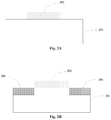
- a patterned first hard mask layer 202 is formed on a substrate 201 to define a position for buried layers, as shown in FIG. 2A .
- the substrate 201 may be a silicon substrate or a III-VI group semiconductor substrate, and the first hard mask layer 202 may be a photoresist.
- step 104 a first ion implantation using the first hard mask layer 202 as a mask is conducted to form a first buried layer 203 at a first side of the first hard mask layer 202 and a second buried layer 204 at a second side of the first hard mask layer 202 in the substrate 201 , the first and the second buried layers are separated from each other, as shown in FIG. 2B .
- the first buried layer 203 and the second buried layer 204 may both have a first conductive type (e.g., N-type), and both comprise a first dopant and a second dopant, with the second dopant having a lighter atomic weight than the first dopant.
- the first dopant may be antimony (Sb), which has a relatively large atomic weight
- the second dopant may be phosphorus (P), which has a relatively small atomic weight.
- the quantity of the first dopant may be larger than that of the second dopant.
- step 106 a second ion implantation is conducted to form a separation region 205 with a second conductive type between the first buried layer 203 and the second buried layer 204 in the substrate 201 , as shown in FIG. 2C .
- the second conductive type (e.g. P-type) may be opposite to the first conductive type.
- the energy for the second ion implantation is high enough to ensure the ions can penetrate the first hard mask layer 202 and reach the substrate 201 beneath.
- the separation region 205 formed in this process separates the first buried layer 203 and the second buried layer 204 .
- the second ion implantation when it has a sufficiently high energy, it may also form a first doped region 206 underneath the first buried layer 203 , and a second doped region 207 underneath the second buried layer 204 in the substrate 201 , with the first doped region 206 and the second doped region 207 both having the second conductive type.
- step 108 after the separation region 205 is formed, the first hard mask layer 202 is removed, as shown in FIG. 2D .
- a semiconductor layer 208 is formed on the substrate 201 , as shown in FIG. 2E .
- the semiconductor layer 208 may be formed on the first buried layer 203 , the second buried layer 204 , and the separation region 205 , and may be used for forming various semiconductor devices.
- the semiconductor layer 208 may be made of silicon or germanium, and may be formed by epitaxial growth.
- a separation region 205 is formed between the first and the second buried layers and has an opposite conductive type with the first and the second buried layers.
- the separation region 205 insulates the first buried layer from the second buried layer. This insulation allows a shorter inter-layer distance between the first and the second buried layers and, as a result, a smaller area budge of a substrate than that required by conventional methods.
- the second ion implantation (the ion implantation that forms the separation region) can be conducted without the first hard mask layer being removed, therefore the separation region may be formed by a single lithography process, which simplifies the manufacturing process.
- an annealing process may be conducted after the semiconductor layer 208 is formed, this process is described below with reference to FIGS. 2F, 2G and 2H .
- an annealing process is conducted. Since the first buried layer 203 and the second buried layer 204 comprise the first dopant and the second dopant, the annealing process causes at least a portion of the second dopant, which has a lighter atomic weight, to diffuse to the semiconductor layer 208 to form a first diffuse region 209 on the first buried layer 203 and a second diffuse region 210 on the second buried layer 204 in the semiconductor layer 208 . In another embodiment, the annealing process may also cause at least a portion of a dopant in the separation region 205 to diffuse to the semiconductor layer 208 to form a third diffuse region 211 on the separation region 205 in the semiconductor layer 208 .
- a first connection component 212 extends from an upper surface of the semiconductor layer 208 to the first diffuse region 209
- the second connection component 213 extends from the upper surface of the semiconductor layer 208 to the second diffuse region 210
- the third connection component 214 extends from the upper surface of the semiconductor layer 208 to the third diffuse region 211 .
- the first connection component 212 and the second connection component 213 both have the first conductive type, that is, they have the same conductive type as the first buried layer 203 , the second buried layer 204 , the first diffuse region 209 , and the second diffuse region 210 .
- the third connection component 214 has the second conductive type, that is, it has the same conductive type as the separation region 205 and the third diffuse region 211 .
- the first connection component 212 and the second connection component 213 may be formed through the following process: first, form a patterned second hard mask layer (not shown in the drawings) on the semiconductor layer 208 , with the second hard mask layer having a first opening and a second opening each exposing a portion of the semiconductor layer 208 ; then, conduct a third ion implantation to dope the portion of the semiconductor layer 208 underneath the first opening and the second opening to form the first connection component 212 and the second connection component 213 , respectively; then, remove the second hard mask layer.
- the third connection component 214 may be formed through the following process: first, form a patterned third hard mask layer (not shown in the drawings) on the semiconductor layer 208 , with the third hard mask layer having a third opening exposing a portion of the semiconductor layer 208 ; then, conduct a fourth ion implantation to dope the portion of the semiconductor layer 208 underneath the third opening to form the third connection component 214 ; then, remove the third hard mask layer.
- connection component 214 may be formed either before or after the first connection component 212 and the second connection component 213 are formed. The disclosure does not intend to limit the order in which these connection components may be formed.
- a first contact 215 may be formed in the first connection component 212 , and a first contact component 216 may be formed on the first contact 215 .
- a second contact 217 may be formed in the second connection component 213 , and a second contact component 218 may be formed on the second contact 217 ;
- a third contact 219 may be formed in the third connection component 214 , and
- a third contact component 220 may be formed on the third contact 219 .
- Electrical voltages may be applied on the first buried layer 203 , the second buried layer 204 , and the separation region 205 through the first contact component 216 , the second contact component 218 , and the third contact component 220 , respectively.
- Metal silicide may first be formed on each of the first contact 215 , the second contact 217 , and the third contact 219 , then the first contact component 216 , the second contact component 218 , and the third contact component 220 may be formed on the respective metal silicide.
- the first contact 215 , the second contact 217 , and the third contact 219 may be formed through ion implantation processes.
- the first contact 215 may have the first conductive type and have a doping concentration larger than that of the first connection component 212
- the second contact 217 may have the first conductive type and have a doping concentration larger than that of the second connection component 213
- the third contact 219 may have the second conductive type and have a doping concentration larger than that of the third connection component 214 .
- the space occupied by the first connection component 212 , the second connection component 213 , and the third connection component 214 should be kept at a minimum, that in turn requires the sizes of the first opening, the second opening, and the third opening remain as small as possible.
- the semiconductor layer 208 is thick, forming the first connection component 212 , the second connection component 213 , and the third connection component 214 conventionally requires a deep ion implantation process that can only be accomplished by sophisticated implantation equipment with relatively large sizes of the first, the second and the third openings.
- this inventive concept includes a two-dopant implantation process to form buried layers.
- this ion implantation process two dopants (one with a heavier atomic weight than the other) are implanted.
- the dopant with a lighter atomic weight will diffuse into the semiconductor layer 208 to form the first diffuse region 209 , the second diffuse region 210 , and the third diffuse region 211 in the semiconductor layer 208 . Therefore, the first connection component 212 , the second connection component 213 , and the third connection component 214 may be formed without a deep ion implantation process.
- first, the second, and the third opening to have smaller sizes than those required by conventional methods, which in turn reduces the size of the first connection component 212 , the second connection component 213 , and the third connection component 214 , and allows more space in the semiconductor layer 208 for devices than conventional methods.
- this process allows a smaller area budget of a substrate than conventional methods.
- FIG. 3 shows a simplified flowchart illustrating a semiconductor device manufacturing method in accordance with another embodiment of this inventive concept
- FIGS. 4A, 4B, 4C, 4D, 4E, 4F , and 4 G show schematic sectional views illustrating different stages of this semiconductor device manufacturing method. This semiconductor device manufacturing method is described below with reference to these drawings.
- a patterned first hard mask layer 402 (which may be a photoresist) is formed on the substrate 401 to define a position for buried layers, as shown in FIG. 4A .
- step 304 a first ion implantation using the first hard mask layer 402 as a mask is conducted to form a first buried layer 403 at a first side of the first hard mask layer 402 and a second buried layer 404 at a second side of the first hard mask layer 402 in the substrate 401 , the first and the second buried layers are separated from each other, as shown in FIG. 4B .
- the first buried layer 403 and the second buried layer 404 may both have a first conductive type and both comprise a first dopant (a heavy dopant) and a second dopant (a light dopant), with the second dopant having a lighter atomic weight than the first dopant.
- step 306 the first hard mask layer 402 is removed, as shown in FIG. 4C .
- a semiconductor layer 405 is formed on the substrate 401 through, for example, epitaxial growth, as shown in FIG. 4D .
- step 310 an annealing process is conducted, the annealing process causes at least a portion of the second dopant in the first buried layer 403 and the second buried layer 404 to diffuse to the semiconductor layer 405 to form a first diffuse region 406 on the first buried layer 403 and a second diffuse region 407 on the second buried layer 404 in the semiconductor layer 405 , as shown in FIG. 4E .
- a first connection component 408 and a second connection component 409 are formed, as shown in FIG. 4F .
- the first connection component 408 and the second connection component 409 both have the first conductive type, the first connection component 408 extends from an upper surface of the semiconductor layer 405 to the first diffuse region 406 , and the second connection component 409 extends from the upper surface of the semiconductor layer 405 to the second diffuse region 407 .
- the first connection component 408 and the second connection component 409 may be formed through the following process: first, form a patterned second hard mask layer (not shown in the drawings) on the semiconductor layer 405 , with the second hard mask layer having a first opening and a second opening each exposing a portion of the semiconductor layer 405 ; then, conduct a second ion implantation to dope the portion of the semiconductor layer 405 underneath the first opening and the second opening to form the first connection component 408 and the second connection component 409 , respectively; then, remove the second hard mask layer.
- the first connection component 408 and the second connection component 409 may be formed without a deep ion implantation process, this allows the first and the second openings to have smaller sizes than those required by conventional methods, which in turn reduces the size of the first connection component 408 and the second connection component 409 , and allows more space in the semiconductor layer 208 for devices than conventional methods. Alternatively, with the same space allocated for devices, this process allows a smaller area budget of a substrate than conventional methods.
- a first contact 410 may be formed in the first connection component 408 , and a first contact component 411 may be formed on the first contact 410 . Additionally, a second contact 412 may be formed in the second connection component 409 , and a second contact component 413 may be formed on the second contact 412 . Electrical voltages may be applied on the first buried layer 403 and the second buried layer 404 through the first contact component 411 and the second contact component 413 , respectively.
- the first contact 410 and the second contact 412 may be formed by an ion implantation process, the first contact 410 may have the first conductive type and a doping concentration higher than that of the first connection component 409 , and the second contact 412 may have the first conductive type and a doping concentration higher than that of the second connection component 409 .
- a semiconductor device in accordance with one embodiment of this inventive concept may comprise a substrate 201 and a semiconductor layer 208 on the substrate 201 .
- the substrate 201 may comprise: a first buried layer 203 and a second buried layer 204 separated from each other; a separation region 205 between the first buried layer 203 and the second buried layer 204 ; a first doped region 206 underneath the first buried layer 203 ; and a second doped region 207 underneath the second buried layer 204 .
- the first buried layer 203 and the second buried layer 204 may both have a first conductive type (e.g., N-type), while the separation region 205 , the first doped region 206 , and the second doped region 207 may all have a second conductive type (e.g. P-type) opposite to the first conductive type.
- first conductive type e.g., N-type
- second conductive type e.g. P-type
- the first buried layer 203 and the second buried layer 204 may both comprise a first dopant and a second dopant, with the second dopant having a lighter atomic weight than the first dopant.
- the semiconductor layer 208 may comprise a first diffuse region 209 on the first buried layer 203 and a second diffuse region 210 on the second buried layer 204 , with the first diffuse region 209 and the second diffuse region 210 both comprising the second dopant.
- the semiconductor layer 208 may further comprise a third diffuse region 211 on the separation region 205 .
- the semiconductor device may further comprise a first connection component 212 and a second connection component 213 both having the first conductive type, and a third connection component 214 having the second conductive type.
- the first connection component 212 extends from an upper surface of the semiconductor layer 208 to the first diffuse region 209
- the second connection component 213 extends from the upper surface of the semiconductor layer 208 to the second diffuse region 210
- the third connection component 214 extends from the upper surface of the semiconductor layer 208 to the third diffuse region 211 .
- the semiconductor device may further comprise: a first contact 215 in the first connection component 212 , a first contact component 216 on the first contact 215 , a second contact 217 in the second connection component 213 , a second contact component 218 on the second contact 217 , a third contact 219 in the third connection component 214 , and a third contact component 220 on the third contact 219 .
- this inventive concept further presents another semiconductor device.
- this semiconductor device comprises a substrate 401 , a semiconductor layer 405 on the substrate 401 , a first connection component 408 , and a second connection component 409 .
- the substrate 401 comprises a first buried layer 403 and a second buried layer 404 separated from each other, the first buried layer 403 and the second buried layer 404 both have a first conductive type, and both comprise a first dopant and a second dopant, with the second dopant having a lighter atomic weight than the first dopant.
- the semiconductor layer 405 comprises a first diffuse region 406 on the first buried layer 403 and a second diffuse region 407 on the second buried layer 404 , with the first diffuse region 406 and the second diffuse region 407 both comprising the second dopant.
- the first connection component 408 and the second connection component 409 both have the first conductive type, the first connection component 408 extends from an upper surface of the semiconductor layer 405 to the first diffuse region 406 , and the second connection component 409 extends from the upper surface of the semiconductor layer 405 to the second diffuse region 407 .
- this semiconductor device may further comprise a first contact 410 in the first connection component 408 , a first contact component 411 on the first contact 410 , a second contact 412 in the second connection component 409 , and a second contact component 413 on the second contact 412 .
Landscapes
- Semiconductor Memories (AREA)
- Semiconductor Integrated Circuits (AREA)
- Electrodes Of Semiconductors (AREA)
- Element Separation (AREA)
Abstract
Description
-
- a first buried layer and a second buried layer separated from each other;
- a separation region between the first buried layer and the second buried layer;
- a first doped region underneath the first buried layer; and
- a second doped region underneath the second buried layer, and
-
- a first buried layer and a second buried layer separated from each other in the substrate, wherein the first and the second buried layers both have a first conductive type and both comprise a first dopant and a second dopant, with the second dopant having a lighter atomic weight than the first dopant;
Claims (7)
Priority Applications (1)
| Application Number | Priority Date | Filing Date | Title |
|---|---|---|---|
| US16/794,757 US10804105B2 (en) | 2017-04-28 | 2020-02-19 | Semiconductor device and manufacture thereof |
Applications Claiming Priority (3)
| Application Number | Priority Date | Filing Date | Title |
|---|---|---|---|
| CN201710299097 | 2017-04-28 | ||
| CN201710299097.4A CN108807155B (en) | 2017-04-28 | 2017-04-28 | Semiconductor device and method for manufacturing the same |
| CN201710299097.4 | 2017-04-28 |
Related Child Applications (1)
| Application Number | Title | Priority Date | Filing Date |
|---|---|---|---|
| US16/794,757 Division US10804105B2 (en) | 2017-04-28 | 2020-02-19 | Semiconductor device and manufacture thereof |
Publications (2)
| Publication Number | Publication Date |
|---|---|
| US20180315603A1 US20180315603A1 (en) | 2018-11-01 |
| US10600650B2 true US10600650B2 (en) | 2020-03-24 |
Family
ID=63917488
Family Applications (2)
| Application Number | Title | Priority Date | Filing Date |
|---|---|---|---|
| US15/964,447 Active US10600650B2 (en) | 2017-04-28 | 2018-04-27 | Semiconductor device and manufacture thereof |
| US16/794,757 Active US10804105B2 (en) | 2017-04-28 | 2020-02-19 | Semiconductor device and manufacture thereof |
Family Applications After (1)
| Application Number | Title | Priority Date | Filing Date |
|---|---|---|---|
| US16/794,757 Active US10804105B2 (en) | 2017-04-28 | 2020-02-19 | Semiconductor device and manufacture thereof |
Country Status (2)
| Country | Link |
|---|---|
| US (2) | US10600650B2 (en) |
| CN (1) | CN108807155B (en) |
Citations (4)
| Publication number | Priority date | Publication date | Assignee | Title |
|---|---|---|---|---|
| US5796147A (en) * | 1993-08-09 | 1998-08-18 | Kabushiki Kaisha Toshiba | Semiconductor device having a plurality of circuits driven by different power sources and formed on the same substrate |
| US20040135141A1 (en) * | 2003-01-09 | 2004-07-15 | International Business Machines Corporation | Electrostatic Discharge Protection Networks For Triple Well Semiconductor Devices |
| US20120286362A1 (en) * | 2011-05-13 | 2012-11-15 | Macronix International Co., Ltd. | Semiconductor Structure and Circuit with Embedded Schottky Diode |
| US20170222050A1 (en) * | 2016-02-02 | 2017-08-03 | Taiwan Semiconductor Manufacturing Company Ltd. | Power mosfets and methods for manufacturing the same |
Family Cites Families (10)
| Publication number | Priority date | Publication date | Assignee | Title |
|---|---|---|---|---|
| JPS618915A (en) * | 1984-06-22 | 1986-01-16 | Matsushita Electric Ind Co Ltd | Manufacture of semiconductor device |
| US5773863A (en) * | 1994-08-18 | 1998-06-30 | Sun Microsystems, Inc. | Low power, high performance junction transistor |
| JP3270405B2 (en) * | 1998-01-26 | 2002-04-02 | セイコーインスツルメンツ株式会社 | Semiconductor device |
| JP2002368144A (en) * | 2001-06-13 | 2002-12-20 | Hitachi Ltd | Nonvolatile semiconductor memory device and method of manufacturing the same |
| JP2003318287A (en) * | 2002-04-19 | 2003-11-07 | Hitachi Ltd | Nonvolatile semiconductor memory device and method of manufacturing the same |
| US7439561B2 (en) * | 2005-08-08 | 2008-10-21 | International Business Machines Corporation | Pixel sensor cell for collecting electrons and holes |
| CN101770955B (en) * | 2008-12-31 | 2011-09-14 | 北大方正集团有限公司 | Method for manufacturing P-type metal oxide semiconductor |
| US8138049B2 (en) * | 2009-05-29 | 2012-03-20 | Silergy Technology | Fabrication of lateral double-diffused metal oxide semiconductor (LDMOS) devices |
| CN102386121B (en) * | 2010-09-01 | 2014-11-05 | 无锡华润上华半导体有限公司 | Manufacturing method of semiconductor device and semiconductor buried layer |
| CN104576498A (en) * | 2013-10-29 | 2015-04-29 | 北大方正集团有限公司 | Manufacturing method for buried layer |
-
2017
- 2017-04-28 CN CN201710299097.4A patent/CN108807155B/en active Active
-
2018
- 2018-04-27 US US15/964,447 patent/US10600650B2/en active Active
-
2020
- 2020-02-19 US US16/794,757 patent/US10804105B2/en active Active
Patent Citations (4)
| Publication number | Priority date | Publication date | Assignee | Title |
|---|---|---|---|---|
| US5796147A (en) * | 1993-08-09 | 1998-08-18 | Kabushiki Kaisha Toshiba | Semiconductor device having a plurality of circuits driven by different power sources and formed on the same substrate |
| US20040135141A1 (en) * | 2003-01-09 | 2004-07-15 | International Business Machines Corporation | Electrostatic Discharge Protection Networks For Triple Well Semiconductor Devices |
| US20120286362A1 (en) * | 2011-05-13 | 2012-11-15 | Macronix International Co., Ltd. | Semiconductor Structure and Circuit with Embedded Schottky Diode |
| US20170222050A1 (en) * | 2016-02-02 | 2017-08-03 | Taiwan Semiconductor Manufacturing Company Ltd. | Power mosfets and methods for manufacturing the same |
Also Published As
| Publication number | Publication date |
|---|---|
| CN108807155B (en) | 2020-10-30 |
| CN108807155A (en) | 2018-11-13 |
| US20200185223A1 (en) | 2020-06-11 |
| US10804105B2 (en) | 2020-10-13 |
| US20180315603A1 (en) | 2018-11-01 |
Similar Documents
| Publication | Publication Date | Title |
|---|---|---|
| US8148217B2 (en) | Semiconductor manufacturing method and semiconductor device | |
| US10622474B2 (en) | Lateral diffusion metal oxide semiconductor (LDMOS) device and manufacture thereof | |
| US10763259B2 (en) | Semiconductor device manufacturing method | |
| US8643097B2 (en) | Trench-gate metal oxide semiconductor device and fabricating method thereof | |
| US9034713B2 (en) | Method of fabricating high voltage metal-oxide-semiconductor transistor device | |
| US10128244B2 (en) | CMOS devices having charged punch-through stopper layer to reduce punch-through and methods of manufacturing the same | |
| US20190035892A1 (en) | Semiconductor structure and fabrication method thereof | |
| US20170200808A1 (en) | Semiconductor device and related manufacturing method | |
| US7948031B2 (en) | Semiconductor device and method of fabricating semiconductor device | |
| US9263273B2 (en) | Method for manufacturing semiconductor device | |
| US9947538B2 (en) | Semiconductor device manufacturing method including heat treatment | |
| US20200111906A1 (en) | High voltage device and manufacturing method thereof | |
| US10804105B2 (en) | Semiconductor device and manufacture thereof | |
| US11069575B2 (en) | Semiconductor device and manufacture thereof | |
| US9947784B2 (en) | High voltage lateral extended drain MOS transistor with improved drift layer contact | |
| US10644103B2 (en) | Semiconductor devices having charged punch-through stopper layer to reduce punch-through and methods of manufacturing the same | |
| KR102122107B1 (en) | Method for fabricating of Cell pitch reduced Semiconductor Device and Semiconductor Device | |
| US10068966B2 (en) | Semiconductor channel-stop layer and method of manufacturing the same | |
| CN111916448B (en) | Semiconductor device and manufacturing method thereof, electronic equipment | |
| US9660072B2 (en) | Laterally diffused metal oxide semiconductor and field drift metal oxide semiconductor | |
| US20170125397A1 (en) | Semiconductor device and related manufacturing method | |
| TW201739002A (en) | Metal oxide semiconductor device having double well region and manufacturing method thereof | |
| JP2010192926A (en) | Method of manufacturing semiconductor device | |
| US10340342B2 (en) | Semiconductor device and manufacture thereof | |
| US20150108587A1 (en) | Semiconductor structure and method for forming the same |
Legal Events
| Date | Code | Title | Description |
|---|---|---|---|
| AS | Assignment |
Owner name: SEMICONDUCTOR MANUFACTURING INTERNATIONAL (BEIJING) CORPORATION, CHINA Free format text: ASSIGNMENT OF ASSIGNORS INTEREST;ASSIGNORS:JUNG, DAE SUB;CHEN, DE YAN;YANG, GUANG LI;REEL/FRAME:045653/0469 Effective date: 20180425 Owner name: SEMICONDUCTOR MANUFACTURING INTERNATIONAL (SHANGHAI) CORPORATION, CHINA Free format text: ASSIGNMENT OF ASSIGNORS INTEREST;ASSIGNORS:JUNG, DAE SUB;CHEN, DE YAN;YANG, GUANG LI;REEL/FRAME:045653/0469 Effective date: 20180425 Owner name: SEMICONDUCTOR MANUFACTURING INTERNATIONAL (SHANGHA Free format text: ASSIGNMENT OF ASSIGNORS INTEREST;ASSIGNORS:JUNG, DAE SUB;CHEN, DE YAN;YANG, GUANG LI;REEL/FRAME:045653/0469 Effective date: 20180425 Owner name: SEMICONDUCTOR MANUFACTURING INTERNATIONAL (BEIJING Free format text: ASSIGNMENT OF ASSIGNORS INTEREST;ASSIGNORS:JUNG, DAE SUB;CHEN, DE YAN;YANG, GUANG LI;REEL/FRAME:045653/0469 Effective date: 20180425 |
|
| FEPP | Fee payment procedure |
Free format text: ENTITY STATUS SET TO UNDISCOUNTED (ORIGINAL EVENT CODE: BIG.); ENTITY STATUS OF PATENT OWNER: LARGE ENTITY |
|
| STPP | Information on status: patent application and granting procedure in general |
Free format text: RESPONSE TO NON-FINAL OFFICE ACTION ENTERED AND FORWARDED TO EXAMINER |
|
| STPP | Information on status: patent application and granting procedure in general |
Free format text: NON FINAL ACTION MAILED |
|
| STPP | Information on status: patent application and granting procedure in general |
Free format text: RESPONSE TO NON-FINAL OFFICE ACTION ENTERED AND FORWARDED TO EXAMINER |
|
| STPP | Information on status: patent application and granting procedure in general |
Free format text: NOTICE OF ALLOWANCE MAILED -- APPLICATION RECEIVED IN OFFICE OF PUBLICATIONS |
|
| STPP | Information on status: patent application and granting procedure in general |
Free format text: PUBLICATIONS -- ISSUE FEE PAYMENT VERIFIED |
|
| STCF | Information on status: patent grant |
Free format text: PATENTED CASE |
|
| MAFP | Maintenance fee payment |
Free format text: PAYMENT OF MAINTENANCE FEE, 4TH YEAR, LARGE ENTITY (ORIGINAL EVENT CODE: M1551); ENTITY STATUS OF PATENT OWNER: LARGE ENTITY Year of fee payment: 4 |