US10598565B2 - Deformation mode analysis method for member of structure, structure reinforcement method using deformation mode analysis method, computer program for deformation mode analysis of structure, and recording medium - Google Patents
Deformation mode analysis method for member of structure, structure reinforcement method using deformation mode analysis method, computer program for deformation mode analysis of structure, and recording medium Download PDFInfo
- Publication number
- US10598565B2 US10598565B2 US15/511,828 US201515511828A US10598565B2 US 10598565 B2 US10598565 B2 US 10598565B2 US 201515511828 A US201515511828 A US 201515511828A US 10598565 B2 US10598565 B2 US 10598565B2
- Authority
- US
- United States
- Prior art keywords
- deformation
- section
- cross
- point
- deformation mode
- Prior art date
- Legal status (The legal status is an assumption and is not a legal conclusion. Google has not performed a legal analysis and makes no representation as to the accuracy of the status listed.)
- Active, expires
Links
Images


Classifications
-
- G—PHYSICS
- G06—COMPUTING OR CALCULATING; COUNTING
- G06F—ELECTRIC DIGITAL DATA PROCESSING
- G06F30/00—Computer-aided design [CAD]
-
- G—PHYSICS
- G01—MEASURING; TESTING
- G01M—TESTING STATIC OR DYNAMIC BALANCE OF MACHINES OR STRUCTURES; TESTING OF STRUCTURES OR APPARATUS, NOT OTHERWISE PROVIDED FOR
- G01M5/00—Investigating the elasticity of structures, e.g. deflection of bridges or air-craft wings
- G01M5/0041—Investigating the elasticity of structures, e.g. deflection of bridges or air-craft wings by determining deflection or stress
-
- G—PHYSICS
- G01—MEASURING; TESTING
- G01M—TESTING STATIC OR DYNAMIC BALANCE OF MACHINES OR STRUCTURES; TESTING OF STRUCTURES OR APPARATUS, NOT OTHERWISE PROVIDED FOR
- G01M5/00—Investigating the elasticity of structures, e.g. deflection of bridges or air-craft wings
- G01M5/0091—Investigating the elasticity of structures, e.g. deflection of bridges or air-craft wings by using electromagnetic excitation or detection
-
- G—PHYSICS
- G06—COMPUTING OR CALCULATING; COUNTING
- G06F—ELECTRIC DIGITAL DATA PROCESSING
- G06F30/00—Computer-aided design [CAD]
- G06F30/20—Design optimisation, verification or simulation
- G06F30/23—Design optimisation, verification or simulation using finite element methods [FEM] or finite difference methods [FDM]
-
- G—PHYSICS
- G06—COMPUTING OR CALCULATING; COUNTING
- G06F—ELECTRIC DIGITAL DATA PROCESSING
- G06F2111/00—Details relating to CAD techniques
- G06F2111/10—Numerical modelling
Definitions
- the present invention relates to a deformation mode analysis method for a member of a structure used in the fields of, for example, construction, home appliance, OA equipment (Office Automation equipment), furniture, household good, vehicle, railway, ship, and aircraft, a structure reinforcement method using a deformation mode analysis method, a computer program for deformation mode analysis of a structure, and a recording medium.
- a method of ascertaining such a deformation mode of the structure there has been generally known a method of measuring displacements ⁇ X and ⁇ Z (mm) of the members in perpendicular directions of member axes of members 101 and 102 (transversal member 101 and a longitudinal member 102 ) in these members constituting a structure 100 shown in FIG. 32 and calculating deflection of the member when a load Px in an X-axis negative direction is applied to an end surface 102 a of the longitudinal member 102 .
- a method of roughly finding a deflection degree of the member constituting the structure 100 as represented in the deformation measurement result shown in FIGS. 33 and 34 has been performed.
- FIG. 33 shows the relationship between a deflection ⁇ X and a measurement location LZ (mm) of the longitudinal member 102
- FIG. 34 shows the relationship between a measurement location LX (mm) and a deflection ⁇ Z of the transversal member 101 .
- Patent Documents 1 to 3 the method of analyzing the deformation mode of the structure is disclosed in, for example, Patent Documents 1 to 3.
- Patent Document 1 discloses a method of calculating a local change of a deflection shape measured from beams having uniform cross sections in close contact with the structure by using second derivative or third derivative of a deflection curve, as a method of measuring a change in deflection shape of a structure in the measurement of a local change in shape.
- Patent Document 2 discloses a vibration mode analysis method of an annular structure as a method of measuring a deformation mode such as distortion of a cross section of a structure. This method is a method of observing vibration information of the cross section of the annular structure in a plurality of locations in an annular direction, specifying nodes or antinodes of the vibration from changes in the vibration information at the respective observation points, and calculating a vibration order of the annular structure.
- Patent Document 3 discloses a measurement method of a location of a structure through photographic measurement. Such a method is effective in checking dimensional accuracy of a large-scaled structure.
- Patent Document 1 Japanese Unexamined Patent Application, First Publication No. H2-159531
- Patent Document 2 Japanese Unexamined Patent Application, First Publication No. 2011-164031
- Patent Document 3 Japanese Unexamined Patent Application, First Publication No. 2006-119005
- the method of Patent Document 1 is effective in ascertaining a change degree of curvature and a unidirectional bending deformation of the structure, but there is a problem that it is difficult to analyze a deformation mode of a complicated three-dimensional structure in which bidirectional bending or torsion is coupled. Since the deflections are measured in the beams having uniform cross sections in close contact with the structure, measurement values are greatly influenced by deformation such as local deflection of the cross sections or local damage on installation surfaces of the beams having uniform cross sections. Thus, there is a concern that it is difficult to precisely evaluate deformation over the entire length of the member constituting the structure.
- Patent Document 2 is effective in ascertaining a cross section order of a vibration mode of the annular structure, but there is a concern that it is difficult to extract a three-dimensional deformation mode such as bending or torsion of the member constituting the structure.
- Patent Document 3 does not cope with the analysis of the deformation mode of the member constituting the structure, and thus, there is still room for improvement.
- the present invention has been made in view of the above-described problems, and it is an object of the present invention to provide a deformation mode analysis method for a member of a structure, a structure reinforcement method using a deformation mode analysis method, a computer program for deformation mode analysis of a structure, and a recording medium, which are capable of analyzing a complicated deformation in which the bending or torsion generated in the member constituting the structure is coupled.
- the present invention has adopted the following aspects.
- a deformation mode analysis method is a deformation mode analysis method for a member of a structure of analyzing a deformation mode of a member by performing structural analysis or a structural test on a structure including a single member or a plurality of members.
- the method includes: analyzing the deformation mode of the structure by separating the structure into a plurality of regions and calculating deformations for every separated region.
- the deformation mode analysis method for a member of a structure described above it is possible to acquire a desired specification of the structure by evaluating the deformation mode of the structure, extracting a portion (reinforcement portion) having a large contribution and a reinforcement method, and reinforcing the structure.
- the deformation mode analysis method for a member of a structure according to (1) described above may further include: setting an outline on a member cross section of the member before deformation from a result of the structural analysis or the structural test, setting an arbitrary first point in the outline and a second point which is different from the first point and is located on a displacement extraction surface including the member cross section, as displacement extraction points, and extracting coordinates of the first and second points before and after the member is deformed; calculating vectors using the first point and the second point before and after the member is deformed; calculating displacements of the first point and the second point before and after the deformation and angles formed by the vectors before and after the deformation; calculating a translational displacement and a rotation angle as the member cross section from the displacements and the angles; and calculating change amounts of the translational displacements and change amounts of the rotation angles as the member cross section with respect to a member axial direction of the member.
- the vectors using the first point and the second point before and after the member is deformed can be calculated, the displacements of the first point and the second point before and after the deformation and the angles formed by the vectors before and after the deformation can be calculated, the translational displacements and the rotation angles as the member cross section can be calculated from the displacements and the angles, and the change amounts of the translational displacements and the change amounts of the rotation angles as the member cross section with respect to the member axial direction of the member can be calculated, it is possible to quantitatively analyze the deformation mode of the complicated structure based on the three-dimensional deformation amount in which the bidirectional bending or torsion of the member constituting the structure is coupled.
- the vector may be a vector acquired by connecting two points in the outline, or a vector acquired by connecting two points including one point in the outline and one point out of the outline within the displacement extraction surface including the member cross section.
- a plurality of triangular elements each having two points in the outline and a point out of the outline within a plane including the member cross section, as vertices of the triangular elements may be determined on the member cross section
- displacements as the triangular elements may be calculated from coordinates of the respective vertices of the triangular elements before and after the deformation
- rotation angles as the triangular elements may be calculated from angles formed by the vectors calculated using the respective vertices of the triangular elements for the vectors before and after the deformation
- translational displacements and rotation angles as the member cross section may be calculated as an average of the displacements of the plurality of triangular elements and an average of the rotation angles of the plurality of triangular elements.
- the deformation mode analysis method for a member of a structure according to (1) described above may further include: setting an outline on a member cross section of the member before deformation from a result of the structural analysis or the structural test, setting an arbitrary first point in the outline and a second point which is different from the first point and is located on a displacement extraction surface including the member cross section, as displacement extraction points, and extracting coordinates of the first and second points before and after the member is deformed; calculating vectors in a normal direction with respect to surface elements on the member cross section including the first point and the second point before and after the member is deformed; calculating displacements of the first point and the second point before and after the deformation and angles formed by the vectors in the normal direction before and after the deformation; calculating translational displacements and rotation angles as the member cross section from the displacements and the angles; and calculating change amounts of the translational displacements and the rotation angles as the member cross section with respect to a member axial direction of the member.
- a plurality of triangular elements each having two points in the outline, a point out of the outline within a plane including the member cross section, as vertices of the triangular elements may be determined on the member cross section
- displacements as the triangular elements may be calculated from coordinates of the respective vertices of the triangular elements before and after the deformation
- rotation angles as the triangular elements may be calculated from angles formed by the vectors in the normal direction with respect to the respective surfaces of the triangular elements for the vectors before and after the deformation
- translational displacements and rotation angles as the member cross section may be calculated as an average of the displacements of the plurality of triangular elements and an average of the rotation angles of the plurality of triangular elements.
- the translational displacement and the rotation angle as the member cross section may be calculated as averages of values acquired by multiplying a weighting factor depending on an area of the triangular element.
- the translational displacements and the rotation angles as the member cross section are calculated as the averages of the values acquired by multiplying the weighting factor depending on the area of the triangular element, and thus, it is possible to improve evaluation precision of the translational displacements and the rotation angles as the member cross section in a case where there are a coarse region and a dense area in the arrangement of the panel points on the member cross section. Accordingly, it is possible to improve precision of the deformation mode analysis of the structure.
- the point out of the outline within the plane including the member cross section may be a centroid, a center of gravity, or a shear center on the member cross section.
- the translational displacement as the member cross section may be calculated from an average of the displacements before and after the deformation
- the rotation angle as the member cross section may be calculated from an average of the angles before and after the deformation.
- the translational displacements and the rotation angles as the member cross section may be calculated as averages of values acquired by multiplying a weighting factor depending on a length of a vector acquired by connecting two points on the member cross section.
- the translational displacements and the rotation angles as the member cross section are calculated as the averages of the values acquired by multiplying the weighting factor depending on the length of the vector, and thus, it is possible to improve evaluation precision of the translational displacements and the rotation angles as the member cross section in a case where there are a coarse region and a dense area in the arrangement of the panel points on the member cross section. Accordingly, it is possible to improve precision of the deformation mode analysis of the structure.
- the translational displacements and the rotation angles of the member may be evaluated based on coordinates of intersection points of element boundary lines with the displacement extraction surface in a finite element method analysis model.
- the displacements of the member are evaluated based on the coordinates of the intersection points of the element boundary lines with the displacement extraction surface in the finite element method analysis model, and thus, it is possible to easily extract the translational displacements and the rotation angles as the cross section of the member having a complicated cross section. Accordingly, it is possible to quantitatively evaluate the deformation mode of the structure in a numerical simulation stage before testing.
- the translational displacements and the rotation angles of the member may be evaluated based on coordinates acquired through photographic measurement.
- the displacements of the member are evaluated through the photographic measurement, and thus, it is possible to easily extract the translation displacements and the rotation angles as the member cross section having a complicated cross-section shape. Accordingly, it is possible to quantitatively evaluate the deformation mode of the structure in only a testing stage or a previously developed stage.
- Another aspect of the present invention is a deformation mode analysis method for a member of a structure of calculating a contribution of a deformation for a region of a member and a connection of the structure or for each region classified as the member or the connection by using the deformation mode analysis method for a member of a structure according to any one of (1) to (14) described above.
- Still another aspect of the present invention is a structure reinforcement method using the deformation mode analysis method for a member of a structure according to any one of (1) to (15) described above including evaluating the deformation mode of the structure so that a region having a large contribution is suppressed.
- Still another aspect of the present invention is a computer program for deformation mode analysis of a structure causing a computer to function as the respective processes of the deformation mode analysis method for a member of a structure according to any one of (1) to (15) described above and to analyze a deformation mode of the structure including the member.
- Still another aspect of the present invention is a recording medium that records the computer program for deformation mode analysis according to (17) so as to be readable by a computer.
- the deformation mode analysis method for the member of the structure the structure reinforcement method using the deformation mode analysis method, the computer program for the deformation mode analysis of the structure, and the recording medium according to the respective aspects of the present invention, it is possible to analyze a complicated deformation in which the bending or torsion generated in the member constituting the structure is coupled, and it is possible to provide an effective reinforcement method depending on the deformation mode.
- FIG. 1 is a perspective view showing a configuration of a structure applied to a deformation mode analysis method according to a first embodiment of the present invention.
- FIG. 2 is a diagram showing a support condition and a load applied to the structure shown in FIG. 1 .
- FIG. 3 is a flowchart of a deformation mode analysis method for a structure.
- FIG. 4 is a diagram showing a schematic configuration of a structural analysis device and an input and output device for performing the deformation mode analysis method.
- FIG. 5 is a diagram showing a finite element method analysis model of the structure shown in FIG. 2 created in the structural analysis device.
- FIG. 6 is a diagram for describing steps for setting coordinates of points on a displacement extraction surface before and after the structure is deformed.
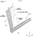
- FIG. 7 is a perspective view of an analysis model showing a deformation state of an L-shaped structure in a case where a load Px in an X-axis negative direction is applied.
- FIG. 8 is a cross-sectional view taken along line A-A shown in FIG. 7 to show a deformation state of a state in which a transversal member is cut along line A-A.
- FIG. 9 is an enlarged view of major parts in a cut portion shown in FIG. 8 .
- FIG. 10 is a diagram showing points on the displacement extraction surface before and after the deformation defined in a first step.
- FIG. 11A is a diagram for describing a method of setting vectors on an undeformed cross section in a second step to show the entire coordinate system.
- FIG. 11B is a diagram for describing the method of setting the vectors on the undeformed cross section in the second step to show a member coordinate system.
- FIG. 12A is a diagram for describing a method of setting vectors on a deformed cross section in the second step to show the entire coordinate system.
- FIG. 12B is a diagram for describing the method of setting the vectors on the deformed cross section in the second step to show a member coordinate system.
- FIG. 13 is a diagram for describing a method of calculating rotation angles in a third step.
- FIG. 14A is a diagram showing a method of setting vectors for calculating rotation angles of a triangular element.
- FIG. 14B is a diagram showing the method of setting the vectors for calculating the rotation angles of the triangular element.
- FIG. 14C is a diagram showing the method of setting the vectors for calculating the rotation angles of the triangular element.
- FIG. 14D is a diagram showing the method of setting the vectors for calculating the rotation angles of the triangular element.
- FIG. 15A is a diagram for describing a method of setting normal vectors of the triangular element to show the entire coordinate system.
- FIG. 15B is a diagram for describing the method of setting the normal vectors of the triangular element to show a member coordinate system.
- FIG. 16 is a diagram showing points on the displacement extraction surface before and after the deformation to describe a case where there are a coarse region and a dense region in arrangement of panel points on the cross section.
- FIG. 17 is a perspective view of an analysis model showing a deformation state of the L-shaped structure in a case where a load Py in a Y-axis positive direction is applied.
- FIG. 18 is a cross sectional view taken along line B-B shown in FIG. 17 to show a deformation state in which a longitudinal member is cut along line B-B.
- FIG. 19 is an enlarged view of major parts in a cut portion shown in FIG. 18 .
- FIG. 20 is a perspective view of an analysis model showing a deformation state of the L-shaped structure in a case where a torsional load Mz around a Z axis is applied.
- FIG. 21 is a cross sectional view taken along line C-C shown in FIG. 20 to show a deformation state in which the transversal member is cut along line C-C.
- FIG. 22 is an enlarged view of major parts in a cut portion shown in FIG. 21 .
- FIG. 23A is a diagram showing a result acquired by analyzing a deformation mode in a case where the load Px is applied to the structure to show displacements of the longitudinal member.
- FIG. 23B is a diagram showing a result acquired by analyzing the deformation mode in a case where the load Px is applied to the structure to show rotation angles of the longitudinal member.
- FIG. 24A is a diagram showing the result acquired by analyzing the deformation mode in a case where the load Px is applied to the structure to show displacements of the transversal member.
- FIG. 24B is a diagram showing the result acquired by analyzing the deformation mode in a case where the load Px is applied to the structure to show rotation angles of the transversal member.
- FIG. 25A is a diagram showing a result acquired by analyzing a deformation mode in a case where the load Py is applied to the structure to show displacements of the longitudinal member.
- FIG. 25B is a diagram showing a result acquired by analyzing the deformation mode in a case where the load Py is applied to the structure to show rotation angles of the longitudinal member.
- FIG. 26A is a diagram showing the result acquired by analyzing the deformation mode in a case where the load Py is applied to the structure to show displacements of the transversal member.
- FIG. 26B is a diagram showing the result acquired by analyzing the deformation mode in a case where the load Py is applied to the structure to show rotation angles of the transversal member.
- FIG. 27A is a diagram showing a result acquired by analyzing a deformation mode in a case where the torsional load Mz is applied to the structure to show displacements of the longitudinal member.
- FIG. 27B is a diagram showing a result acquired by analyzing the deformation mode in a case where the torsional load Mz is applied to the structure to show rotation angles of the longitudinal member.
- FIG. 28A is a diagram showing the result acquired by analyzing the deformation mode in a case where the torsional load Mz is applied to the structure to show displacements of the transversal member.
- FIG. 28B is a diagram showing the result acquired by analyzing the deformation mode in a case where the torsional load Mz is applied to the structure to show rotation angles of the transversal member.
- FIG. 29 is a diagram showing a result acquired by calculating a torsional angle of the transversal member around the X axis in the structure that influenced by the load Py in the Y-axis positive direction.
- FIG. 30 is a perspective view showing a configuration of a test object for a structural test according to a second embodiment of the present invention.
- FIG. 31 is a diagram for describing a photographic measurement method for the test object shown in FIG. 30 .
- FIG. 32 is a perspective view for describing a method of ascertaining the deformation mode of the structure of the related art.
- FIG. 33 is a diagram showing a result (deflection of the longitudinal member) acquired through the deformation measurement of FIG. 32 .
- FIG. 34 is a diagram showing a result (deflection of the transversal member) acquired through the deformation measurement of FIG. 32 .
- FIG. 35 is a perspective view showing a first structure according to a third embodiment of the present invention.
- FIG. 36A is a perspective view showing a loading state of the first structure of FIG. 35 .
- FIG. 36B is a perspective view showing a displacement extraction surface of a transversal member of the first structure of FIG. 35 .
- FIG. 36C is a perspective view showing a displacement extraction surface of a longitudinal member of the first structure of FIG. 35 .
- FIG. 37 is a diagram showing a deformation separation result as a result using the load Pz.
- FIG. 38 is a perspective view showing a second structure according to a modification example.
- FIG. 39 is a perspective view showing a third structure according to a modification example.
- FIG. 40 is a perspective view showing a fourth structure according to a modification example.
- a deformation mode analysis method of analyzing a deformation mode of an L-shaped structure 1 including a transversal member 11 (having a length of LX) having a hexagonal cross section and a longitudinal member 12 in a case where the structure 1 acquired by connecting the member 11 to the member 12 (having a length of LZ) having a rectangular cross section through a joint portion 13 is deformed due to a load will be described.
- a member axial direction of the transversal member 11 is an X axis
- a member axial direction of the longitudinal member 12 is a Z axis
- a direction in which the X axis and the Z axis are perpendicular to each other is a Y axis.
- a direction opposite to an approach of the joint portion 13 to the transversal member 11 on the X axis is a positive direction
- the approach of the joint portion 13 to the transversal member is a negative direction
- an approach to a depth direction of a paper surface of FIG. 2 on the Y axis is a positive direction
- an opposite direction thereto is a negative direction.
- the deformation mode analysis method of the structure in a case where a load Px in the X-axis negative direction, a load Py in the Y-axis positive direction, and a torsional load Mz around the Z axis are independently applied to a tip end surface 12 a of the longitudinal member 12 on the Z axis in a state in which an end surface (fixation end 11 a ) of the transversal member 11 in the X-axis positive direction is fixed will be described.
- the entire shape of the structure 1 as a target is not limited to the L shape, and a partial structure may be acquired by removing a part of the entire structure including a plurality of members.
- a boundary condition (support condition or load condition) in a case where such a partial structure is examined may be determined based on a movement of the partial structure in the entire structure.
- the deformation mode analysis method of the structure according to the present embodiment corresponds to a case where structural analysis of the flow of the deformation mode analysis method shown in FIG. 3 is performed, and evaluates deformation characteristics of the structure 1 including the transversal member 11 and the longitudinal member 12 .
- a specific deformation mode analysis method of the structure includes a process (first step S 1 ) of setting an outline of a cross section of an undeformed member cross section from the result of the structural analysis, setting an arbitrary first point in the outline and a second point which is different from the first point and is located on a displacement extraction surface including the member cross section, as a displacement extraction point, and extracting coordinates of the first point and the second point before and after the deformation of the member, a process (second step S 2 ) of calculating vectors using the first point and the second point before and after the deformation of the member, a process (third step S 3 ) of calculating displacements of the first point and the second point before and after the deformation and angles formed by the vectors before and after the deformation, a process (fourth step S 4 ) of calculating translational displacements and rotation angles as the member cross section from the displacements and the angles, a process (fifth step S 5 ) of calculating change amounts of the translational displacements and change amounts of the rotation angles as the member
- the structural analysis device 2 is a computer that performs the deformation mode analysis method of the structure 1 shown in FIG. 1 , and includes a storage unit 21 and a processing unit 22 .
- the storage unit 21 of the structural analysis device 2 stores a computer program capable of realizing the deformation mode analysis method of the structure 1 , other computer programs, or analysis data.
- a hard disk a magneto-optical disk, a flash memory, a random access memory (RAM), or a combination thereof may be used.
- a hard disk a magneto-optical disk, a flash memory, a random access memory (RAM), or a combination thereof may be used.
- a magneto-optical disk a magneto-optical disk
- a flash memory a flash memory
- RAM random access memory
- the processing unit 22 of the structural analysis device 2 includes a model creation unit 23 , a structural analysis unit 24 , and a mode analysis unit 25 .
- the model creation unit 23 creates an analysis model of the structure 1 offered for the structural analysis, and stores the generated analysis model in the storage unit 21 .
- a finite element method analysis model 10 (see FIG. 5 ) may be used.
- the structural analysis unit 24 performs the structural analysis using the finite element method analysis model 10 .
- the analysis method is not limited to such a finite element method analysis model 10 , and a boundary element method model or a finite difference method model may be used. In this case, a boundary element method or a finite difference method is used as an analysis method.
- the mode analysis unit 25 performs the respective procedures of steps S 1 to S 6 of FIG. 3 , analyzes the result of the structural analysis, and performs the analysis of the deformation mode of the structure 1 .
- An input and output device 3 that includes input means 31 and display means 32 is connected to the structural analysis device 2 .
- An input device such as a keyboard or a mouse may be used as the input means 31 .
- a printer device may also be used as the display means 32 .
- the analysis model 10 is created by outputting an instruction to the model creation unit 23 , and the structural analysis is performed by outputting an instruction to the structural analysis unit 24 .
- the mode analysis unit 25 may analyze the structural analysis, and may analyze the deformation mode of the member constituting the structure 1 .
- the analysis model 10 , data of the structural analysis result, or data of the deformation mode analysis may be recorded in the storage unit 21 , and data recorded in the storage unit 21 may be read through the processing unit 22 and may be output to the display means 32 .
- the computer program capable of realizing the deformation mode analysis method according to the present embodiment may realize the deformation mode analysis method by combining computer programs already stored in a computer system.
- the computer program may be recorded in a computer-readable storage medium, and may be read into and may be performed in the computer.
- the computer system includes an operating system (OS) or hardware such as a peripheral device.
- OS operating system
- hardware such as a peripheral device.
- the deformation mode of the structure 1 is analyzed based on the finite element method analysis model 10 shown in FIG. 5 in a deformation state in a case where any one of the loads Px, Py, and Mz shown in FIG. 2 is applied to the L-shaped structure 1 shown in FIG. 1 .
- XYZ shown in FIGS. 2, 5, and 7 to 12B represent the entire coordinate system.
- the load Px in the X-axis negative direction, the load Py in the Y-axis positive direction, and the torsional load Mz around the Z axis are independently applied to the end surface (tip end surface 12 a ) of the longitudinal member 12 in the Z-axis positive direction under the support condition in which the degrees of freedom of a panel point of the finite element method analysis model 10 of the structure 1 are fixed on the end surface (fixation end 11 a ) of the transversal member 11 in the X-axis positive direction.
- a panel point connected to the cross section of the member which is a rigid element is formed on the end surface (tip end surface 12 a ) of the longitudinal member 12 in the Z-axis positive direction, and this point is used as a loading point F that applies a load.
- coordinates of the displacement extraction point of the transversal member 11 on the cross section may be extracted as coordinates of intersection points of element boundary lines in the finite element analysis method model 10 with a displacement extraction surface D (plane including the member cross section) which is approximately perpendicular to the member axial direction of the transversal member 11 in the analysis model.
- a displacement extraction surface D plane including the member cross section
- the shape of the element may be another shape such as a triangle.
- FIG. 6 shows an example of a shell element, but may be a solid element.
- a displacement may be extracted based on coordinates of intersection points of element boundary lines on a surface such as a front surface, a rear surface, or an intermediate surface between the front and rear surfaces of a solid element with a displacement extraction surface.
- a distance between the extracted point and an adjacent point is short, a plurality of points may be aggregated as one point.
- FIG. 7 shows a deformation state of the L-shaped structure 1 in a case where the load Px in the negative direction of the X axis is applied at the loading point F of the longitudinal member 12 .
- bending deformation around the Y axis primarily occurs in the longitudinal member 12 and the transversal member 11 .
- an undeformed cross section iSA is changed to a deformed cross section dSA while accompanying the rotation of the cross section around the Y axis and the displacement of the cross section in a Z-axis direction.
- the undeformed cross section iSA is changed to the deformed cross section dSA while accompanying deformation in which the cross section extending in the Z-axis direction and contracting in a Y-axis direction is distorted.
- a centroid of the undeformed cross section iSA and a centroid of the deformed cross section dSA are respectively determined as a point O and a point O′, as points out of the outline within the displacement extraction surface D.
- These centroids O and O′ are equivalent to the second points (displacement extraction points) which are different from the first points and are located on the displacement extraction surface including the member cross section.
- the vectors using the first points and the second points are calculated before and after the deformation of the member.
- a displacement when the triangular element sEk is deformed to the triangular element sEk′ is calculated as an average value of displacements (point k->point k′, point k+1->point k+1′, point O->point O′) of coordinates of the respective vertices of the triangular element before and after the deformation.
- a rotation angle when the triangular element sEk is deformed to the triangular element sEk′ is calculated using the vectors calculated using the vertices (including the points (central points of the respective vertices) determined based on the respective vertices) of the triangular elements.
- a vector iAmk(k+1) acquired by connecting a central point mk(k+1) of a side k(k+1) of the undeformed triangular element and the centroid O is determined.
- a member coordinate system X0Y0Z0 is determined using the member axial direction (approximately a normal direction of the cross section) of the transversal member 11 as an X0 axis
- the vector iAmk(k+1) is provided such that an origin of the member coordinate system matches the centroid O
- vectors projected on a Y0Z0 surface, a Z0X0 surface, and an X0Y0 surface are used as a vector a, a vector b, and a vector c, as shown in FIG. 11B .
- a rotation angle of the vector a around the X0 axis is ⁇
- a rotation angle of the vector b around the Y0 axis is ⁇
- a rotation angle of the vector c around the Z0 axis is ⁇ .
- a vector dAmk(k+1) acquired by connecting a central point mk′(k+1)′ of a side k′(k+1)′ of the deformed triangular element and the centroid O′ is determined.
- vectors projected on the Y0Z0 surface, the Z0X0 surface, and the X0Y0 surface in the member coordinate system X0Y0Z0 are respectively a vector a′, a vector b′, and a vector c′.
- a rotation angle of the vector a′ around the X0 axis is ⁇ ′
- a rotation angle of the vector b′ around the Y0 axis is ⁇ ′
- a rotation angle of the vector c′ around the Z0 axis is ⁇ ′.
- a rotation angle ⁇ a is calculated based on an outer product a ⁇ a′ of the vector, as represented by the following expression (1).
- ⁇ a a sin [
- rotation angles when the triangular element sEk is deformed to the triangular element sEk′ are calculated as ( ⁇ a, ⁇ b, and ⁇ c).
- a method of calculating a vector acquired by connecting two points in the outline or a method (to be described below) of calculating a vector in a normal direction with respect to the member cross section may be used in addition to a method of calculating a vector acquired by connecting two points including one point in the outline and one point out of the outline within the plane including the member cross section.
- the rotation angle of the triangular element may be calculated based on the vector determined by a method other than the vector iAmk(k+1) within the surface shown in FIGS. 11A to 12B, and 14A .
- the rotation angle of the triangular element may be calculated as an average value of the rotation angles of the vectors iAOk and iAO(k+1) using the centroid O of the triangular element as an origin.
- the rotation angle of the triangular element may be calculated as the rotation angle of the vector iAk(k+1) acquired by connecting the point k and the point k+1.
- the displacement and the rotation angle as the cross section the triangular element may be calculated using only the points in the outline without setting the triangular element, that is, without using the centroid O out of the outline.
- the rotation angle of the triangular element may be calculated as an average of iAk(k+1), iAOk, and iAO(k+1).
- a normal vector N (a magnitude of a vector may be arbitrary and a unit vector may be determined) of the triangular element shown in FIGS. 15A and 15B may be used as described above irrespective of the vector within the surface of the triangular element as shown in FIGS. 11A to 14D .
- FIG. 17 shows the deformation state of the L-shaped structure 1 in a case where the load Py in the Y-axis positive direction is applied at the loading point F of the longitudinal member 12 .
- the bending deformation around the X axis is generated in the longitudinal member 12
- the bending deformation around the Z axis and the torsional deformation around the X axis are generated in the transversal member 11 .
- an undeformed cross section iSB is primarily changed to a deformed cross section dSB while accompanying the rotation of the cross section around the X axis and the displacement of the cross section to the Y-axis direction.
- the cross section of the undeformed cross section iSB is changed to the deformed cross section dSB while accompanying the deformation in which the cross section is distorted.
- FIG. 20 shows the deformation state of the L-shaped structure 1 in a case where the torsional load Mz around the Z axis is applied at the loading point F of the longitudinal member 12 .
- the torsional deformation around the Z axis is generated in the longitudinal member 12
- the bending deformation around the Z axis is generated in the transversal member 11 .
- an undeformed cross section iSC is primarily changed to a deformed cross section dSc while accompanying the displacement of the cross section to the Z-axis direction.
- the rotation angle ⁇ of the triangular element is calculated as an average value of the rotation angles of the vectors iAOk and iAO(k+1) using the centroid O of the triangular element as the origin, that is, the method shown in FIG. 14B by using the point out of the outline as the centroid O.
- a horizontal axis represents a location (mm) of the cross section in a lengthwise direction of the member (transversal member 11 or longitudinal member 12 ), and a vertical axis represents a displacement ⁇ (mm) or a rotation angle ⁇ (rad).
- the change amounts in the translational displacement and the rotation angle as the member cross section from the displacements and the rotation angles in the locations of two or more arbitrary cross sections in the lengthwise direction are calculated (fifth step S 5 ).
- Values (distances) of a location LX of the transversal member 11 and a location LZ of the longitudinal member 12 become larger as these locations become closer to the positive direction from the negative direction.
- a rotation angle ⁇ Y of the longitudinal member 12 around the Y axis, a rotation angle ⁇ Y of the transversal member 11 around the Y axis, and a rotation angle ⁇ Z thereof around the Z axis are generated and are changed in the lengthwise direction of the member.
- the rotation angle ⁇ X of the longitudinal member 12 around the X axis, the rotation angle ⁇ Z thereof around the Z axis, the rotation angle ⁇ X of the transversal member 11 around the X axis are rarely generated (sixth step S 6 ).
- the deformation mode analysis method for the member of the structure is performed, and thus, the place and the deformation state in which the displacement or the rotation angle is in progress may be quantitatively recognized based on three-dimensional deformation amounts ( ⁇ X, ⁇ Y, ⁇ Z, ⁇ X, ⁇ Y, and ⁇ Z) in the member constituting the structure.
- a portion and a deformation state acting as weakness in ensuring rigidity of the structure are recognized based on the analysis result of the deformation modes, and thus, it is possible to efficiently find a structure specification for ensuring the rigidity.
- FIG. 29 shows a result acquired by calculating a torsional angle ⁇ x of the transversal member 11 around the X axis in the L-shaped structure 1 (see FIG. 17 ) that is influenced by the load Py in the Y-axis positive direction.
- FIGS. 14A, 14B, and 14D using the point in the outline of the member cross section and the point out of the outline within the displacement extraction surface D are used, it can be seen that an error is generated in an evaluation value and there is a tendency for the result and evaluation value to be separated from the results and evaluation values of the other methods in a case where the method of FIG. 14C without using the point out of the outline is used.
- the deformation mode analysis method for the structure the structure reinforcement method using the deformation mode analysis method, the computer program for the deformation mode analysis of the structure, and the recording medium according to the present embodiment described above, it is possible to analyze a complicated deformation in which the bending or torsion generated in the member constituting the structure is coupled, and it is possible to provide an effective reinforcement method depending on the deformation mode.
- a deformation mode analysis method for a structure according to a second embodiment is applied to a structural test.
- the structural test is performed using only the mode analysis unit 25 without using the model creation unit 23 and the structural analysis unit 24 of the processing unit 22 of the structural analysis device 2 shown in FIG. 4 in the deformation mode analysis flow shown in FIG. 3 .
- the deformation mode of the structure is analyzed based on a structural test using a test object 1 A (structure).
- XYZ represent the entire coordinate system.
- the test object 1 A has the same shape as the L-shaped structure 1 shown in FIG. 1 including the transversal member 11 and the longitudinal member 12 , fixes and supports an end surface 11 a of the transversal member 11 in the X-axis positive direction by clamping the end surface to a plate-shaped fixture 14 , and provides a loading plate 15 on an end surface 12 a of the longitudinal member 12 in the Z-axis positive direction.
- the structural test is performed by applying a load (load Px in the negative direction of the X axis shown in FIG. 30 ) to such a test object 1 A in a loading device 16 connected to the loading plate 15 .
- coordinates at the outline on the member cross section of the transversal member 11 are measured by photographic measurement (photographic measurement for a space coordinate of a measurement point or a dimension and a shape of the object by analyzing disparity information from a two-dimensional image acquired by capturing a three-dimensional object from a plurality of observation points) using the principle of photogrammetry. Coordinates in the outline on the member cross section of the longitudinal member 12 may also be measured by the same method.
- a point on the substantially same cross section is determined as a displacement measurement point on a plurality of cross sections of the transversal member 11 .
- a measurement target 41 for photographic measurement using a material having a high to light is provided at the displacement measurement point, and flash photographing is performed in a camera 40 for photographic measurement.
- the positional relationship is established between the measurement target 41 and the code target A by providing the code target 42 in a member as a measuring target or a measurement jig (not shown) near the member and applying the code target in a measurement photograph simultaneously with the measurement target 41 .
- it is possible to improve measurement precision by providing a standard point and a standard scale near the measuring target and using the standard point and the standard scale as a reference point and a standard of a reference length in a measurement space.
- the coordinates of the point of the member of the test object 1 A before a load is applied to the loading plate 15 is measured in the camera 40 for photographic measurement (photographic measurement is performed), and subsequently, the coordinates of the point (corresponding to a deformed point of an arbitrary undeformed point) of the member of the test object 1 A in a state in which the load is applied to the loading plate 15 by the loading device 16 and the loading plate is held, that is, after the deformation is performed, are measured.
- a difference between the measurement coordinates before and after the deformation is performed, and thus, it is possible to extract a three-dimensional displacement of coordinates of a point in the measurement space.
- the displacements of the member of the test object 1 A are evaluated through the photographic measurement, and thus, it is possible to easily extract the displacements and the rotation angles as the member cross section having a complicated cross-section shape. Accordingly, it is possible to quantitatively evaluate the deformation mode of the structure in only a testing stage or a previously developed stage.
- a method of separating the structure into regions of the respective members and areas of connections for the respective members, calculating a contribution of the deformation for each separated region through analysis, and analyzing the deformation mode of the structure is used.
- a specific example will be described.
- the third embodiment is an example of a method of analyzing a displacement of a first structure 5 A (see FIG. 35 ) as an evaluating target, which is generated due to a load, by quantitatively evaluating a degree of influence due to the deformation of each member constituting the first structure 5 A.
- the first structure 5 A is a part of the entire structure such as a vehicle (for example, a car) and is formed in a T shape acquired by coupling a longitudinal member 52 to a central portion of a transversal member 51 in a member axial direction.
- the longitudinal member 52 is configured such that a flange 52 a protrudes in a direction perpendicular to the member axial direction at a connection end with the transversal member 51 is connected to a side surface 51 a of the transversal member 51 .
- a reference symbol Hc shown in FIG. 35 denotes a height dimension of the longitudinal member 52
- a reference symbol Hs denotes a height dimension of the transversal member 51 .
- a direction in parallel with the member axial direction of the transversal member 51 is referred to as an X1 direction
- a direction in parallel with the member axial direction of the longitudinal member 52 is referred to as a Y1 direction
- a direction perpendicular to a plane including the X1 direction and the Y1 direction is referred to as a Z1 direction.
- a contribution of the deformation in a case where end surfaces 51 e and 51 f of the transversal member 51 of the first structure 5 A are fixed and a load Pz is applied to a central point F 1 of an end surface 52 e of the longitudinal member 52 of the first structure 5 A is analyzed.
- a region of a connection 53 of the transversal member 51 and the longitudinal member 52 of the first structure 5 A is determined as a region surrounded by displacement extraction surfaces D 1 a , D 1 b , and D 1 c shown in FIGS. 36B and 36C .
- a region of the longitudinal member 52 is determined as a region between the displacement extraction surface D 1 c and the end surface 52 e
- a region of the transversal member 51 is determined as a region between the displacement extraction surface D 1 a and the end surface 51 e and a region between the displacement extraction surface D 1 b and the end surface 51 f.
- a displacement in this case is the sum of displacements of the central point F 1 due to the deformations of the regions of the transversal member 51 , the longitudinal member 52 , and the connection 53 .
- a displacement of the central point F 1 generated due to the deformation of the transversal member 51 is US
- a displacement of the central point F 1 generated due to the deformation of the longitudinal member 52 is UC
- a displacement of the central point F 1 generated due to the deformation of the connection 53 is UL
- the displacements UC, US, and UL may be calculated based on the displacement of the loading point (central point F 1 ), the translational displacements and the rotation angles of the displacement extraction surfaces D 1 a , D 1 b , and D 1 c , and the dimensions of the respective regions.
- FIG. 37 shows the displacement (displacement) of the loading point (central point F 1 ) when the load Pz is applied in three cases where a height Hs of the transversal member 51 is 125 mm and a height Hc of the longitudinal member 52 is sequentially changed to 75 mm, 100 mm, and 125 mm. It can be checked through this result that a contribution of a local deformation UL of the connection 53 is large in the deformation of the first structure 5 A. It can be seen that as the height Hc of the longitudinal member 52 becomes closer to the height Hs of the transversal member 51 , the generation of the local deformation UL of the connection 53 is suppressed, and thus, the rigidity of the structure is improved.
- the structure is not limited to the structure having such a shape.
- the structure has a shape such as an L-shaped second structure 5 B as shown in FIG. 38 , a T-shaped third structure 5 C of which the transversal member 51 is curved as shown in FIG. 39 , or a cruciform-joint-shaped fourth structure 5 D shown in FIG. 40 , it is possible to analyze the structure by setting the separated regions.
- the structure into the transversal member 51 , a first joint 54 , a second joint 55 , a connection 56 of the transversal member 51 with the first joint 54 , and a connection 57 of the transversal member 51 with the second joint 55 , as the separated regions in the case of the fourth structure D shown in FIG. 40 .
- the present invention is not limited to only the respective embodiments, and may be appropriately changed without departing from the gist thereof.
- the deformation mode analysis of the structure 1 (test object 1 A) constituted by the member of which the member axis is a straight line and the cross section is a closed cross section has been described in the first embodiment and the second embodiment, it is possible to similarly perform deformation mode analysis on a structure constituted by the member having a curved member axis or an opened cross section.
- the deformation mode analysis method for the structure the structure reinforcement method using the deformation mode analysis method, the computer program for the deformation mode analysis of the structure, and the recording medium of the present invention, it is possible to analyze a complicated deformation in which the bending or torsion generated in the member constituting the structure is coupled, and it is possible to provide an effective reinforcement method depending on the deformation mode.
Landscapes
- Engineering & Computer Science (AREA)
- Physics & Mathematics (AREA)
- General Physics & Mathematics (AREA)
- Theoretical Computer Science (AREA)
- Aviation & Aerospace Engineering (AREA)
- General Engineering & Computer Science (AREA)
- Computer Hardware Design (AREA)
- Evolutionary Computation (AREA)
- Geometry (AREA)
- Electromagnetism (AREA)
- Investigating Strength Of Materials By Application Of Mechanical Stress (AREA)
- Architecture (AREA)
- Software Systems (AREA)
- Human Computer Interaction (AREA)
- Health & Medical Sciences (AREA)
- Life Sciences & Earth Sciences (AREA)
- Chemical & Material Sciences (AREA)
- Analytical Chemistry (AREA)
- Biochemistry (AREA)
- General Health & Medical Sciences (AREA)
- Immunology (AREA)
- Pathology (AREA)
Abstract
Description
[Expression 1]
θa=a sin [|a×a′|/(|a||a′|)] (1)
[Expression 2]
θb=a sin [|b×b′|/(|b||b′|)] (2)
[Expression 3]
θc=a sin [|c×c′|/(|c||c′|)] (3)
-
- 1, 5A, 5B, 5C: STRUCTURE
- 1A: TEST OBJECT
- 2: STRUCTURAL ANALYSIS DEVICE
- 3: INPUT AND OUTPUT DEVICE
- 10: FINITE ELEMENT METHOD ANALYSIS MODEL
- 11: TRANSVERSAL MEMBER
- 11 a: FIXATION END
- 12: LONGITUDINAL MEMBER
- 12 a: TIP END SURFACE
- 40: CAMERA FOR PHOTOGRAPHIC MEASUREMENT
- 41: MEASUREMENT TARGET
- 42: CODE TARGET
- F: LOADING POINT
Claims (23)
Applications Claiming Priority (3)
| Application Number | Priority Date | Filing Date | Title |
|---|---|---|---|
| JP2014190141 | 2014-09-18 | ||
| JP2014-190141 | 2014-09-18 | ||
| PCT/JP2015/076448 WO2016043261A1 (en) | 2014-09-18 | 2015-09-17 | Deformation mode analysis method for member of structure, structure reinforcement method using deformation mode analysis method, computer program for deformation mode analysis of structure, and recording medium |
Publications (2)
| Publication Number | Publication Date |
|---|---|
| US20170293366A1 US20170293366A1 (en) | 2017-10-12 |
| US10598565B2 true US10598565B2 (en) | 2020-03-24 |
Family
ID=55533297
Family Applications (1)
| Application Number | Title | Priority Date | Filing Date |
|---|---|---|---|
| US15/511,828 Active 2036-03-22 US10598565B2 (en) | 2014-09-18 | 2015-09-17 | Deformation mode analysis method for member of structure, structure reinforcement method using deformation mode analysis method, computer program for deformation mode analysis of structure, and recording medium |
Country Status (5)
| Country | Link |
|---|---|
| US (1) | US10598565B2 (en) |
| JP (1) | JP6319451B2 (en) |
| KR (1) | KR101932867B1 (en) |
| CN (1) | CN107077518B (en) |
| WO (1) | WO2016043261A1 (en) |
Cited By (1)
| Publication number | Priority date | Publication date | Assignee | Title |
|---|---|---|---|---|
| US20200349302A1 (en) * | 2019-05-03 | 2020-11-05 | Honda Research Institute Europe Gmbh | Method for structural optimization of objects using a descriptor for deformation modes |
Families Citing this family (11)
| Publication number | Priority date | Publication date | Assignee | Title |
|---|---|---|---|---|
| WO2017077609A1 (en) * | 2015-11-04 | 2017-05-11 | 富士通株式会社 | Structural analysis method and structural analysis program |
| KR101910871B1 (en) * | 2017-08-31 | 2018-12-31 | 주식회사 화승알앤에이 | Method for interpreting a layout of a tube using three-dimensional coordinates and recording medium thereof |
| CN111177853A (en) * | 2019-12-31 | 2020-05-19 | 中国航空工业集团公司沈阳飞机设计研究所 | Wing type framework design method |
| CN111307614B (en) * | 2020-03-31 | 2022-06-10 | 广西交科集团有限公司 | Method for determination of segmental flexural and shear stiffness of continuous beams |
| CN111488661B (en) * | 2020-04-14 | 2022-05-03 | 清华大学 | Cylindrical gear contact analysis method considering line external meshing |
| CN111323297A (en) * | 2020-04-15 | 2020-06-23 | 西北核技术研究院 | Three-dimensional deformation and abrasion measurement method of projectile |
| CN112613211B (en) * | 2020-12-22 | 2022-10-21 | 郑州大学 | Deformation decomposition method for any triangular unit in planar structure |
| JP7690783B2 (en) * | 2021-06-07 | 2025-06-11 | 住友ゴム工業株式会社 | Airless tire simulation method |
| CN113640146A (en) * | 2021-07-21 | 2021-11-12 | 东风柳州汽车有限公司 | Vehicle canopy torsion resistance evaluation method, device, equipment and storage medium |
| CN114186310B (en) * | 2021-11-23 | 2024-09-06 | 郑州大学 | Structural deformation decomposition method based on spatial 8-node wall element |
| CN116562108B (en) * | 2023-07-10 | 2023-10-03 | 通用技术集团机床工程研究院有限公司 | Z-direction deformation calculation and compensation method for abutting surface of beam guide rail |
Citations (13)
| Publication number | Priority date | Publication date | Assignee | Title |
|---|---|---|---|---|
| JPH02159531A (en) | 1988-12-13 | 1990-06-19 | Mitsubishi Heavy Ind Ltd | Measurement of change in deflection shape for construction |
| CN1414194A (en) | 2002-11-21 | 2003-04-30 | 西安理工大学 | Pull, press, bend coupling boundary element meathod of beam containing mang flexible joining parts |
| US6704693B1 (en) * | 1999-10-15 | 2004-03-09 | Moldflow Pty Ltd | Apparatus and method for structural analysis |
| US6876956B1 (en) * | 1999-08-31 | 2005-04-05 | California Institute Of Technology | Method and system for thin-shell finite-element analysis |
| US6901809B2 (en) * | 2000-11-17 | 2005-06-07 | Battelle Memorial Institute | Structural stress analysis |
| JP2006119005A (en) | 2004-10-22 | 2006-05-11 | Ryonichi Engineering Co Ltd | Large-scale structure measuring device and large-scale structure measuring method |
| JP2008015635A (en) | 2006-07-03 | 2008-01-24 | Toyota Central Res & Dev Lab Inc | Structure evaluation method and program thereof |
| CN101750017A (en) | 2010-01-18 | 2010-06-23 | 战强 | Visual detection method of multi-movement target positions in large view field |
| JP2011164031A (en) | 2010-02-12 | 2011-08-25 | Yokohama Rubber Co Ltd:The | Method and computer program for determining vibration mode of ring-shaped structure |
| JP2013037437A (en) | 2011-08-04 | 2013-02-21 | Fujitsu Ltd | Structural analysis system, structural analysis program and structural analysis method |
| JP2013050814A (en) | 2011-08-30 | 2013-03-14 | Toyota Motor Corp | Analysis method of rigid body motion and elastic deformation |
| CN103630105A (en) * | 2013-11-27 | 2014-03-12 | 中国航空工业集团公司沈阳发动机设计研究所 | Method for measuring deforming angle and centroid displacement of special-shaped structural component |
| US9026406B2 (en) * | 2011-05-24 | 2015-05-05 | Airbus Operations Limited | Method, apparatus and computer program product for determining the strain induced at a selected point in a stiffened panel structure in response to a load, taking into account one or more out of plane (OOP) effects |
-
2015
- 2015-09-17 JP JP2016548935A patent/JP6319451B2/en active Active
- 2015-09-17 US US15/511,828 patent/US10598565B2/en active Active
- 2015-09-17 KR KR1020177009120A patent/KR101932867B1/en active Active
- 2015-09-17 CN CN201580049905.0A patent/CN107077518B/en active Active
- 2015-09-17 WO PCT/JP2015/076448 patent/WO2016043261A1/en not_active Ceased
Patent Citations (13)
| Publication number | Priority date | Publication date | Assignee | Title |
|---|---|---|---|---|
| JPH02159531A (en) | 1988-12-13 | 1990-06-19 | Mitsubishi Heavy Ind Ltd | Measurement of change in deflection shape for construction |
| US6876956B1 (en) * | 1999-08-31 | 2005-04-05 | California Institute Of Technology | Method and system for thin-shell finite-element analysis |
| US6704693B1 (en) * | 1999-10-15 | 2004-03-09 | Moldflow Pty Ltd | Apparatus and method for structural analysis |
| US6901809B2 (en) * | 2000-11-17 | 2005-06-07 | Battelle Memorial Institute | Structural stress analysis |
| CN1414194A (en) | 2002-11-21 | 2003-04-30 | 西安理工大学 | Pull, press, bend coupling boundary element meathod of beam containing mang flexible joining parts |
| JP2006119005A (en) | 2004-10-22 | 2006-05-11 | Ryonichi Engineering Co Ltd | Large-scale structure measuring device and large-scale structure measuring method |
| JP2008015635A (en) | 2006-07-03 | 2008-01-24 | Toyota Central Res & Dev Lab Inc | Structure evaluation method and program thereof |
| CN101750017A (en) | 2010-01-18 | 2010-06-23 | 战强 | Visual detection method of multi-movement target positions in large view field |
| JP2011164031A (en) | 2010-02-12 | 2011-08-25 | Yokohama Rubber Co Ltd:The | Method and computer program for determining vibration mode of ring-shaped structure |
| US9026406B2 (en) * | 2011-05-24 | 2015-05-05 | Airbus Operations Limited | Method, apparatus and computer program product for determining the strain induced at a selected point in a stiffened panel structure in response to a load, taking into account one or more out of plane (OOP) effects |
| JP2013037437A (en) | 2011-08-04 | 2013-02-21 | Fujitsu Ltd | Structural analysis system, structural analysis program and structural analysis method |
| JP2013050814A (en) | 2011-08-30 | 2013-03-14 | Toyota Motor Corp | Analysis method of rigid body motion and elastic deformation |
| CN103630105A (en) * | 2013-11-27 | 2014-03-12 | 中国航空工业集团公司沈阳发动机设计研究所 | Method for measuring deforming angle and centroid displacement of special-shaped structural component |
Non-Patent Citations (5)
| Title |
|---|
| Chinese Office Action and Search Report for counterpart Chinese Application No. 201580049905.0, dated Oct. 21, 2019, with partial English translation. |
| Gotluru, B.P., et al. "Torsion in Thin-Walled Cold-Formed Steel Beams" Thin-Walled Structures, vol. 37, pp. 127-145 (2000) (Year: 2000). * |
| International Search Report for PCT/JP2015/076448 dated Nov. 24, 2015. |
| Robinson, J. "Structural Testing and Analysis of a Joined Wing Technology Demonstrator" Air Force Research Laboratory (2004) (Year: 2004). * |
| Written Opinion of the International Searching Authority for PCT/JP2015/076448 (PCT/ISA/237) dated Nov. 24, 2015. |
Cited By (1)
| Publication number | Priority date | Publication date | Assignee | Title |
|---|---|---|---|---|
| US20200349302A1 (en) * | 2019-05-03 | 2020-11-05 | Honda Research Institute Europe Gmbh | Method for structural optimization of objects using a descriptor for deformation modes |
Also Published As
| Publication number | Publication date |
|---|---|
| CN107077518B (en) | 2020-10-20 |
| KR101932867B1 (en) | 2018-12-27 |
| CN107077518A (en) | 2017-08-18 |
| JPWO2016043261A1 (en) | 2017-06-29 |
| US20170293366A1 (en) | 2017-10-12 |
| KR20170047391A (en) | 2017-05-04 |
| JP6319451B2 (en) | 2018-05-09 |
| WO2016043261A1 (en) | 2016-03-24 |
Similar Documents
| Publication | Publication Date | Title |
|---|---|---|
| US10598565B2 (en) | Deformation mode analysis method for member of structure, structure reinforcement method using deformation mode analysis method, computer program for deformation mode analysis of structure, and recording medium | |
| KR101011844B1 (en) | Fatigue Life Prediction Method for Spot Welded Structures | |
| Wang et al. | Identification of material parameters of PVC foams using digital image correlation and the virtual fields method | |
| JP6954368B2 (en) | Displacement component detection device, displacement component detection method, and program | |
| Mancini et al. | Stress magnification factor for angular misalignment between plates with welding-induced curvature | |
| JP6789452B1 (en) | Crack estimation device, crack estimation method, crack inspection method and failure diagnosis method | |
| Lai et al. | Framework for long-term structural health monitoring by computer vision and vibration-based model updating | |
| Du et al. | Evaluation using digital image correlation of stress intensity factors in an aerospace panel | |
| Hyldahl et al. | Behavior of thin rectangular ANCF shell elements in various mesh configurations | |
| US20190178814A1 (en) | State assessing device, state assessing method, and storage medium for storing program | |
| Jang et al. | Analysis of three thin-walled box beams connected at a joint under out-of-plane bending loads | |
| JP2004303227A (en) | Element distortion-analysis error relationship estimation method, analysis error estimation method, numerical analysis method, and computer program for implementing the methods | |
| JP7121650B2 (en) | Load calculator and aircraft | |
| Doukas et al. | On an empirical investigation of the structural behavior of robots | |
| JP4851252B2 (en) | Structure evaluation program | |
| JP6576125B2 (en) | Simulation method and simulation apparatus | |
| Wildy et al. | An algorithm for identifying a crack within a measured displacement field | |
| Kammer et al. | Formulation of an experimental substructure model using a Craig–Bampton based transmission simulator | |
| Gevinski et al. | Prediction of dynamic strain using modal parameters | |
| CN112632691B (en) | Virtual product assessment by adjusting the orientation of virtual component models | |
| US20150120232A1 (en) | Shape calculation apparatus and method, measurement apparatus, method of manufacturing article, storage medium | |
| Marinkovic et al. | Modal-space based solutions including geometric nonlinearities for flexible multi-body systems | |
| McGowan et al. | Full-field structural response of composite structures: analysis and experiment | |
| Iliopoulos et al. | On the feasibility of crack propagation tracking and full field strain imaging via a strain compatibility functional and the Direct Strain Imaging method | |
| Zenz et al. | Identification of system properties in a square frame undergoing large deformations: Numerical and experimental investigations |
Legal Events
| Date | Code | Title | Description |
|---|---|---|---|
| AS | Assignment |
Owner name: NIPPON STEEL & SUMITOMO METAL CORPORATION, JAPAN Free format text: ASSIGNMENT OF ASSIGNORS INTEREST;ASSIGNORS:SHIMIZU, NOBUTAKA;KAWACHI, TAKESHI;REEL/FRAME:041621/0596 Effective date: 20170303 |
|
| STPP | Information on status: patent application and granting procedure in general |
Free format text: RESPONSE TO NON-FINAL OFFICE ACTION ENTERED AND FORWARDED TO EXAMINER |
|
| AS | Assignment |
Owner name: NIPPON STEEL CORPORATION, JAPAN Free format text: CHANGE OF NAME;ASSIGNOR:NIPPON STEEL & SUMITOMO METAL CORPORATION;REEL/FRAME:049257/0828 Effective date: 20190401 |
|
| STPP | Information on status: patent application and granting procedure in general |
Free format text: NON FINAL ACTION MAILED |
|
| STPP | Information on status: patent application and granting procedure in general |
Free format text: RESPONSE TO NON-FINAL OFFICE ACTION ENTERED AND FORWARDED TO EXAMINER |
|
| STPP | Information on status: patent application and granting procedure in general |
Free format text: NOTICE OF ALLOWANCE MAILED -- APPLICATION RECEIVED IN OFFICE OF PUBLICATIONS |
|
| STPP | Information on status: patent application and granting procedure in general |
Free format text: NOTICE OF ALLOWANCE MAILED -- APPLICATION RECEIVED IN OFFICE OF PUBLICATIONS |
|
| STPP | Information on status: patent application and granting procedure in general |
Free format text: PUBLICATIONS -- ISSUE FEE PAYMENT VERIFIED |
|
| STCF | Information on status: patent grant |
Free format text: PATENTED CASE |
|
| MAFP | Maintenance fee payment |
Free format text: PAYMENT OF MAINTENANCE FEE, 4TH YEAR, LARGE ENTITY (ORIGINAL EVENT CODE: M1551); ENTITY STATUS OF PATENT OWNER: LARGE ENTITY Year of fee payment: 4 |