US10597336B2 - Porous ceramic structure - Google Patents
Porous ceramic structure Download PDFInfo
- Publication number
- US10597336B2 US10597336B2 US15/869,554 US201815869554A US10597336B2 US 10597336 B2 US10597336 B2 US 10597336B2 US 201815869554 A US201815869554 A US 201815869554A US 10597336 B2 US10597336 B2 US 10597336B2
- Authority
- US
- United States
- Prior art keywords
- porous ceramic
- ceramic structure
- adhesive
- bulk body
- principal surface
- Prior art date
- Legal status (The legal status is an assumption and is not a legal conclusion. Google has not performed a legal analysis and makes no representation as to the accuracy of the status listed.)
- Active
Links
Images


Classifications
-
- C—CHEMISTRY; METALLURGY
- C04—CEMENTS; CONCRETE; ARTIFICIAL STONE; CERAMICS; REFRACTORIES
- C04B—LIME, MAGNESIA; SLAG; CEMENTS; COMPOSITIONS THEREOF, e.g. MORTARS, CONCRETE OR LIKE BUILDING MATERIALS; ARTIFICIAL STONE; CERAMICS; REFRACTORIES; TREATMENT OF NATURAL STONE
- C04B38/00—Porous mortars, concrete, artificial stone or ceramic ware; Preparation thereof
- C04B38/007—Porous mortars, concrete, artificial stone or ceramic ware; Preparation thereof characterised by the pore distribution, e.g. inhomogeneous distribution of pores
- C04B38/0074—Porous mortars, concrete, artificial stone or ceramic ware; Preparation thereof characterised by the pore distribution, e.g. inhomogeneous distribution of pores expressed as porosity percentage
-
- B—PERFORMING OPERATIONS; TRANSPORTING
- B28—WORKING CEMENT, CLAY, OR STONE
- B28B—SHAPING CLAY OR OTHER CERAMIC COMPOSITIONS; SHAPING SLAG; SHAPING MIXTURES CONTAINING CEMENTITIOUS MATERIAL, e.g. PLASTER
- B28B11/00—Apparatus or processes for treating or working the shaped or preshaped articles
- B28B11/14—Apparatus or processes for treating or working the shaped or preshaped articles for dividing shaped articles by cutting
- B28B11/145—Apparatus or processes for treating or working the shaped or preshaped articles for dividing shaped articles by cutting for dividing block-shaped bodies of expanded materials, e.g. cellular concrete
-
- C—CHEMISTRY; METALLURGY
- C04—CEMENTS; CONCRETE; ARTIFICIAL STONE; CERAMICS; REFRACTORIES
- C04B—LIME, MAGNESIA; SLAG; CEMENTS; COMPOSITIONS THEREOF, e.g. MORTARS, CONCRETE OR LIKE BUILDING MATERIALS; ARTIFICIAL STONE; CERAMICS; REFRACTORIES; TREATMENT OF NATURAL STONE
- C04B35/00—Shaped ceramic products characterised by their composition; Ceramics compositions; Processing powders of inorganic compounds preparatory to the manufacturing of ceramic products
- C04B35/01—Shaped ceramic products characterised by their composition; Ceramics compositions; Processing powders of inorganic compounds preparatory to the manufacturing of ceramic products based on oxide ceramics
- C04B35/48—Shaped ceramic products characterised by their composition; Ceramics compositions; Processing powders of inorganic compounds preparatory to the manufacturing of ceramic products based on oxide ceramics based on zirconium or hafnium oxides, zirconates, zircon or hafnates
- C04B35/486—Fine ceramics
-
- C—CHEMISTRY; METALLURGY
- C04—CEMENTS; CONCRETE; ARTIFICIAL STONE; CERAMICS; REFRACTORIES
- C04B—LIME, MAGNESIA; SLAG; CEMENTS; COMPOSITIONS THEREOF, e.g. MORTARS, CONCRETE OR LIKE BUILDING MATERIALS; ARTIFICIAL STONE; CERAMICS; REFRACTORIES; TREATMENT OF NATURAL STONE
- C04B35/00—Shaped ceramic products characterised by their composition; Ceramics compositions; Processing powders of inorganic compounds preparatory to the manufacturing of ceramic products
- C04B35/622—Forming processes; Processing powders of inorganic compounds preparatory to the manufacturing of ceramic products
- C04B35/626—Preparing or treating the powders individually or as batches ; preparing or treating macroscopic reinforcing agents for ceramic products, e.g. fibres; mechanical aspects section B
- C04B35/62605—Treating the starting powders individually or as mixtures
- C04B35/6261—Milling
-
- C—CHEMISTRY; METALLURGY
- C04—CEMENTS; CONCRETE; ARTIFICIAL STONE; CERAMICS; REFRACTORIES
- C04B—LIME, MAGNESIA; SLAG; CEMENTS; COMPOSITIONS THEREOF, e.g. MORTARS, CONCRETE OR LIKE BUILDING MATERIALS; ARTIFICIAL STONE; CERAMICS; REFRACTORIES; TREATMENT OF NATURAL STONE
- C04B35/00—Shaped ceramic products characterised by their composition; Ceramics compositions; Processing powders of inorganic compounds preparatory to the manufacturing of ceramic products
- C04B35/622—Forming processes; Processing powders of inorganic compounds preparatory to the manufacturing of ceramic products
- C04B35/626—Preparing or treating the powders individually or as batches ; preparing or treating macroscopic reinforcing agents for ceramic products, e.g. fibres; mechanical aspects section B
- C04B35/63—Preparing or treating the powders individually or as batches ; preparing or treating macroscopic reinforcing agents for ceramic products, e.g. fibres; mechanical aspects section B using additives specially adapted for forming the products, e.g.. binder binders
- C04B35/632—Organic additives
- C04B35/634—Polymers
- C04B35/63404—Polymers obtained by reactions only involving carbon-to-carbon unsaturated bonds
- C04B35/6342—Polyvinylacetals, e.g. polyvinylbutyral [PVB]
-
- C—CHEMISTRY; METALLURGY
- C04—CEMENTS; CONCRETE; ARTIFICIAL STONE; CERAMICS; REFRACTORIES
- C04B—LIME, MAGNESIA; SLAG; CEMENTS; COMPOSITIONS THEREOF, e.g. MORTARS, CONCRETE OR LIKE BUILDING MATERIALS; ARTIFICIAL STONE; CERAMICS; REFRACTORIES; TREATMENT OF NATURAL STONE
- C04B38/00—Porous mortars, concrete, artificial stone or ceramic ware; Preparation thereof
- C04B38/0051—Porous mortars, concrete, artificial stone or ceramic ware; Preparation thereof characterised by the pore size, pore shape or kind of porosity
- C04B38/0054—Porous mortars, concrete, artificial stone or ceramic ware; Preparation thereof characterised by the pore size, pore shape or kind of porosity the pores being microsized or nanosized
-
- C—CHEMISTRY; METALLURGY
- C04—CEMENTS; CONCRETE; ARTIFICIAL STONE; CERAMICS; REFRACTORIES
- C04B—LIME, MAGNESIA; SLAG; CEMENTS; COMPOSITIONS THEREOF, e.g. MORTARS, CONCRETE OR LIKE BUILDING MATERIALS; ARTIFICIAL STONE; CERAMICS; REFRACTORIES; TREATMENT OF NATURAL STONE
- C04B38/00—Porous mortars, concrete, artificial stone or ceramic ware; Preparation thereof
- C04B38/009—Porous or hollow ceramic granular materials, e.g. microballoons
-
- C—CHEMISTRY; METALLURGY
- C04—CEMENTS; CONCRETE; ARTIFICIAL STONE; CERAMICS; REFRACTORIES
- C04B—LIME, MAGNESIA; SLAG; CEMENTS; COMPOSITIONS THEREOF, e.g. MORTARS, CONCRETE OR LIKE BUILDING MATERIALS; ARTIFICIAL STONE; CERAMICS; REFRACTORIES; TREATMENT OF NATURAL STONE
- C04B38/00—Porous mortars, concrete, artificial stone or ceramic ware; Preparation thereof
- C04B38/06—Porous mortars, concrete, artificial stone or ceramic ware; Preparation thereof by burning-out added substances by burning natural expanding materials or by sublimating or melting out added substances
- C04B38/063—Preparing or treating the raw materials individually or as batches
- C04B38/0635—Compounding ingredients
- C04B38/0645—Burnable, meltable, sublimable materials
- C04B38/067—Macromolecular compounds
-
- C—CHEMISTRY; METALLURGY
- C04—CEMENTS; CONCRETE; ARTIFICIAL STONE; CERAMICS; REFRACTORIES
- C04B—LIME, MAGNESIA; SLAG; CEMENTS; COMPOSITIONS THEREOF, e.g. MORTARS, CONCRETE OR LIKE BUILDING MATERIALS; ARTIFICIAL STONE; CERAMICS; REFRACTORIES; TREATMENT OF NATURAL STONE
- C04B38/00—Porous mortars, concrete, artificial stone or ceramic ware; Preparation thereof
- C04B38/08—Porous mortars, concrete, artificial stone or ceramic ware; Preparation thereof by adding porous substances
- C04B38/085—Porous mortars, concrete, artificial stone or ceramic ware; Preparation thereof by adding porous substances of micro- or nanosize
-
- C—CHEMISTRY; METALLURGY
- C04—CEMENTS; CONCRETE; ARTIFICIAL STONE; CERAMICS; REFRACTORIES
- C04B—LIME, MAGNESIA; SLAG; CEMENTS; COMPOSITIONS THEREOF, e.g. MORTARS, CONCRETE OR LIKE BUILDING MATERIALS; ARTIFICIAL STONE; CERAMICS; REFRACTORIES; TREATMENT OF NATURAL STONE
- C04B41/00—After-treatment of mortars, concrete, artificial stone or ceramics; Treatment of natural stone
- C04B41/80—After-treatment of mortars, concrete, artificial stone or ceramics; Treatment of natural stone of only ceramics
- C04B41/81—Coating or impregnation
- C04B41/82—Coating or impregnation with organic materials
- C04B41/83—Macromolecular compounds
-
- C—CHEMISTRY; METALLURGY
- C04—CEMENTS; CONCRETE; ARTIFICIAL STONE; CERAMICS; REFRACTORIES
- C04B—LIME, MAGNESIA; SLAG; CEMENTS; COMPOSITIONS THEREOF, e.g. MORTARS, CONCRETE OR LIKE BUILDING MATERIALS; ARTIFICIAL STONE; CERAMICS; REFRACTORIES; TREATMENT OF NATURAL STONE
- C04B2103/00—Function or property of ingredients for mortars, concrete or artificial stone
- C04B2103/42—Pore formers
-
- C—CHEMISTRY; METALLURGY
- C04—CEMENTS; CONCRETE; ARTIFICIAL STONE; CERAMICS; REFRACTORIES
- C04B—LIME, MAGNESIA; SLAG; CEMENTS; COMPOSITIONS THEREOF, e.g. MORTARS, CONCRETE OR LIKE BUILDING MATERIALS; ARTIFICIAL STONE; CERAMICS; REFRACTORIES; TREATMENT OF NATURAL STONE
- C04B2111/00—Mortars, concrete or artificial stone or mixtures to prepare them, characterised by specific function, property or use
- C04B2111/00439—Physico-chemical properties of the materials not provided for elsewhere in C04B2111/00
- C04B2111/00465—Heat conducting materials
-
- C—CHEMISTRY; METALLURGY
- C04—CEMENTS; CONCRETE; ARTIFICIAL STONE; CERAMICS; REFRACTORIES
- C04B—LIME, MAGNESIA; SLAG; CEMENTS; COMPOSITIONS THEREOF, e.g. MORTARS, CONCRETE OR LIKE BUILDING MATERIALS; ARTIFICIAL STONE; CERAMICS; REFRACTORIES; TREATMENT OF NATURAL STONE
- C04B2201/00—Mortars, concrete or artificial stone characterised by specific physical values
- C04B2201/30—Mortars, concrete or artificial stone characterised by specific physical values for heat transfer properties such as thermal insulation values, e.g. R-values
- C04B2201/32—Mortars, concrete or artificial stone characterised by specific physical values for heat transfer properties such as thermal insulation values, e.g. R-values for the thermal conductivity, e.g. K-factors
-
- C—CHEMISTRY; METALLURGY
- C04—CEMENTS; CONCRETE; ARTIFICIAL STONE; CERAMICS; REFRACTORIES
- C04B—LIME, MAGNESIA; SLAG; CEMENTS; COMPOSITIONS THEREOF, e.g. MORTARS, CONCRETE OR LIKE BUILDING MATERIALS; ARTIFICIAL STONE; CERAMICS; REFRACTORIES; TREATMENT OF NATURAL STONE
- C04B2235/00—Aspects relating to ceramic starting mixtures or sintered ceramic products
- C04B2235/02—Composition of constituents of the starting material or of secondary phases of the final product
- C04B2235/30—Constituents and secondary phases not being of a fibrous nature
- C04B2235/32—Metal oxides, mixed metal oxides, or oxide-forming salts thereof, e.g. carbonates, nitrates, (oxy)hydroxides, chlorides
- C04B2235/3224—Rare earth oxide or oxide forming salts thereof, e.g. scandium oxide
- C04B2235/3225—Yttrium oxide or oxide-forming salts thereof
-
- C—CHEMISTRY; METALLURGY
- C04—CEMENTS; CONCRETE; ARTIFICIAL STONE; CERAMICS; REFRACTORIES
- C04B—LIME, MAGNESIA; SLAG; CEMENTS; COMPOSITIONS THEREOF, e.g. MORTARS, CONCRETE OR LIKE BUILDING MATERIALS; ARTIFICIAL STONE; CERAMICS; REFRACTORIES; TREATMENT OF NATURAL STONE
- C04B2235/00—Aspects relating to ceramic starting mixtures or sintered ceramic products
- C04B2235/60—Aspects relating to the preparation, properties or mechanical treatment of green bodies or pre-forms
- C04B2235/602—Making the green bodies or pre-forms by moulding
- C04B2235/6025—Tape casting, e.g. with a doctor blade
-
- C—CHEMISTRY; METALLURGY
- C04—CEMENTS; CONCRETE; ARTIFICIAL STONE; CERAMICS; REFRACTORIES
- C04B—LIME, MAGNESIA; SLAG; CEMENTS; COMPOSITIONS THEREOF, e.g. MORTARS, CONCRETE OR LIKE BUILDING MATERIALS; ARTIFICIAL STONE; CERAMICS; REFRACTORIES; TREATMENT OF NATURAL STONE
- C04B2235/00—Aspects relating to ceramic starting mixtures or sintered ceramic products
- C04B2235/65—Aspects relating to heat treatments of ceramic bodies such as green ceramics or pre-sintered ceramics, e.g. burning, sintering or melting processes
- C04B2235/656—Aspects relating to heat treatments of ceramic bodies such as green ceramics or pre-sintered ceramics, e.g. burning, sintering or melting processes characterised by specific heating conditions during heat treatment
- C04B2235/6567—Treatment time
-
- C—CHEMISTRY; METALLURGY
- C04—CEMENTS; CONCRETE; ARTIFICIAL STONE; CERAMICS; REFRACTORIES
- C04B—LIME, MAGNESIA; SLAG; CEMENTS; COMPOSITIONS THEREOF, e.g. MORTARS, CONCRETE OR LIKE BUILDING MATERIALS; ARTIFICIAL STONE; CERAMICS; REFRACTORIES; TREATMENT OF NATURAL STONE
- C04B2235/00—Aspects relating to ceramic starting mixtures or sintered ceramic products
- C04B2235/70—Aspects relating to sintered or melt-casted ceramic products
- C04B2235/74—Physical characteristics
- C04B2235/77—Density
-
- C—CHEMISTRY; METALLURGY
- C04—CEMENTS; CONCRETE; ARTIFICIAL STONE; CERAMICS; REFRACTORIES
- C04B—LIME, MAGNESIA; SLAG; CEMENTS; COMPOSITIONS THEREOF, e.g. MORTARS, CONCRETE OR LIKE BUILDING MATERIALS; ARTIFICIAL STONE; CERAMICS; REFRACTORIES; TREATMENT OF NATURAL STONE
- C04B2235/00—Aspects relating to ceramic starting mixtures or sintered ceramic products
- C04B2235/70—Aspects relating to sintered or melt-casted ceramic products
- C04B2235/96—Properties of ceramic products, e.g. mechanical properties such as strength, toughness, wear resistance
- C04B2235/9607—Thermal properties, e.g. thermal expansion coefficient
-
- C—CHEMISTRY; METALLURGY
- C04—CEMENTS; CONCRETE; ARTIFICIAL STONE; CERAMICS; REFRACTORIES
- C04B—LIME, MAGNESIA; SLAG; CEMENTS; COMPOSITIONS THEREOF, e.g. MORTARS, CONCRETE OR LIKE BUILDING MATERIALS; ARTIFICIAL STONE; CERAMICS; REFRACTORIES; TREATMENT OF NATURAL STONE
- C04B2237/00—Aspects relating to ceramic laminates or to joining of ceramic articles with other articles by heating
- C04B2237/30—Composition of layers of ceramic laminates or of ceramic or metallic articles to be joined by heating, e.g. Si substrates
- C04B2237/32—Ceramic
- C04B2237/34—Oxidic
- C04B2237/345—Refractory metal oxides
- C04B2237/348—Zirconia, hafnia, zirconates or hafnates
-
- C—CHEMISTRY; METALLURGY
- C04—CEMENTS; CONCRETE; ARTIFICIAL STONE; CERAMICS; REFRACTORIES
- C04B—LIME, MAGNESIA; SLAG; CEMENTS; COMPOSITIONS THEREOF, e.g. MORTARS, CONCRETE OR LIKE BUILDING MATERIALS; ARTIFICIAL STONE; CERAMICS; REFRACTORIES; TREATMENT OF NATURAL STONE
- C04B38/00—Porous mortars, concrete, artificial stone or ceramic ware; Preparation thereof
- C04B38/06—Porous mortars, concrete, artificial stone or ceramic ware; Preparation thereof by burning-out added substances by burning natural expanding materials or by sublimating or melting out added substances
- C04B38/063—Preparing or treating the raw materials individually or as batches
- C04B38/0635—Compounding ingredients
- C04B38/0645—Burnable, meltable, sublimable materials
- C04B38/065—Burnable, meltable, sublimable materials characterised by physical aspects, e.g. shape, size or porosity
Definitions
- the present invention relates to a porous ceramic structure, and more particularly relates to a porous ceramic structure suitable for achieving a reduction in thermal conductivity of a component containing the porous ceramic structure.
- compositions and hollow particles and the like have been described in Japanese Laid-Open Patent Publication No. 2010-155946, Japanese Laid-Open Patent Publication No. 2004-010903, and Japanese Laid-Open Patent Publication No. 2010-064945.
- Japanese Laid-Open Patent Publication No. 2010-155946 describes a curable organopolysiloxane composition, which is capable of forming a porous organopolysiloxane cured product having low thermal conductivity.
- Japanese Laid-Open Patent Publication No. 2004-010903 describes the formation of a film having low thermal conductivity, by using a coating material in which hollow particles with low thermal conductivity are used.
- Japanese Laid-Open Patent Publication No. 2010-064945 discloses a method in which additive particles are adsorbed on surfaces of base particles by an electrostatic interaction, thereby producing nanocoated composite particles, and further manufacturing a composite material through an ordinary powder metallurgy process by use of the composite particles.
- the particles added to the adhesive are small, it is difficult to uniformly disperse the particles in the adhesive. Further, since it is necessary to fire an adhesive to which particles have been added in advance to form a bulk body, and thereafter place the adhesive on a base material (an object to which the bulk body is adhered), for example, it becomes difficult to place the bulk body in a partial area of the base material, and it is difficult to place the bulk body along a complex shape.
- the present invention has been made in consideration of the aforementioned problems, and has the object of providing a porous ceramic structure, in which it is possible to achieve low thermal conductivity, together with installing the porous ceramic structure directly on an object using an adhesive or the like, and further, it is possible to facilitate installation of a bulk body.
- a porous ceramic structure according to the present invention has a porosity of 20% to 99%, and comprises one principal surface and another principal surface opposite to the one principal surface. At least one cut is formed from the one principal surface toward the other principal surface. An aspect ratio of a portion divided by the cut is greater than or equal to 3.
- a minimum length (Lb) of the porous ceramic structure preferably is less than or equal to 500 ⁇ m.
- an average pore diameter of the porous ceramic structure preferably is less than or equal to 500 nm.
- a thermal conductivity of the porous ceramic structure preferably is less than or equal to 1 W/mK.
- the porous ceramic structure has a structure in which fine grains are connected in three dimensions, and a grain diameter of the fine grains is 1 nm to 5 ⁇ m.
- a porous ceramic structure according to the present invention may be disposed on a sheet.
- the porous ceramic structure according to the present invention it is possible to achieve a low thermal conductivity, together with installing the porous ceramic structure directly on an object using an adhesive or the like, and further, it is possible to facilitate installation of a bulk body.
- FIG. 1A is a perspective view showing an example in which a porous ceramic structure is arranged such that one principal surface thereof faces downward;
- FIG. 1B is a plan view of the porous ceramic structure as viewed from the one principal surface
- FIG. 1C is a plan view showing another example
- FIG. 2 is a cross-sectional view showing the porous ceramic structure according to the present embodiment
- FIG. 3A is a flowchart showing one example of a method for producing the porous ceramic structure
- FIG. 3B is a flowchart showing another example of a method for producing the porous ceramic structure
- FIG. 4A is a process diagram showing a state in which an adhesive is coated on a base material (an object to which the bulk body is adhered);
- FIG. 4B is a process diagram showing a state in which the porous ceramic structure is transferred onto the adhesive using a sheet having the porous ceramic structure attached to one surface thereof;
- FIG. 4C is a process diagram showing a state in which the sheet is peeled off
- FIG. 5A is a cross-sectional view with partial omission showing an example in which a bulk body is constructed by coating an adhesive on the porous ceramic structure;
- FIG. 5B is a cross-sectional view with partial omission showing an example in which another porous ceramic structure is further transferred onto an upper layer adhesive from the state shown in FIG. 5A to thereby construct the bulk body;
- FIG. 5C is a cross-sectional view with partial omission showing an example in which a bulk body is constructed by coating an adhesive onto the porous ceramic structure from the state shown in FIG. 5B ;
- FIG. 6A is a cross-sectional view with partial omission showing a state in which part or all of divided portions of the porous ceramic structure shown in FIG. 5A are separated into divided pieces;
- FIG. 6B is a cross-sectional view with partial omission showing a state in which the plurality of divided pieces are placed along a surface of the object having an irregular shape (warped or the like), a curved surface, or the like.
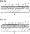
- FIG. 7A is a cross-sectional view with partial omission showing a state in which a dense layer is disposed on another principal surface of the porous ceramic structure;
- FIG. 7B is a cross-sectional view with partial omission showing a state in which part or all of the divided portions of the porous ceramic structure shown in FIG. 7A are separated into divided pieces;
- FIG. 8A is an explanatory diagram with partial omission showing a state in which a plurality of particles are dispersed in a slurry according to a conventional example
- FIG. 8B is an explanatory diagram with partial omission showing a state in which the slurry is dried, fired, and solidified to form a bulk body.
- FIGS. 1A to 8B An example of a porous ceramic structure according to the present invention will be described below with reference to FIGS. 1A to 8B .
- the tilde symbol “ ⁇ ” which indicates a numerical range is used with the implication that the numerical values written before and after the tilde symbol are included therein as a lower limit value and an upper limit value of the numerical range.
- a porous ceramic structure 10 is of a three-dimensional shape, having one principal surface 12 a , another principal surface 12 b opposite to the one principal surface 12 a , and a plurality of side surfaces (for example, four side surfaces 14 a to 14 d ).
- Concerning the shape of the porous ceramic structure 10 at least a planar shape as viewed from the upper surface thereof is a shape along the planar shape of an installation area on a base material (i.e., an object 24 to which a bulk body 22 is applied as shown in FIG. 4A or the like).
- the porous ceramic structure 10 has a rectangular parallelepiped shape for convenience.
- the porous ceramic structure 10 has at least one cut 16 from the one principal surface 12 a toward the other principal surface 12 b .
- one or more cuts 16 may be formed in one direction (e.g., x-direction). Further, one or more cuts 16 may be formed in another direction different from the one direction (e.g., the direction orthogonal to the one direction: y-direction).
- the cuts 16 may be formed to extend linearly from one side surface (e.g., the side surface 14 a or the side surface 14 c ) to another side surface opposite to the one side surface (e.g., the side surface 14 b or the side surface 14 d ), or the cuts 16 may be formed to extend halfway, for example, as a cut 16 b and the like. As shown in FIG. 1B , for example, as a cut 16 a and the like, the cuts 16 may be formed to extend linearly from one side surface (e.g., the side surface 14 a or the side surface 14 c ) to another side surface opposite to the one side surface (e.g., the side surface 14 b or the side surface 14 d ), or the cuts 16 may be formed to extend halfway, for example, as a cut 16 b and the like. As shown in FIG.
- the cuts 16 may be formed along the side surfaces (e.g., the side surface 14 a or the side surface 14 c ) as the cuts 16 a , 16 b and the like, in the x-direction or y-direction, or the cuts 16 may be formed obliquely to the side surfaces (e.g., the side surface 14 b or the side surface 14 d ) as the cuts 16 c , 16 d.
- the porous ceramic structure 10 preferably have an aspect ratio of a divided portion divided by the cuts 16 (hereinafter referred to as a divided portion 18 ) greater than or equal to 3. More preferably, the aspect ratio is greater than or equal to 5, even more preferably, is greater than or equal to 7, and still even more preferably, is greater than or equal to 15.
- the aspect ratio is defined by the maximum length La divided by the minimum length Lb, or La/Lb.
- the maximum length La refers to a maximum length on a widest surface (in this case, a surface belonging to the one principal surface 12 a ) from among the plurality of surfaces constituting the divided portion 18 .
- the maximum length La corresponds to the length of a longest diagonal line
- the maximum length La corresponds to the length of a diameter
- the maximum length La corresponds to the length of a major axis of the ellipse.
- the minimum length Lb refers to a thickness of the thinnest portion of the divided portion 18 , i.e., the thickness ta of the porous ceramic structure 10 .
- the thickness ta preferably is less than or equal to 500 ⁇ m, more preferably, is 50 ⁇ 500 ⁇ m, even more preferably, is 55 ⁇ 400 ⁇ m, and particularly preferably, is 60 ⁇ 300 ⁇ m.
- an end surface 20 of the cut 16 may be inclined. All the cuts 16 may have the same inclination angle ⁇ of the end surface 20 or different angles.
- the inclination angle ⁇ refers to an inclination angle to a direction of the normal line that is normal to the one principal surface 12 a .
- the shape of the cut 16 in a cross section may be a rectangle.
- the relationship between a depth ha of the cut 16 and the thickness ta of the porous ceramic structure 10 is preferably 1/10 ⁇ ha/ta ⁇ 9/10 more preferably, 1/10 ⁇ ha/ta ⁇ 7/10 and even more preferably, 1/10 ⁇ ha/ta ⁇ 1/2
- Curved surfaces may or may not be formed on respective ridge line portions of the four side surfaces 14 a to 14 d.
- porous may refer to a state that is neither dense nor hollow, as well as a state composed of a plurality of pores or grains.
- dense refers to a state in which a plurality of fine grains are bonded without gaps, having no pores.
- hollow refers to a state in which the interior is hollow, and in which an outer shell portion thereof is dense.
- the porosity of the porous ceramic structure 10 is 20% ⁇ 99%.
- the pores include at least one of closed pores and open pores, and may include both closed pores and open pores.
- the shape of the pores i.e., a surface shape of openings thereof, may be of any shape including a square shape, a quadrilateral shape, a triangular shape, a hexagonal shape, a circular shape, etc., or an irregular shape.
- the average pore diameter preferably is less than or equal to 500 nm, and more preferably, is 10 ⁇ 500 nm. This dimension is effective to inhibit the occurrence of lattice vibrations (phonons), which is a primary cause of thermal conductivity.
- the porous ceramic structure 10 has a structure in which fine grains are connected in three dimensions.
- a grain diameter of the fine grains is preferably 1 nm ⁇ 5 ⁇ m. More preferably, the grain diameter is 50 nm ⁇ 1 ⁇ m.
- the porous ceramic structure 10 which is composed of fine grains having such a grain size range, effectively achieves a low thermal conductivity, since the occurrence of lattice vibrations (phonons), which is a primary cause of heat conduction, is inhibited.
- the fine grains may be a grain composed of one crystalline grain (a single crystalline grain), or a grain composed of a large number of crystalline grains (a polycrystalline grain).
- the porous ceramic structure 10 preferably is an aggregation of fine grains having grain diameters lying within the aforementioned ranges.
- the grain diameter of the fine grains is determined by measuring, from an image of an electronic microscopic observation, the size (a diameter in the case of spherical grains, or a maximum diameter otherwise) of one fine grain of the grain groups that make up a framework of the porous ceramic structure 10 .
- the thermal conductivity of the porous ceramic structure 10 is preferably less than 1 W/mK, more preferably, is less than or equal to 0.7 W/mK, even more preferably, is less than or equal to 0.5 W/mK, and particularly preferably, is less than or equal to 0.3 W/mK.
- the constituent material of the porous ceramic structure 10 preferably contains a metal oxide, and more preferably, consists only of a metal oxide. This is because, if such a metal oxide is contained therein, the thermal conductivity tends to be lower, due to the fact that the ion binding property between metal and oxygen is stronger compared to the case of a non-oxide (for example, a carbide or nitride) of a metal.
- a metal oxide for example, a carbide or nitride
- the metal oxide preferably is an oxide of one element or a composite oxide of two or more elements selected from the group consisting of Zr, Y, Al, Si, Ti, Nb, Sr, La, Hf, Ce, Gd, Sm, Mn, Yb, Er, and Ta. This is because, if the metal oxide is an oxide or a composite oxide of such elements, heat conduction due to lattice vibrations (phonons) is unlikely to occur.
- the material include ZrO 2 —Y 2 O 3 to which Gd 2 O 3 , Yb 2 O 3 , Er 2 O 3 , etc., is added.
- ZrO 2 —HfO 2 —Y 2 O 3 ZrO 2 —Y 2 O 3 —La 2 O 3
- ZrO 2 —HfO 2 —Y 2 O 3 La 2 O 3
- HfO 2 —Y 2 O 3 CeO 2 —Y 2 O 3
- Gd 2 Zr 2 O 7 Sm 2 Zr 2 O 7 , LaMnAl 11 O 19 , YTa 3 O 9 , Y 0.7 La 0.3 Ta 3 O 9 , Y 1.08 Ta 2.76 Zr 0.24 O 9 , Y 2 Ti 2 O 7 , LaTa 3 O 9 , Yb 2 Si 2 O 7 , Y 2 Si 2 O 7 , Ti 3 O 5 , and the like.
- step S 1 of FIG. 3A a pore forming agent, a binder, a plasticizer, and a solvent are added to and mixed with a constituent material powder of the aforementioned porous ceramic structure 10 in order to prepare a casting slurry.
- step S 2 the casting slurry is subjected to a vacuum defoaming treatment, whereby the viscosity of the slurry is adjusted.
- the cast body (green sheet, green body) is manufactured by, for example, a doctor blade device, such that a thickness thereof after firing becomes the minimum length Lb.
- step S 3 the cast body (green sheet) is fired, whereby a sheet-shaped sintered body is obtained.
- step S 4 the sintered body is machined with a laser to thereby obtain the porous ceramic structure 10 having the plurality of cuts 16 .
- a laser machining process is performed by causing a laser beam to reach halfway in the thickness direction of the sintered body.
- steps S 101 and S 102 after having prepared a slurry used for casting in the same manner as in steps S 1 and S 2 of FIG. 3A , a cast body (green sheet) is produced so that the thickness thereof after firing becomes the minimum length Lb.
- step S 103 a cast body (green sheet) having a plurality of concavities and convexities therein is produced by machining the cast body (green sheet) with a laser.
- step S 104 the porous ceramic structure 10 having the plurality of cuts 16 therein is obtained by firing the cast body having the plurality of concavities and convexities.
- an adhesive 26 is coated on the object 24 .
- the porous ceramic structure 10 is transferred onto the adhesive 26 of the object 24 , for example, by using a sheet 28 having the porous ceramic structure 10 adhered to one surface thereof.
- Concerning the sheet 28 a sheet or film having an adhesive force, which becomes peelable due to external factors such as heat, electricity, or the like, is preferable.
- the porous ceramic structure 10 may be placed on the adhesive 26 by using the jig directly, without using the sheet 28 .
- a bulk body 22 composed of the porous ceramic structure 10 and the adhesive 26 is installed on the object 24 .
- the bulk body 22 may further be constituted by coating the adhesive 26 onto the porous ceramic structure 10 .
- the adhesive 26 since the outer surface of the porous ceramic structure 10 is covered with the adhesive 26 , although the structural integrity thereof increases in strength, there is a concern that the thermal conductivity may become higher than in the example of FIG. 4C .
- FIG. 5B from the state shown in FIG. 5A , another porous ceramic structure 10 may further be transferred onto the upper layer adhesive 26 to thereby make up the bulk body 22 .
- the bulk body 22 made up from the adhesive 26 and the porous ceramic structure 10 in two layers is installed.
- FIG. 5C from the state shown in FIG. 5B , the bulk body 22 may further be constituted by coating the adhesive 26 onto the upper layer porous ceramic structure 10 .
- part or all of the divided portions 18 of the porous ceramic structure 10 may be separated into divided pieces 30 .
- the plurality of divided pieces 30 can be installed along the surface of the object 24 .
- a dense layer 32 may be disposed on the other principal surface 12 b of the porous ceramic structure 10 .
- the dense layer 32 may be disposed on the one principal surface 12 a (principal surface on the side of the object 24 ) opposite to the other principal surface 12 b .
- dense layers 32 may be disposed on both the one principal surface 12 a and the other principal surface 12 b of the porous ceramic structure 10 .
- the dense layer 32 is disposed on the one principal surface 12 a of the porous ceramic structure 10 , it is possible to inhibit the adhesive 26 from infiltrating into the porous ceramic structure 10 or the divided pieces 30 , and in addition, to increase the strength of the porous ceramic structure 10 or the divided pieces 30 .
- a separately formed dense layer 32 may be disposed on the porous ceramic structure 10 , or an altered layer (dense layer) may be formed in the porous ceramic structure 10 itself.
- the porous ceramic structure 10 is formed in a state that a plurality of portions divided by the cuts 16 , i.e., the plurality of divided portions 18 are put together, the plurality of divided portions 18 can be uniformly distributed and arranged in the adhesive 26 . Also, since regions composed of only the adhesive 26 having a higher thermal conductivity than that of the porous ceramic structure 10 become narrowed, the thermal conductivity of the bulk body 22 can be suppressed to remain at a low value.
- the thermal conductivity can be equalized within the bulk bodies 22 , there is no need to change or modify the bulk body 22 corresponding to the location where the bulk body 22 is installed, the process of arranging the bulk body 22 can be simplified, and the number of arranging steps can be reduced.
- the porous ceramic structure 10 since the porous ceramic structure 10 is installed on the object 24 through the adhesive 26 , a plurality of the divided portions 18 or a plurality of the divided pieces 30 can be arranged uniformly on the object 24 .
- it becomes easy to install the bulk body 22 in a partial region of the object 24 , or to install the bulk body 22 along a complex shape the degree of freedom of design can be enhanced.
- the sheet 28 is used on which the porous ceramic structure 10 is attached on one surface thereof, handling of the porous ceramic structure 10 in which the plurality of cuts 16 are formed is facilitated, while in addition, the operation of installing the porous ceramic structure 10 onto the adhesive 26 is simplified. This is advantageous in terms of simplifying the manufacturing process.
- the adhesive strength (JIS Z0237) of the sheet 28 is greater than or equal to 1.0 N/10 mm, the tensile elongation (JIS K7127) of the sheet 28 is greater than or equal to 0.5%, and the thickness of the sheet 28 is less than or equal to 5 mm. Consequently, the following effects can be obtained.
- the adhesive strength of the sheet 28 exhibits the following properties. More specifically, the adhesive strength at the time that the porous ceramic structure 10 are retained is greater than or equal to 1.0 N/10 mm, and the adhesive strength at the time of peeling the porous ceramic structure 10 is less than or equal to 0.1 N/10 mm.
- the method of evaluating the adhesive strength of the sheet 28 is the same as the method used for evaluating the adhesive strength of an adhesive tape.
- the sheet 28 is attached to a stainless steel plate, and the sheet 28 is pulled at an angle of 180° or 90°, whereupon the force applied when peeling the sheet 28 off from the stainless steel plate is regarded as the adhesive force (adhesive strength).
- the sheet 28 is formed by applying an adhesive to a base material (support).
- a base material preferably a material is selected from among the following.
- the porous ceramic structure 10 when the porous ceramic structure 10 is transferred onto the planar object 24 , it is preferable to use a film, metal foil, paper, or the like as the base material.
- the base material of the sheet 28 since the base material of the sheet 28 is stiff, it is possible to dispose the sheet 28 in the form of a film without wrinkles with respect to the planar object 24 .
- the porous ceramic structure 10 In the case of transferring the porous ceramic structure 10 onto an object 24 having a curved surface (convex surface, concave surface, irregular surface) shape, it is preferable to use a cloth, a rubber sheet, foam or the like as the base material. In this case, since the base material of the sheet 28 is soft and stretchable, it is possible to dispose the sheet 28 in following relation to the curved surface shape of the object 24 .
- the adhesive strength of the sheet 28 can be weakened and the sheet 28 can be easily peeled off.
- the adhesive strength of the sheet 28 is preferably weaker than the adhesive strength of the adhesive 26 that is used between the object 24 and the porous ceramic structure 10 .
- the cuts 16 are formed in the porous ceramic structure 10 . Therefore, for example, as shown in FIG. 5A , when the bulk body 22 is installed on the surface of the object 24 , and even if a surface of the object 24 has an irregular shape (warped or the like), a curved surface, etc., the bulk body 22 can be installed along the surface of the object 24 .
- the porous ceramic structure 10 is hard to be separated into the plurality of divided pieces 30 .
- a surface of the object 24 has an irregular shape (warped or the like), a curved surface, etc., then it is concerned that adhesion of the bulk body 22 to the surface of the object 24 is decreased and the bulk body 22 tends to be peeled off.
- the porous ceramic structure 10 is easy to be separated. Then, handling (conveyance, etc.) of the porous that the porous ceramic structure 10 is hard to be transferred onto the surface of the object 24 by using the sheet 28 . It is also concerned that this leads to complicated steps and reduced productivity.
- the relationship between the depth ha of the cut 16 and the thickness ta of the porous ceramic structure 10 is preferably 1/10 ⁇ ha/ta ⁇ 9/10. More preferably, the relationship is 1/10 ⁇ ha/ta ⁇ 7/10, and even more preferably, is 1/10 ⁇ ha/ta ⁇ 1/2.
- an adhesive 26 thermal conductivity 2 W/mK
- Example 1 a porous ceramic structure for use in measuring porosity, and a porous ceramic structure for use as a bulk body were manufactured in the following manner.
- the porous ceramic structures of the later-described Examples 2 to 4, and Comparative Examples 1 and 2 were also manufactured in a similar manner.
- a pore forming agent (latex particles or melamine resin particles), a polyvinyl butyral resin (PVB) as a binder, DOP (dioctyl phthalate) as a plasticizer, and xylene and 1-butanol as solvents were added to yttria-partially-stabilized zirconia powder, and mixed in a ball mill for 30 hours in order to prepare a slurry for casting a green sheet.
- the slurry was subjected to a vacuum defoaming treatment, whereby the viscosity thereof was adjusted to 4000 cps, and thereafter, the cast body (green sheet) was produced by a doctor blade device such that a thickness thereof after firing was of a minimum length. Thereafter, the cast body was fired at 1100° C. for one hour in order to obtain the sintered body.
- the sintered body was machined by a laser to make cuts, thereby obtaining the porous ceramic structure 10 .
- the porous ceramic structure 10 for use in measuring porosity was separated into a plurality of divided pieces 30 .
- Ten divided pieces 30 were selected at random from among the plurality of divided pieces 30 and embedded in a resin.
- the resin was polished to create an observation site where the divided pieces 30 could be observed with an electron microscope, to thereby obtain a resin-filled polished surface.
- an electron microscopic observation was performed on the resin-filled polished surface. From such an image analysis, the porosities of the ten divided pieces 30 were calculated, and the average value of the ten divided pieces 30 was taken as the porosity of the porous ceramic structure 10 .
- the average pore diameter of the porous ceramic structure 10 was measured using an automated porosimeter (trade name “Autopore 9200”) by Shimadzu Corporation.
- the density of the bulk body 22 was measured with a mercury porosimeter.
- the specific heat of the bulk body 22 was measured using a DSC (Differential Scanning calorimeter) method.
- the adhesion of the bulk body 22 to the object 24 was evaluated.
- the evaluation “x” was given, and when the bulk body 22 was not peeled off, the evaluation “ ⁇ ” was given.
- the thermal conductivity of the bulk body 22 was not measured.
- Example 1 Porous Ceramic Structure Bulk Body Minimum Thermal Porosity Length Aspect Peeling Conductivity (%) ( ⁇ m) Ratio ha/ta Test (W/mK) Evaluation
- Example 1 60 50 10 1/2 ⁇ 0.8 A
- Example 2 60 100 5 1/2 ⁇ 0.4 A
- Example 3 75 80 7 1/7 ⁇ 0.3
- Example 4 30 100 5 1/2 ⁇ 1.0 B Comparative 10 50 10 1/2 ⁇ 1.8 C
- Example 1 Comparative 60 50 10 1/20 X — —
- Example 2 Example 2
- Comparative Example 2 the bulk body 22 was peeled off in the tape peeling test. It is considered that the adhesion was reduced because the depth ha of the cut 16 was too shallow and the bulk body 22 could not follow the surface shape of the object 24 . Thus, concerning Comparative Example 2, the thermal conductivity of the bulk body 22 was not measured or evaluated.
- Comparative Example 1 The thermal conductivity of Comparative Example 1 was high at 1.8 W/mK. It is considered that the thermal conductivity was high because in the bulk body 22 according to Comparative Example 1, many regions existed in which only the adhesive 26 was present.
- Example 4 the thermal conductivities of the bulk bodies 22 were all less than or equal to 0.9 W/mK, and the evaluation therefor was A. Concerning Example 4 as well, although the evaluation was B, the thermal conductivity was 1.0 W/mK, which was exceedingly close to the evaluation result of A.
- porous ceramic structure according to the present invention is not limited to the above-described embodiments, and it is a matter of course that various configurations could be adopted therein without departing from the gist of the present invention.
Landscapes
- Chemical & Material Sciences (AREA)
- Engineering & Computer Science (AREA)
- Ceramic Engineering (AREA)
- Structural Engineering (AREA)
- Materials Engineering (AREA)
- Organic Chemistry (AREA)
- Manufacturing & Machinery (AREA)
- Inorganic Chemistry (AREA)
- Nanotechnology (AREA)
- Composite Materials (AREA)
- Mechanical Engineering (AREA)
- Chemical Kinetics & Catalysis (AREA)
- Porous Artificial Stone Or Porous Ceramic Products (AREA)
- Laminated Bodies (AREA)
- Devices For Post-Treatments, Processing, Supply, Discharge, And Other Processes (AREA)
- Producing Shaped Articles From Materials (AREA)
Abstract
Description
1/10≤ha/ta≤9/10
more preferably,
1/10≤ha/ta≤7/10
and even more preferably,
1/10≤ha/ta≤1/2
Thermal Diffusivity×Specific Heat×Density=Thermal Conductivity
Then, based on the following evaluation criteria, the thermal conductivities of Examples 1 to 4 and Comparative Examples 1 and 2 were evaluated.
| TABLE 1 | ||||
| Porous Ceramic Structure | Bulk Body | |||
| Minimum | Thermal | |||||||
| Porosity | Length | Aspect | Peeling | Conductivity | ||||
| (%) | (μm) | Ratio | ha/ta | Test | (W/mK) | Evaluation | ||
| Example 1 | 60 | 50 | 10 | 1/2 | ◯ | 0.8 | A |
| Example 2 | 60 | 100 | 5 | 1/2 | ◯ | 0.4 | A |
| Example 3 | 75 | 80 | 7 | 1/7 | ◯ | 0.3 | A |
| Example 4 | 30 | 100 | 5 | 1/2 | ◯ | 1.0 | |
| Comparative | |||||||
| 10 | 50 | 10 | 1/2 | ◯ | 1.8 | C | |
| Example 1 | |||||||
| Comparative | 60 | 50 | 10 | 1/20 | X | — | — |
| Example 2 | |||||||
Claims (5)
Applications Claiming Priority (5)
| Application Number | Priority Date | Filing Date | Title |
|---|---|---|---|
| JP2015141897 | 2015-07-16 | ||
| JP2015-141897 | 2015-07-16 | ||
| JP2015235495 | 2015-12-02 | ||
| JP2015-235495 | 2015-12-02 | ||
| PCT/JP2016/066506 WO2017010185A1 (en) | 2015-07-16 | 2016-06-02 | Porous ceramic structure |
Related Parent Applications (1)
| Application Number | Title | Priority Date | Filing Date |
|---|---|---|---|
| PCT/JP2016/066506 Continuation WO2017010185A1 (en) | 2015-07-16 | 2016-06-02 | Porous ceramic structure |
Publications (2)
| Publication Number | Publication Date |
|---|---|
| US20180141872A1 US20180141872A1 (en) | 2018-05-24 |
| US10597336B2 true US10597336B2 (en) | 2020-03-24 |
Family
ID=57756920
Family Applications (2)
| Application Number | Title | Priority Date | Filing Date |
|---|---|---|---|
| US15/869,554 Active US10597336B2 (en) | 2015-07-16 | 2018-01-12 | Porous ceramic structure |
| US15/869,611 Expired - Fee Related US10611696B2 (en) | 2015-07-16 | 2018-01-12 | Porous ceramic structure |
Family Applications After (1)
| Application Number | Title | Priority Date | Filing Date |
|---|---|---|---|
| US15/869,611 Expired - Fee Related US10611696B2 (en) | 2015-07-16 | 2018-01-12 | Porous ceramic structure |
Country Status (5)
| Country | Link |
|---|---|
| US (2) | US10597336B2 (en) |
| JP (4) | JP6231721B2 (en) |
| CN (2) | CN107848899A (en) |
| DE (2) | DE112016003205B9 (en) |
| WO (2) | WO2017010185A1 (en) |
Families Citing this family (4)
| Publication number | Priority date | Publication date | Assignee | Title |
|---|---|---|---|---|
| WO2018020860A1 (en) * | 2016-07-29 | 2018-02-01 | 日本碍子株式会社 | Porous ceramic particles and porous ceramic structure |
| CN110461798A (en) * | 2017-03-29 | 2019-11-15 | 日本碍子株式会社 | Porous ceramic particle and porous ceramic structure |
| JP7133916B2 (en) * | 2017-10-18 | 2022-09-09 | 日本碍子株式会社 | Heat dissipating member, heat dissipating structure and electronic device |
| WO2020061234A1 (en) * | 2018-09-19 | 2020-03-26 | Akash Systems, Inc. | Systems and methods for satellite communication |
Citations (12)
| Publication number | Priority date | Publication date | Assignee | Title |
|---|---|---|---|---|
| JPH05309638A (en) | 1992-05-01 | 1993-11-22 | Kubota Corp | Unevenness patterning method on surface of cement sheet material |
| JPH07164417A (en) | 1993-12-15 | 1995-06-27 | Murata Mfg Co Ltd | Production fo ceramic green sheet |
| US5618765A (en) * | 1993-05-20 | 1997-04-08 | Sumitomo Electric Industries, Ltd. | Ceramics porous body and method of preparing the same |
| JPH11216713A (en) | 1998-01-30 | 1999-08-10 | Nichiha Corp | Inorganic plate |
| JP2000202819A (en) | 1999-01-11 | 2000-07-25 | Sumitomo Metal Electronics Devices Inc | Green sheet of two-piece structure |
| JP2002176119A (en) | 2000-12-06 | 2002-06-21 | Toshiba Corp | Silicon nitride substrate, silicon nitride circuit board using the same, and method of manufacturing the same |
| JP2004010903A (en) | 2003-10-06 | 2004-01-15 | Nagashima Tokushu Toryo Kk | Thermal insulation coating |
| JP2006173368A (en) | 2004-12-16 | 2006-06-29 | Sony Corp | Ceramic substrate |
| US20070130897A1 (en) * | 2005-11-18 | 2007-06-14 | Hiroshi Sakaguchi | Honeycomb structured body, method for manufacturing honeycomb structured body, and exhaust gas purifying device |
| JP2010064945A (en) | 2008-09-12 | 2010-03-25 | Toyohashi Univ Of Technology | Method for manufacturing ceramic composite particle and functional ceramic composite particle |
| JP2010155946A (en) | 2008-12-29 | 2010-07-15 | Dow Corning Toray Co Ltd | Curable organopolysiloxane composition and porous organopolysiloxane cured product |
| US20150104626A1 (en) * | 2012-06-20 | 2015-04-16 | Ngk Insulators, Ltd. | Porous Plate-Shaped Filler, Coating Composition, Heat-Insulating Film, and Heat-Insulating Film Structure |
Family Cites Families (11)
| Publication number | Priority date | Publication date | Assignee | Title |
|---|---|---|---|---|
| JPS5413621A (en) * | 1977-07-01 | 1979-02-01 | Kubota Ltd | Ornamental roof material and making method thereof |
| JPS62232187A (en) * | 1986-04-02 | 1987-10-12 | 松下電器産業株式会社 | Ceramic substrate manufacturing method |
| JP4398142B2 (en) * | 2001-12-07 | 2010-01-13 | 日本碍子株式会社 | Porous ceramic body and method for producing glass used for the binder |
| CN1906141B (en) * | 2004-12-27 | 2010-11-03 | 揖斐电株式会社 | Honeycomb structure and sealing material layer |
| BRPI0621318B1 (en) * | 2006-02-10 | 2017-10-10 | Saint-Gobain Ceramics & Plastics, Inc | PROCESS FOR THE MANUFACTURE OF POROSA CERAMIC MATERIAL |
| BRPI0916391A2 (en) * | 2008-07-22 | 2019-03-06 | Saint Gobain Abrasifs Sa | coated abrasives containing aggregates |
| JP5495545B2 (en) * | 2008-08-28 | 2014-05-21 | 京セラ株式会社 | Porous ceramic member, method for producing the same, and filter |
| CN105713568B (en) * | 2010-11-01 | 2018-07-03 | 3M创新有限公司 | It is used to prepare the laser method, shaped ceramic abrasive grain and abrasive product of shaped ceramic abrasive grain |
| JP5559023B2 (en) * | 2010-12-15 | 2014-07-23 | 日本特殊陶業株式会社 | Wiring board and manufacturing method thereof |
| JP2013102035A (en) * | 2011-11-08 | 2013-05-23 | Ngk Spark Plug Co Ltd | Ceramic substrate and manufacturing method thereof |
| WO2014071346A1 (en) * | 2012-11-05 | 2014-05-08 | University Of Virginia Patent Foundation | Porous metal ceramic materials and methods for making and using the same |
-
2016
- 2016-06-02 DE DE112016003205.6T patent/DE112016003205B9/en not_active Expired - Fee Related
- 2016-06-02 JP JP2017506416A patent/JP6231721B2/en active Active
- 2016-06-02 WO PCT/JP2016/066506 patent/WO2017010185A1/en not_active Ceased
- 2016-06-02 WO PCT/JP2016/066507 patent/WO2017010186A1/en not_active Ceased
- 2016-06-02 CN CN201680041453.6A patent/CN107848899A/en active Pending
- 2016-06-02 CN CN201680041452.1A patent/CN107835796B/en active Active
- 2016-06-02 DE DE112016003197.1T patent/DE112016003197B4/en active Active
- 2016-06-02 JP JP2017506418A patent/JP6220099B2/en active Active
-
2017
- 2017-09-28 JP JP2017187334A patent/JP2018016541A/en active Pending
- 2017-10-19 JP JP2017202464A patent/JP2018058758A/en active Pending
-
2018
- 2018-01-12 US US15/869,554 patent/US10597336B2/en active Active
- 2018-01-12 US US15/869,611 patent/US10611696B2/en not_active Expired - Fee Related
Patent Citations (13)
| Publication number | Priority date | Publication date | Assignee | Title |
|---|---|---|---|---|
| JPH05309638A (en) | 1992-05-01 | 1993-11-22 | Kubota Corp | Unevenness patterning method on surface of cement sheet material |
| US5618765A (en) * | 1993-05-20 | 1997-04-08 | Sumitomo Electric Industries, Ltd. | Ceramics porous body and method of preparing the same |
| JPH07164417A (en) | 1993-12-15 | 1995-06-27 | Murata Mfg Co Ltd | Production fo ceramic green sheet |
| JPH11216713A (en) | 1998-01-30 | 1999-08-10 | Nichiha Corp | Inorganic plate |
| JP2000202819A (en) | 1999-01-11 | 2000-07-25 | Sumitomo Metal Electronics Devices Inc | Green sheet of two-piece structure |
| JP2002176119A (en) | 2000-12-06 | 2002-06-21 | Toshiba Corp | Silicon nitride substrate, silicon nitride circuit board using the same, and method of manufacturing the same |
| JP2004010903A (en) | 2003-10-06 | 2004-01-15 | Nagashima Tokushu Toryo Kk | Thermal insulation coating |
| JP2006173368A (en) | 2004-12-16 | 2006-06-29 | Sony Corp | Ceramic substrate |
| US20070130897A1 (en) * | 2005-11-18 | 2007-06-14 | Hiroshi Sakaguchi | Honeycomb structured body, method for manufacturing honeycomb structured body, and exhaust gas purifying device |
| JP2010064945A (en) | 2008-09-12 | 2010-03-25 | Toyohashi Univ Of Technology | Method for manufacturing ceramic composite particle and functional ceramic composite particle |
| JP2010155946A (en) | 2008-12-29 | 2010-07-15 | Dow Corning Toray Co Ltd | Curable organopolysiloxane composition and porous organopolysiloxane cured product |
| US20120009412A1 (en) | 2008-12-29 | 2012-01-12 | Makoto Iwai | Curable Organopolysiloxane Composition And Porous Cured Organopolysiloxane Material |
| US20150104626A1 (en) * | 2012-06-20 | 2015-04-16 | Ngk Insulators, Ltd. | Porous Plate-Shaped Filler, Coating Composition, Heat-Insulating Film, and Heat-Insulating Film Structure |
Non-Patent Citations (2)
| Title |
|---|
| International Search Report and Written Opinion (Application No. PCT/JP2016/066506) dated Aug. 9, 2016. |
| Japanese Office Action (Application No. 2017-506416) dated Apr. 27, 2017 (with English translation). |
Also Published As
| Publication number | Publication date |
|---|---|
| WO2017010185A1 (en) | 2017-01-19 |
| DE112016003205B4 (en) | 2019-05-09 |
| CN107835796A (en) | 2018-03-23 |
| DE112016003197T5 (en) | 2018-04-05 |
| US20180141872A1 (en) | 2018-05-24 |
| DE112016003205B9 (en) | 2019-08-29 |
| WO2017010186A1 (en) | 2017-01-19 |
| DE112016003197B4 (en) | 2025-11-20 |
| JPWO2017010186A1 (en) | 2017-07-13 |
| JP2018016541A (en) | 2018-02-01 |
| JP6220099B2 (en) | 2017-10-25 |
| JP2018058758A (en) | 2018-04-12 |
| JPWO2017010185A1 (en) | 2017-07-20 |
| DE112016003205T5 (en) | 2018-04-05 |
| CN107835796B (en) | 2020-12-01 |
| JP6231721B2 (en) | 2017-11-15 |
| US10611696B2 (en) | 2020-04-07 |
| US20180134631A1 (en) | 2018-05-17 |
| CN107848899A (en) | 2018-03-27 |
Similar Documents
| Publication | Publication Date | Title |
|---|---|---|
| US10597336B2 (en) | Porous ceramic structure | |
| EP3075719B1 (en) | Porous material and heat insulating film | |
| US10317004B2 (en) | Porous plate-shaped filler, heat insulation film, and method for producing porous plate-shaped filler | |
| EP3100994A1 (en) | Porous plate-shaped filler | |
| US10745326B2 (en) | Porous ceramic structure | |
| US20170349497A1 (en) | Porous ceramic structure and method of manufacturing the same | |
| JP2019075507A (en) | Heat dissipation member, heat dissipation structure, and electronic device | |
| US20190152862A1 (en) | Porous ceramic particle and porous ceramic structure | |
| US20200002237A1 (en) | Porous ceramic particle and porous ceramic structure | |
| US10590004B2 (en) | Porous ceramic particles | |
| JP6648994B2 (en) | Method for producing composite particle body and fired body |
Legal Events
| Date | Code | Title | Description |
|---|---|---|---|
| AS | Assignment |
Owner name: NGK INSULATORS, LTD., JAPAN Free format text: ASSIGNMENT OF ASSIGNORS INTEREST;ASSIGNORS:KOBAYASHI, HIROHARU;TOMITA, TAKAHIRO;ORIBE, AKINOBU;REEL/FRAME:044608/0032 Effective date: 20171218 |
|
| FEPP | Fee payment procedure |
Free format text: ENTITY STATUS SET TO UNDISCOUNTED (ORIGINAL EVENT CODE: BIG.); ENTITY STATUS OF PATENT OWNER: LARGE ENTITY |
|
| STPP | Information on status: patent application and granting procedure in general |
Free format text: NON FINAL ACTION MAILED |
|
| STPP | Information on status: patent application and granting procedure in general |
Free format text: RESPONSE TO NON-FINAL OFFICE ACTION ENTERED AND FORWARDED TO EXAMINER |
|
| STPP | Information on status: patent application and granting procedure in general |
Free format text: FINAL REJECTION MAILED |
|
| STPP | Information on status: patent application and granting procedure in general |
Free format text: RESPONSE AFTER FINAL ACTION FORWARDED TO EXAMINER |
|
| STPP | Information on status: patent application and granting procedure in general |
Free format text: NOTICE OF ALLOWANCE MAILED -- APPLICATION RECEIVED IN OFFICE OF PUBLICATIONS |
|
| STPP | Information on status: patent application and granting procedure in general |
Free format text: PUBLICATIONS -- ISSUE FEE PAYMENT VERIFIED |
|
| STCF | Information on status: patent grant |
Free format text: PATENTED CASE |
|
| MAFP | Maintenance fee payment |
Free format text: PAYMENT OF MAINTENANCE FEE, 4TH YEAR, LARGE ENTITY (ORIGINAL EVENT CODE: M1551); ENTITY STATUS OF PATENT OWNER: LARGE ENTITY Year of fee payment: 4 |