US10596524B2 - Hollow fiber membrane - Google Patents
Hollow fiber membrane Download PDFInfo
- Publication number
- US10596524B2 US10596524B2 US15/038,931 US201415038931A US10596524B2 US 10596524 B2 US10596524 B2 US 10596524B2 US 201415038931 A US201415038931 A US 201415038931A US 10596524 B2 US10596524 B2 US 10596524B2
- Authority
- US
- United States
- Prior art keywords
- layer
- fiber membrane
- hollow fiber
- porosity
- hollow
- Prior art date
- Legal status (The legal status is an assumption and is not a legal conclusion. Google has not performed a legal analysis and makes no representation as to the accuracy of the status listed.)
- Active, expires
Links
- 239000012528 membrane Substances 0.000 title claims abstract description 80
- 239000012510 hollow fiber Substances 0.000 title claims abstract description 72
- XLYOFNOQVPJJNP-UHFFFAOYSA-N water Substances O XLYOFNOQVPJJNP-UHFFFAOYSA-N 0.000 claims abstract description 33
- 239000011148 porous material Substances 0.000 claims abstract description 20
- 239000000356 contaminant Substances 0.000 claims abstract description 18
- 230000003247 decreasing effect Effects 0.000 claims abstract description 9
- 230000035699 permeability Effects 0.000 claims description 22
- 229920000642 polymer Polymers 0.000 claims description 6
- 239000004695 Polyether sulfone Substances 0.000 claims description 4
- 229920002492 poly(sulfone) Polymers 0.000 claims description 4
- 229920006393 polyether sulfone Polymers 0.000 claims description 4
- 239000012530 fluid Substances 0.000 claims 3
- 238000001914 filtration Methods 0.000 description 15
- 230000007423 decrease Effects 0.000 description 5
- 238000000034 method Methods 0.000 description 5
- 230000000052 comparative effect Effects 0.000 description 4
- 238000011109 contamination Methods 0.000 description 3
- 238000012986 modification Methods 0.000 description 3
- 230000004048 modification Effects 0.000 description 3
- 230000014509 gene expression Effects 0.000 description 2
- 241000700605 Viruses Species 0.000 description 1
- 230000008859 change Effects 0.000 description 1
- 239000000470 constituent Substances 0.000 description 1
- 239000003651 drinking water Substances 0.000 description 1
- 235000020188 drinking water Nutrition 0.000 description 1
- 230000001747 exhibiting effect Effects 0.000 description 1
- 230000007774 longterm Effects 0.000 description 1
- 238000012423 maintenance Methods 0.000 description 1
- 238000004519 manufacturing process Methods 0.000 description 1
- 238000005259 measurement Methods 0.000 description 1
- 238000001471 micro-filtration Methods 0.000 description 1
- 238000001728 nano-filtration Methods 0.000 description 1
- 238000005191 phase separation Methods 0.000 description 1
- 230000002035 prolonged effect Effects 0.000 description 1
- 239000008213 purified water Substances 0.000 description 1
- 230000009467 reduction Effects 0.000 description 1
- 238000001223 reverse osmosis Methods 0.000 description 1
- 238000000926 separation method Methods 0.000 description 1
- 239000002904 solvent Substances 0.000 description 1
- 238000002145 thermally induced phase separation Methods 0.000 description 1
- 238000000108 ultra-filtration Methods 0.000 description 1
- 238000005406 washing Methods 0.000 description 1
Images


Classifications
-
- B—PERFORMING OPERATIONS; TRANSPORTING
- B01—PHYSICAL OR CHEMICAL PROCESSES OR APPARATUS IN GENERAL
- B01D—SEPARATION
- B01D69/00—Semi-permeable membranes for separation processes or apparatus characterised by their form, structure or properties; Manufacturing processes specially adapted therefor
- B01D69/08—Hollow fibre membranes
-
- B—PERFORMING OPERATIONS; TRANSPORTING
- B01—PHYSICAL OR CHEMICAL PROCESSES OR APPARATUS IN GENERAL
- B01D—SEPARATION
- B01D61/00—Processes of separation using semi-permeable membranes, e.g. dialysis, osmosis or ultrafiltration; Apparatus, accessories or auxiliary operations specially adapted therefor
- B01D61/02—Reverse osmosis; Hyperfiltration ; Nanofiltration
- B01D61/025—Reverse osmosis; Hyperfiltration
-
- B—PERFORMING OPERATIONS; TRANSPORTING
- B01—PHYSICAL OR CHEMICAL PROCESSES OR APPARATUS IN GENERAL
- B01D—SEPARATION
- B01D61/00—Processes of separation using semi-permeable membranes, e.g. dialysis, osmosis or ultrafiltration; Apparatus, accessories or auxiliary operations specially adapted therefor
- B01D61/02—Reverse osmosis; Hyperfiltration ; Nanofiltration
- B01D61/027—Nanofiltration
-
- B—PERFORMING OPERATIONS; TRANSPORTING
- B01—PHYSICAL OR CHEMICAL PROCESSES OR APPARATUS IN GENERAL
- B01D—SEPARATION
- B01D61/00—Processes of separation using semi-permeable membranes, e.g. dialysis, osmosis or ultrafiltration; Apparatus, accessories or auxiliary operations specially adapted therefor
- B01D61/14—Ultrafiltration; Microfiltration
- B01D61/145—Ultrafiltration
-
- B—PERFORMING OPERATIONS; TRANSPORTING
- B01—PHYSICAL OR CHEMICAL PROCESSES OR APPARATUS IN GENERAL
- B01D—SEPARATION
- B01D61/00—Processes of separation using semi-permeable membranes, e.g. dialysis, osmosis or ultrafiltration; Apparatus, accessories or auxiliary operations specially adapted therefor
- B01D61/14—Ultrafiltration; Microfiltration
- B01D61/147—Microfiltration
-
- B—PERFORMING OPERATIONS; TRANSPORTING
- B01—PHYSICAL OR CHEMICAL PROCESSES OR APPARATUS IN GENERAL
- B01D—SEPARATION
- B01D69/00—Semi-permeable membranes for separation processes or apparatus characterised by their form, structure or properties; Manufacturing processes specially adapted therefor
- B01D69/02—Semi-permeable membranes for separation processes or apparatus characterised by their form, structure or properties; Manufacturing processes specially adapted therefor characterised by their properties
-
- B—PERFORMING OPERATIONS; TRANSPORTING
- B01—PHYSICAL OR CHEMICAL PROCESSES OR APPARATUS IN GENERAL
- B01D—SEPARATION
- B01D69/00—Semi-permeable membranes for separation processes or apparatus characterised by their form, structure or properties; Manufacturing processes specially adapted therefor
- B01D69/12—Composite membranes; Ultra-thin membranes
- B01D69/1214—Chemically bonded layers, e.g. cross-linking
-
- B—PERFORMING OPERATIONS; TRANSPORTING
- B01—PHYSICAL OR CHEMICAL PROCESSES OR APPARATUS IN GENERAL
- B01D—SEPARATION
- B01D69/00—Semi-permeable membranes for separation processes or apparatus characterised by their form, structure or properties; Manufacturing processes specially adapted therefor
- B01D69/12—Composite membranes; Ultra-thin membranes
- B01D69/1216—Three or more layers
-
- B—PERFORMING OPERATIONS; TRANSPORTING
- B01—PHYSICAL OR CHEMICAL PROCESSES OR APPARATUS IN GENERAL
- B01D—SEPARATION
- B01D71/00—Semi-permeable membranes for separation processes or apparatus characterised by the material; Manufacturing processes specially adapted therefor
- B01D71/06—Organic material
- B01D71/66—Polymers having sulfur in the main chain, with or without nitrogen, oxygen or carbon only
- B01D71/68—Polysulfones; Polyethersulfones
-
- B—PERFORMING OPERATIONS; TRANSPORTING
- B01—PHYSICAL OR CHEMICAL PROCESSES OR APPARATUS IN GENERAL
- B01D—SEPARATION
- B01D2325/00—Details relating to properties of membranes
- B01D2325/02—Details relating to pores or porosity of the membranes
-
- B—PERFORMING OPERATIONS; TRANSPORTING
- B01—PHYSICAL OR CHEMICAL PROCESSES OR APPARATUS IN GENERAL
- B01D—SEPARATION
- B01D2325/00—Details relating to properties of membranes
- B01D2325/02—Details relating to pores or porosity of the membranes
- B01D2325/022—Asymmetric membranes
-
- B—PERFORMING OPERATIONS; TRANSPORTING
- B01—PHYSICAL OR CHEMICAL PROCESSES OR APPARATUS IN GENERAL
- B01D—SEPARATION
- B01D2325/00—Details relating to properties of membranes
- B01D2325/02—Details relating to pores or porosity of the membranes
- B01D2325/022—Asymmetric membranes
- B01D2325/0231—Dense layers being placed on the outer side of the cross-section
-
- B—PERFORMING OPERATIONS; TRANSPORTING
- B01—PHYSICAL OR CHEMICAL PROCESSES OR APPARATUS IN GENERAL
- B01D—SEPARATION
- B01D2325/00—Details relating to properties of membranes
- B01D2325/02—Details relating to pores or porosity of the membranes
- B01D2325/0283—Pore size
- B01D2325/02833—Pore size more than 10 and up to 100 nm
-
- B—PERFORMING OPERATIONS; TRANSPORTING
- B01—PHYSICAL OR CHEMICAL PROCESSES OR APPARATUS IN GENERAL
- B01D—SEPARATION
- B01D2325/00—Details relating to properties of membranes
- B01D2325/04—Characteristic thickness
-
- B—PERFORMING OPERATIONS; TRANSPORTING
- B01—PHYSICAL OR CHEMICAL PROCESSES OR APPARATUS IN GENERAL
- B01D—SEPARATION
- B01D2325/00—Details relating to properties of membranes
- B01D2325/24—Mechanical properties, e.g. strength
-
- B—PERFORMING OPERATIONS; TRANSPORTING
- B01—PHYSICAL OR CHEMICAL PROCESSES OR APPARATUS IN GENERAL
- B01D—SEPARATION
- B01D69/00—Semi-permeable membranes for separation processes or apparatus characterised by their form, structure or properties; Manufacturing processes specially adapted therefor
- B01D69/12—Composite membranes; Ultra-thin membranes
Definitions
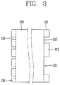
- the first layer 110 is formed within 20 ⁇ m towards the inside cross-section from the outermost part of the hollow fiber membrane 100 exposed to the outside
- the third layer 130 is formed within 20 ⁇ m towards the outside from the outermost part of the hollow part 140 in a radial direction.
Landscapes
- Chemical & Material Sciences (AREA)
- Chemical Kinetics & Catalysis (AREA)
- Engineering & Computer Science (AREA)
- Water Supply & Treatment (AREA)
- Nanotechnology (AREA)
- Separation Using Semi-Permeable Membranes (AREA)
Abstract
Description
Claims (5)
Applications Claiming Priority (3)
| Application Number | Priority Date | Filing Date | Title |
|---|---|---|---|
| KR10-2013-0160586 | 2013-12-20 | ||
| KR1020130160586A KR102140264B1 (en) | 2013-12-20 | 2013-12-20 | Hollow fiber membrane |
| PCT/KR2014/006719 WO2015093705A1 (en) | 2013-12-20 | 2014-07-23 | Hollow fiber membrane |
Publications (2)
| Publication Number | Publication Date |
|---|---|
| US20170001152A1 US20170001152A1 (en) | 2017-01-05 |
| US10596524B2 true US10596524B2 (en) | 2020-03-24 |
Family
ID=53403025
Family Applications (1)
| Application Number | Title | Priority Date | Filing Date |
|---|---|---|---|
| US15/038,931 Active 2035-07-29 US10596524B2 (en) | 2013-12-20 | 2014-07-23 | Hollow fiber membrane |
Country Status (7)
| Country | Link |
|---|---|
| US (1) | US10596524B2 (en) |
| EP (1) | EP3085433A4 (en) |
| JP (1) | JP6273014B2 (en) |
| KR (1) | KR102140264B1 (en) |
| CN (1) | CN105828920B (en) |
| AU (1) | AU2014367656A1 (en) |
| WO (1) | WO2015093705A1 (en) |
Families Citing this family (5)
| Publication number | Priority date | Publication date | Assignee | Title |
|---|---|---|---|---|
| CN109070010B (en) | 2016-03-11 | 2021-09-10 | 旭化成株式会社 | Porous membrane, porous membrane module, method for producing porous membrane, method for producing clarified liquid, and method for producing beer |
| KR102017195B1 (en) * | 2016-11-11 | 2019-09-02 | 주식회사 엘지화학 | Hollow fiber membrane |
| CN109133267B (en) * | 2018-09-06 | 2021-11-12 | 偶极医药科技(徐州)有限公司 | Electrodialysis device for purifying phenylalanine |
| CN115382397B (en) * | 2022-08-22 | 2024-07-02 | 国能龙源环保南京有限公司 | Hollow fiber membrane modules and methods of use |
| CN115259331B (en) * | 2022-08-26 | 2023-09-08 | 中国科学院生态环境研究中心 | Membrane contact reactor and treatment system for wastewater deamination |
Citations (22)
| Publication number | Priority date | Publication date | Assignee | Title |
|---|---|---|---|---|
| JPS61200805A (en) | 1985-03-01 | 1986-09-05 | Teijin Ltd | Polyether sulfone microporous hollow yarn membrane and its production |
| US4629563A (en) | 1980-03-14 | 1986-12-16 | Brunswick Corporation | Asymmetric membranes |
| JPH02251233A (en) | 1989-03-22 | 1990-10-09 | Asahi Chem Ind Co Ltd | Polysulfone-based hollow yarn membrane and its preparation |
| US5895573A (en) | 1996-10-07 | 1999-04-20 | Prime Water Systems N.V. | Ultrafiltration device for domestic/drinking water purification |
| US20020011443A1 (en) * | 2000-06-21 | 2002-01-31 | Kuraray Co., Ltd. | Porous hollow fiber membranes and method of making the same |
| WO2003026779A1 (en) | 2001-08-01 | 2003-04-03 | Asahi Kasei Kabushiki Kaisha | Multilayer microporous film |
| US6663805B1 (en) | 2002-09-20 | 2003-12-16 | L'air Liquide Societe Anonyme A Directoire Et Conseil De Surveillance Pour L'etude Et L'exploitation Des Procedes Georges Claude | Process for making hollow fiber mixed matrix membranes |
| US20060107639A1 (en) * | 2004-10-15 | 2006-05-25 | Hamlin Thomas J | Pleated multi-layer filter media and cartridge |
| JP3868479B2 (en) | 2004-03-17 | 2007-01-17 | 株式会社物産ナノテク研究所 | Separation membrane |
| WO2007022576A1 (en) | 2005-08-22 | 2007-03-01 | Siemens Water Technologies Corp. | An assembly for water filtration using a tube manifold to minimise backwash |
| JP2007289886A (en) | 2006-04-26 | 2007-11-08 | Toyobo Co Ltd | Polymeric porous hollow fiber membrane |
| KR20080071015A (en) | 2007-01-29 | 2008-08-01 | 정덕수 | Asymmetric multilayer ceramic filter and its manufacturing method and water purification system using the same |
| JP2009536090A (en) | 2006-05-06 | 2009-10-08 | メムブラーナ ゲゼルシャフト ミット ベシュレンクテル ハフツング | Ultrafiltration membrane |
| JP2010506709A (en) | 2006-10-18 | 2010-03-04 | ガンブロ・ルンディア・エービー | Hollow fiber membrane and method for producing hollow fiber membrane |
| EP2221102A1 (en) | 2007-10-19 | 2010-08-25 | Toyo Boseki Kabushiki Kaisha | Hollow fiber membrane for treating liquids |
| WO2011021300A1 (en) | 2009-08-21 | 2011-02-24 | 東レ株式会社 | Water-vapor-permeable membrane, hollow-fiber membrane, and hollow-fiber membrane module |
| JP2011078920A (en) | 2009-10-08 | 2011-04-21 | Toyobo Co Ltd | Permselective hollow fiber membrane |
| US20120125850A1 (en) * | 2010-04-16 | 2012-05-24 | Asahi Kasei Chemicals Corporation | Deformed porous hollow fiber membrane, production method of deformed porous hollow fiber membrane, and module, filtration device, and water treatment method in which deformed porous hollow fiber membrane is used |
| JP5097298B2 (en) | 2010-03-04 | 2012-12-12 | 積水化学工業株式会社 | Polymer water treatment membrane, method for producing the same and water treatment method |
| WO2013039456A1 (en) | 2011-09-14 | 2013-03-21 | National University Of Singapore | A thin film nanofiltration membrane |
| US20130092622A1 (en) | 2011-04-01 | 2013-04-18 | Millipore Corporation | Nanofiber containing composite membrane structures |
| US20130340613A1 (en) * | 2012-06-20 | 2013-12-26 | Hollingsworth & Vose Company | Absorbent and/or adsorptive filter media |
-
2013
- 2013-12-20 KR KR1020130160586A patent/KR102140264B1/en active Active
-
2014
- 2014-07-23 EP EP14870848.0A patent/EP3085433A4/en not_active Withdrawn
- 2014-07-23 WO PCT/KR2014/006719 patent/WO2015093705A1/en not_active Ceased
- 2014-07-23 CN CN201480068987.9A patent/CN105828920B/en active Active
- 2014-07-23 US US15/038,931 patent/US10596524B2/en active Active
- 2014-07-23 AU AU2014367656A patent/AU2014367656A1/en not_active Abandoned
- 2014-07-23 JP JP2016535685A patent/JP6273014B2/en active Active
Patent Citations (29)
| Publication number | Priority date | Publication date | Assignee | Title |
|---|---|---|---|---|
| US4629563A (en) | 1980-03-14 | 1986-12-16 | Brunswick Corporation | Asymmetric membranes |
| US4629563B1 (en) | 1980-03-14 | 1997-06-03 | Memtec North America | Asymmetric membranes |
| JPS61200805A (en) | 1985-03-01 | 1986-09-05 | Teijin Ltd | Polyether sulfone microporous hollow yarn membrane and its production |
| JPH02251233A (en) | 1989-03-22 | 1990-10-09 | Asahi Chem Ind Co Ltd | Polysulfone-based hollow yarn membrane and its preparation |
| US5895573A (en) | 1996-10-07 | 1999-04-20 | Prime Water Systems N.V. | Ultrafiltration device for domestic/drinking water purification |
| US20020011443A1 (en) * | 2000-06-21 | 2002-01-31 | Kuraray Co., Ltd. | Porous hollow fiber membranes and method of making the same |
| CN1545433A (en) | 2001-08-01 | 2004-11-10 | ������������ʽ���� | multilayer microporous membrane |
| JP4531395B2 (en) | 2001-08-01 | 2010-08-25 | 旭化成メディカル株式会社 | Multilayer microporous membrane |
| WO2003026779A1 (en) | 2001-08-01 | 2003-04-03 | Asahi Kasei Kabushiki Kaisha | Multilayer microporous film |
| US6663805B1 (en) | 2002-09-20 | 2003-12-16 | L'air Liquide Societe Anonyme A Directoire Et Conseil De Surveillance Pour L'etude Et L'exploitation Des Procedes Georges Claude | Process for making hollow fiber mixed matrix membranes |
| JP3868479B2 (en) | 2004-03-17 | 2007-01-17 | 株式会社物産ナノテク研究所 | Separation membrane |
| US20060107639A1 (en) * | 2004-10-15 | 2006-05-25 | Hamlin Thomas J | Pleated multi-layer filter media and cartridge |
| WO2007022576A1 (en) | 2005-08-22 | 2007-03-01 | Siemens Water Technologies Corp. | An assembly for water filtration using a tube manifold to minimise backwash |
| JP2007289886A (en) | 2006-04-26 | 2007-11-08 | Toyobo Co Ltd | Polymeric porous hollow fiber membrane |
| JP2009536090A (en) | 2006-05-06 | 2009-10-08 | メムブラーナ ゲゼルシャフト ミット ベシュレンクテル ハフツング | Ultrafiltration membrane |
| JP2010506709A (en) | 2006-10-18 | 2010-03-04 | ガンブロ・ルンディア・エービー | Hollow fiber membrane and method for producing hollow fiber membrane |
| KR100861078B1 (en) | 2007-01-29 | 2008-09-30 | 정덕수 | Asymmetric multilayer ceramic filter and its manufacturing method and water purification system using the same |
| KR20080071015A (en) | 2007-01-29 | 2008-08-01 | 정덕수 | Asymmetric multilayer ceramic filter and its manufacturing method and water purification system using the same |
| EP2221102A1 (en) | 2007-10-19 | 2010-08-25 | Toyo Boseki Kabushiki Kaisha | Hollow fiber membrane for treating liquids |
| WO2011021300A1 (en) | 2009-08-21 | 2011-02-24 | 東レ株式会社 | Water-vapor-permeable membrane, hollow-fiber membrane, and hollow-fiber membrane module |
| CN102481524A (en) | 2009-08-21 | 2012-05-30 | 东丽株式会社 | Water-vapor-permeable membrane, hollow-fiber membrane, and hollow-fiber membrane module |
| JP2011078920A (en) | 2009-10-08 | 2011-04-21 | Toyobo Co Ltd | Permselective hollow fiber membrane |
| JP5097298B2 (en) | 2010-03-04 | 2012-12-12 | 積水化学工業株式会社 | Polymer water treatment membrane, method for producing the same and water treatment method |
| US20120325746A1 (en) | 2010-03-04 | 2012-12-27 | Toshihiro Tamai | Polymer membrane for water treatment and method for manufacture of same, and water treatment method |
| US20160030892A1 (en) | 2010-03-04 | 2016-02-04 | Sekisui Chemical Co., Ltd. | Polymer membrane for water treatment and method for manufacture of same, and water treatment method |
| US20120125850A1 (en) * | 2010-04-16 | 2012-05-24 | Asahi Kasei Chemicals Corporation | Deformed porous hollow fiber membrane, production method of deformed porous hollow fiber membrane, and module, filtration device, and water treatment method in which deformed porous hollow fiber membrane is used |
| US20130092622A1 (en) | 2011-04-01 | 2013-04-18 | Millipore Corporation | Nanofiber containing composite membrane structures |
| WO2013039456A1 (en) | 2011-09-14 | 2013-03-21 | National University Of Singapore | A thin film nanofiltration membrane |
| US20130340613A1 (en) * | 2012-06-20 | 2013-12-26 | Hollingsworth & Vose Company | Absorbent and/or adsorptive filter media |
Non-Patent Citations (7)
| Title |
|---|
| Australian Examination Report dated Nov. 14, 2016 issued in Application No. 2014367656. |
| Australian Office Action dated Jul. 31, 2017 issued in Application No. 2014367656. |
| Chinese Office Action dated May 15, 2017 issued in Application No. 201480068987.9 (with English Translation). |
| European Search Report dated Jul. 25, 2017 issued in Application No. 14870848.0. |
| International Search Report (with English translation) and Written Opinion dated Nov. 27, 2014 issued in Application No. PCT/KR2014/006719. |
| Japanese Notice of Allowance dated Dec. 5, 2017 issued in Application No. 2016-535685. |
| Japanese Office Action dated Aug. 15, 2017 issued in Application No. 2016-535685. |
Also Published As
| Publication number | Publication date |
|---|---|
| AU2014367656A1 (en) | 2016-06-16 |
| CN105828920A (en) | 2016-08-03 |
| JP2016540635A (en) | 2016-12-28 |
| EP3085433A4 (en) | 2017-08-23 |
| KR102140264B1 (en) | 2020-07-31 |
| EP3085433A1 (en) | 2016-10-26 |
| KR20150072913A (en) | 2015-06-30 |
| JP6273014B2 (en) | 2018-01-31 |
| WO2015093705A1 (en) | 2015-06-25 |
| CN105828920B (en) | 2018-07-10 |
| US20170001152A1 (en) | 2017-01-05 |
Similar Documents
| Publication | Publication Date | Title |
|---|---|---|
| US10596524B2 (en) | Hollow fiber membrane | |
| KR100909528B1 (en) | Separator, Separator Member, Separator Module, Sewage Treatment System and Manufacturing Method of Separator | |
| KR101372056B1 (en) | Porous vinylidene fluoride resin membrane and process for producing same | |
| KR101338730B1 (en) | Vinylidene fluoride resin porous film and manufacturing method therefor | |
| WO2006131290A8 (en) | Microfiltration membrane with improved filtration properties | |
| JP2009536090A5 (en) | ||
| DE502005003733D1 (en) | HIGH-FLUX DIALYSEMEMBRANE WITH IMPROVED TRENSE BEHAVIOR | |
| CN109070010B (en) | Porous membrane, porous membrane module, method for producing porous membrane, method for producing clarified liquid, and method for producing beer | |
| KR101852889B1 (en) | Forward osmosis thin-film composite membrane comprising supporting interlayer consisting of polydopamine and graphene oxide and method for preparing thereof | |
| Li et al. | Engineering design of outer‐selective tribore hollow fiber membranes for forward osmosis and oil‐water separation | |
| KR101448017B1 (en) | Forward osmosis membranes and preparation method thereof | |
| US20170001884A1 (en) | Filtration element | |
| JP6374291B2 (en) | Hollow fiber membrane module | |
| KR20170042560A (en) | Reverse osmosis membrane device and method for operating same | |
| JP2015016400A (en) | Hollow fiber membrane and hollow fiber membrane module for deaeration | |
| JP2013198893A (en) | Hollow-fiber type semipermeable membrane, method for manufacturing the same, and module | |
| CN109496163B (en) | Separation membrane element | |
| US11471834B2 (en) | Filtration method using porous membrane | |
| KR101025755B1 (en) | Ultrafiltration Membrane with Improved Permeability and Mechanical Strength and Manufacturing Method Thereof | |
| EP3608012B1 (en) | Reverse osmosis filter module with a feedspacer | |
| KR102017195B1 (en) | Hollow fiber membrane | |
| JPWO2017122673A1 (en) | Hollow fiber type semipermeable membrane for reverse osmosis or forward osmosis | |
| KR101526080B1 (en) | Non-woven fabric for a pressure retarded osmosis membrane support and pressure retarded osmosis membrane comprising thereof | |
| JPS5814904A (en) | Support sheet for liquid separation membrane and continuous preparation thereof | |
| JPWO2016182015A1 (en) | Porous hollow fiber membrane and method for producing the same |
Legal Events
| Date | Code | Title | Description |
|---|---|---|---|
| AS | Assignment |
Owner name: LG ELECTRONICS INC., KOREA, REPUBLIC OF Free format text: ASSIGNMENT OF ASSIGNORS INTEREST;ASSIGNORS:PARK, JOOYOUNG;KIM, JONGDEOK;LEE, JUNSEOK;REEL/FRAME:038705/0938 Effective date: 20160512 |
|
| AS | Assignment |
Owner name: LG CHEM, LTD., KOREA, REPUBLIC OF Free format text: ASSIGNMENT OF ASSIGNORS INTEREST;ASSIGNOR:LG ELECTRONICS INC.;REEL/FRAME:047360/0236 Effective date: 20181018 |
|
| STPP | Information on status: patent application and granting procedure in general |
Free format text: FINAL REJECTION MAILED |
|
| STPP | Information on status: patent application and granting procedure in general |
Free format text: AWAITING RESPONSE FOR INFORMALITY, FEE DEFICIENCY OR CRF ACTION |
|
| STPP | Information on status: patent application and granting procedure in general |
Free format text: NON FINAL ACTION MAILED |
|
| STPP | Information on status: patent application and granting procedure in general |
Free format text: RESPONSE TO NON-FINAL OFFICE ACTION ENTERED AND FORWARDED TO EXAMINER |
|
| STPP | Information on status: patent application and granting procedure in general |
Free format text: NOTICE OF ALLOWANCE MAILED -- APPLICATION RECEIVED IN OFFICE OF PUBLICATIONS |
|
| STPP | Information on status: patent application and granting procedure in general |
Free format text: NOTICE OF ALLOWANCE MAILED -- APPLICATION RECEIVED IN OFFICE OF PUBLICATIONS |
|
| STPP | Information on status: patent application and granting procedure in general |
Free format text: PUBLICATIONS -- ISSUE FEE PAYMENT VERIFIED |
|
| STCF | Information on status: patent grant |
Free format text: PATENTED CASE |
|
| MAFP | Maintenance fee payment |
Free format text: PAYMENT OF MAINTENANCE FEE, 4TH YEAR, LARGE ENTITY (ORIGINAL EVENT CODE: M1551); ENTITY STATUS OF PATENT OWNER: LARGE ENTITY Year of fee payment: 4 |