US10595288B2 - Method for transmitting frame in wireless LAN system and wireless terminal using same - Google Patents
Method for transmitting frame in wireless LAN system and wireless terminal using same Download PDFInfo
- Publication number
- US10595288B2 US10595288B2 US16/321,820 US201716321820A US10595288B2 US 10595288 B2 US10595288 B2 US 10595288B2 US 201716321820 A US201716321820 A US 201716321820A US 10595288 B2 US10595288 B2 US 10595288B2
- Authority
- US
- United States
- Prior art keywords
- frame
- time
- sta
- wireless device
- transmission
- Prior art date
- Legal status (The legal status is an assumption and is not a legal conclusion. Google has not performed a legal analysis and makes no representation as to the accuracy of the status listed.)
- Active
Links
- 238000000034 method Methods 0.000 title claims abstract description 89
- 230000005540 biological transmission Effects 0.000 claims abstract description 140
- 230000004044 response Effects 0.000 claims abstract description 22
- 238000012545 processing Methods 0.000 claims abstract description 15
- 230000015572 biosynthetic process Effects 0.000 claims description 2
- 238000010586 diagram Methods 0.000 description 22
- VYLDEYYOISNGST-UHFFFAOYSA-N bissulfosuccinimidyl suberate Chemical compound O=C1C(S(=O)(=O)O)CC(=O)N1OC(=O)CCCCCCC(=O)ON1C(=O)C(S(O)(=O)=O)CC1=O VYLDEYYOISNGST-UHFFFAOYSA-N 0.000 description 11
- 230000008569 process Effects 0.000 description 11
- 102100036409 Activated CDC42 kinase 1 Human genes 0.000 description 8
- 230000006870 function Effects 0.000 description 8
- 238000004891 communication Methods 0.000 description 7
- 238000012549 training Methods 0.000 description 7
- 238000009826 distribution Methods 0.000 description 4
- 230000006872 improvement Effects 0.000 description 3
- 238000007726 management method Methods 0.000 description 3
- 108700026140 MAC combination Proteins 0.000 description 2
- 230000001413 cellular effect Effects 0.000 description 2
- 238000001514 detection method Methods 0.000 description 2
- 238000012544 monitoring process Methods 0.000 description 2
- 238000001228 spectrum Methods 0.000 description 2
- 101000741965 Homo sapiens Inactive tyrosine-protein kinase PRAG1 Proteins 0.000 description 1
- 102100038659 Inactive tyrosine-protein kinase PRAG1 Human genes 0.000 description 1
- 101100172132 Mus musculus Eif3a gene Proteins 0.000 description 1
- 238000013459 approach Methods 0.000 description 1
- 230000008901 benefit Effects 0.000 description 1
- 230000008859 change Effects 0.000 description 1
- 230000000295 complement effect Effects 0.000 description 1
- 125000004122 cyclic group Chemical group 0.000 description 1
- 230000009977 dual effect Effects 0.000 description 1
- 238000005516 engineering process Methods 0.000 description 1
- 238000013467 fragmentation Methods 0.000 description 1
- 238000006062 fragmentation reaction Methods 0.000 description 1
- 238000013507 mapping Methods 0.000 description 1
- 230000007246 mechanism Effects 0.000 description 1
- 238000012986 modification Methods 0.000 description 1
- 230000004048 modification Effects 0.000 description 1
- 238000013468 resource allocation Methods 0.000 description 1
- 230000001360 synchronised effect Effects 0.000 description 1
- 238000009827 uniform distribution Methods 0.000 description 1
Images


Classifications
-
- H—ELECTRICITY
- H04—ELECTRIC COMMUNICATION TECHNIQUE
- H04W—WIRELESS COMMUNICATION NETWORKS
- H04W74/00—Wireless channel access
- H04W74/002—Transmission of channel access control information
-
- H—ELECTRICITY
- H04—ELECTRIC COMMUNICATION TECHNIQUE
- H04W—WIRELESS COMMUNICATION NETWORKS
- H04W56/00—Synchronisation arrangements
- H04W56/0005—Synchronisation arrangements synchronizing of arrival of multiple uplinks
-
- H—ELECTRICITY
- H04—ELECTRIC COMMUNICATION TECHNIQUE
- H04L—TRANSMISSION OF DIGITAL INFORMATION, e.g. TELEGRAPHIC COMMUNICATION
- H04L27/00—Modulated-carrier systems
- H04L27/26—Systems using multi-frequency codes
- H04L27/2601—Multicarrier modulation systems
- H04L27/2647—Arrangements specific to the receiver only
- H04L27/2655—Synchronisation arrangements
- H04L27/2666—Acquisition of further OFDM parameters, e.g. bandwidth, subcarrier spacing, or guard interval length
-
- H—ELECTRICITY
- H04—ELECTRIC COMMUNICATION TECHNIQUE
- H04W—WIRELESS COMMUNICATION NETWORKS
- H04W28/00—Network traffic management; Network resource management
- H04W28/16—Central resource management; Negotiation of resources or communication parameters, e.g. negotiating bandwidth or QoS [Quality of Service]
- H04W28/26—Resource reservation
-
- H—ELECTRICITY
- H04—ELECTRIC COMMUNICATION TECHNIQUE
- H04W—WIRELESS COMMUNICATION NETWORKS
- H04W72/00—Local resource management
- H04W72/04—Wireless resource allocation
- H04W72/044—Wireless resource allocation based on the type of the allocated resource
- H04W72/0446—Resources in time domain, e.g. slots or frames
-
- H—ELECTRICITY
- H04—ELECTRIC COMMUNICATION TECHNIQUE
- H04W—WIRELESS COMMUNICATION NETWORKS
- H04W74/00—Wireless channel access
-
- H—ELECTRICITY
- H04—ELECTRIC COMMUNICATION TECHNIQUE
- H04W—WIRELESS COMMUNICATION NETWORKS
- H04W74/00—Wireless channel access
- H04W74/04—Scheduled access
-
- H—ELECTRICITY
- H04—ELECTRIC COMMUNICATION TECHNIQUE
- H04W—WIRELESS COMMUNICATION NETWORKS
- H04W74/00—Wireless channel access
- H04W74/08—Non-scheduled access, e.g. ALOHA
-
- H—ELECTRICITY
- H04—ELECTRIC COMMUNICATION TECHNIQUE
- H04W—WIRELESS COMMUNICATION NETWORKS
- H04W74/00—Wireless channel access
- H04W74/08—Non-scheduled access, e.g. ALOHA
- H04W74/0808—Non-scheduled access, e.g. ALOHA using carrier sensing, e.g. carrier sense multiple access [CSMA]
-
- H—ELECTRICITY
- H04—ELECTRIC COMMUNICATION TECHNIQUE
- H04W—WIRELESS COMMUNICATION NETWORKS
- H04W74/00—Wireless channel access
- H04W74/08—Non-scheduled access, e.g. ALOHA
- H04W74/0833—Random access procedures, e.g. with 4-step access
- H04W74/0841—Random access procedures, e.g. with 4-step access with collision treatment
- H04W74/085—Random access procedures, e.g. with 4-step access with collision treatment collision avoidance
-
- H—ELECTRICITY
- H04—ELECTRIC COMMUNICATION TECHNIQUE
- H04W—WIRELESS COMMUNICATION NETWORKS
- H04W84/00—Network topologies
- H04W84/02—Hierarchically pre-organised networks, e.g. paging networks, cellular networks, WLAN [Wireless Local Area Network] or WLL [Wireless Local Loop]
- H04W84/10—Small scale networks; Flat hierarchical networks
- H04W84/12—WLAN [Wireless Local Area Networks]
Definitions
- the present invention relates to wireless communication and, most particularly, to a method for transmitting a frame in a wireless LAN system and a wireless device using the same.
- a next-generation WLAN is aimed at 1) improving Institute of Electrical and Electronics Engineers (IEEE) 802.11 physical (PHY) and medium access control (MAC) layers in bands of 2.4 GHz and 5 GHz, 2) increasing spectrum efficiency and area throughput, and 3) improving performance in actual indoor and outdoor environments, such as an environment in which an interference source exists, a dense heterogeneous network environment, and an environment in which a high user load exists.
- IEEE Institute of Electrical and Electronics Engineers
- PHY physical
- MAC medium access control
- next-generation WLAN a dense environment having a great number of access points (APs) and stations (STAs) is primarily considered. Discussions have been conducted on improvement in spectrum efficiency and area throughput in this dense environment.
- the next-generation WLAN pays attention to actual performance improvement not only in an indoor environment but also in an outdoor environment, which is not significantly considered in the existing WLAN.
- An object of this specification is to provide a method for transmitting a frame in a wireless LAN system and a wireless device using the same.
- the method for transmitting a frame in a wireless LAN system performed by a wireless device may include the steps of comparing a time parameter indicating a used time for a transmission performed by the wireless device with a predetermined admitted time, determining whether or not to transmit a first frame to an access point (AP) through an Enhanced Distributed Channel Access (EDCA), summing the time parameter and a first required time for transmitting the first frame, receiving a trigger frame for a multi-user uplink (MU UL) transmission from the AP, and performing data processing for a second frame being transmitted as a response to the trigger frame, wherein a second required time for a transmission of the second frame may not be summed with the time parameter.
- AP access point
- EDCA Enhanced Distributed Channel Access
- FIG. 1 is a conceptual view illustrating the structure of a wireless local area network.
- FIG. 2 is a diagram illustrating an example of a PPDU used in an IEEE standard.
- FIG. 3 is a diagram illustrating an example of an HE PDDU.
- FIG. 4 is a diagram illustrating a layout of resource units used in a band of 20 MHz.
- FIG. 5 is a diagram illustrating a layout of resource units used in a band of 40 MHz.
- FIG. 6 is a diagram illustrating a layout of resource units used in a band of 80 MHz.
- FIG. 7 is a diagram illustrating another example of the HE PPDU.
- FIG. 8 is a block diagram illustrating one example of HE-SIG-B according to an embodiment.
- FIG. 9 illustrates an example of a trigger frame.
- FIG. 10 illustrates an example of a sub-field included in a per user information field.
- FIG. 11 illustrates an example of a sub-field being included in a per user information field.
- FIG. 12 is a diagram showing a conceptual view of an inside of an STA performing an EDCA procedure in a wireless LAN system according to an exemplary embodiment of the present invention.
- FIG. 13 is a conceptual diagram illustrating a backoff procedure according to an EDCA procedure according to an exemplary embodiment of the present invention.
- FIG. 14 is a diagram for describing a backoff cycle and a frame transmission procedure in a wireless LAN system of this specification.
- FIG. 15 is a diagram illustrating a method for transmitting a frame in a wireless LAN system that is performed by a wireless device according to an exemplary embodiment of the present invention.
- FIG. 16 is a flow chart illustrating a method for transmitting a frame in a wireless LAN system that is performed by a wireless device according to an exemplary embodiment of the present invention.
- FIG. 17 is a block view illustrating a wireless device to which the exemplary embodiment of the present invention can be applied.
- FIG. 1 is a conceptual view illustrating the structure of a wireless local area network (WLAN).
- FIG. 1 (A) illustrates the structure of an infrastructure basic service set (BSS) of institute of electrical and electronic engineers (IEEE) 802.11.
- BSS infrastructure basic service set
- IEEE institute of electrical and electronic engineers
- the wireless LAN system 10 of the FIG. 1 (A) may include one or more infrastructure BSSs 100 and 105 (hereinafter, referred to as BSS).
- BSSs 100 and 105 as a set of an AP and an STA such as an access point (AP) 125 and a station (STA1) 100 - 1 which are successfully synchronized to communicate with each other are not concepts indicating a specific region.
- AP access point
- STA1 station
- the BSS 100 may include one AP 110 and one or more STAs 100 - 1 which may be associated with one AP 110 .
- the BSS 105 may include one or more STAs 105 - 1 and 105 - 2 which may be associated with one AP 130 .
- the infrastructure BSS 100 , 105 may include at least one STA, APs 125 , 130 providing a distribution service, and a distribution system (DS) 120 connecting multiple APs.
- STA station-to-S
- APs 125 , 130 providing a distribution service
- DS distribution system
- the distribution system 120 may implement an extended service set (ESS) 140 extended by connecting the multiple BSSs 100 and 105 .
- ESS 140 may be used as a term indicating one network configured by connecting one or more APs 110 or 130 through the distribution system 120 .
- the AP included in one ESS 140 may have the same service set identification (SSID).
- a portal 150 may serve as a bridge which connects the wireless LAN network (IEEE 802.11) and another network (e.g., 802.X).
- IEEE 802.11 the wireless LAN network
- 802.X another network
- a network between the APs 110 and 130 and a network between the APs 110 and 130 and the STAs 100 - 1 , 105 - 1 , and 105 - 2 may be implemented.
- FIG. 1 (B) illustrates a conceptual view illustrating the IBSS.
- a WLAN system 15 of FIG. 1(B) may be capable of performing communication by configuring a network between STAs in the absence of the APs 110 and 130 unlike in FIG. 1(A) .
- the network is defined as an ad-hoc network or an independent basic service set (IBSS).
- the IBSS is a BSS that operates in an Ad-Hoc mode. Since the IBSS does not include the access point (AP), a centralized management entity that performs a management function at the center does not exist. That is, in the IBSS 15 , STAs 150 - 1 , 150 - 2 , 150 - 3 , 155 - 4 , and 155 - 5 are managed by a distributed manner. In the IBSS, all STAs 150 - 1 , 150 - 2 , 150 - 3 , 155 - 4 , and 155 - 5 may be constituted as movable STAs and are not permitted to access the DS to constitute a self-contained network.
- AP access point
- the STA as a predetermined functional medium that includes a medium access control (MAC) that follows a regulation of an Institute of Electrical and Electronics Engineers (IEEE) 802.11 standard and a physical layer interface for a radio medium may be used as a meaning including all of the APs and the non-AP stations (STAs).
- MAC medium access control
- IEEE Institute of Electrical and Electronics Engineers
- the STA may be called various a name such as a mobile terminal, a wireless device, a wireless transmit/receive unit (WTRU), user equipment (UE), a mobile station (MS), a mobile subscriber unit, or just a user.
- WTRU wireless transmit/receive unit
- UE user equipment
- MS mobile station
- a mobile subscriber unit or just a user.
- FIG. 2 is a diagram illustrating an example of a PPDU used in an IEEE standard.
- LTF and STF fields include a training signal
- SIG-A and SIG-B include control information for a receiving station
- a data field includes user data corresponding to a PSDU.
- an improved technique is provided, which is associated with a signal (alternatively, a control information field) used for the data field of the PPDU.
- the signal provided in the embodiment may be applied onto high efficiency PPDU (HE PPDU) according to an IEEE 802.11ax standard. That is, the signal improved in the embodiment may be HE-SIG-A and/or HE-SIG-B included in the HE PPDU.
- the HE-SIG-A and the HE-SIG-B may be represented even as the SIG-A and SIG-B, respectively.
- the improved signal proposed in the embodiment is not particularly limited to an HE-SIG-A and/or HE-SIG-B standard and may be applied to control/data fields having various names, which include the control information in a wireless communication system transferring the user data.
- FIG. 3 is a diagram illustrating an example of an HE PDDU.
- the control information field provided in the embodiment may be the HE-SIG-B included in the HE PPDU.
- the HE PPDU according to FIG. 3 is one example of the PPDU for multiple users and only the PPDU for the multiple users may include the HE-SIG-B and the corresponding HE SIG-B may be omitted in a PPDU for a single user.
- the HE-PPDU for multiple users may include a legacy-short training field (L-STF), a legacy-long training field (L-LTF), a legacy-signal (L-SIG), a high efficiency-signal A (HE-SIG A), a high efficiency-signal-B (HE-SIG B), a high efficiency-short training field (HE-STF), a high efficiency-long training field (HE-LTF), a data field (alternatively, an MAC payload), and a packet extension (PE) field.
- L-STF legacy-short training field
- L-LTF legacy-signal
- L-SIG legacy-signal
- HE-SIG A high efficiency-signal A
- HE-SIG B high efficiency-short training field
- HE-LTF high efficiency-long training field
- PE packet extension
- the respective fields may be transmitted during an illustrated time period (that is, 4 or 8 ⁇ s). More detailed description of the respective fields of FIG. 3 will be made below
- FIG. 4 is a diagram illustrating a layout of resource units (RUs) used in a band of 20 MHz.
- resource units corresponding to tone (that is, subcarriers) of different numbers are used to constitute some fields of the HE-PPDU.
- the resources may be allocated by the unit of the RU illustrated for the HE-STF, the HE-LTF, and the data field.
- 26 units that is, units corresponding to 26 tones.
- 6 tones may be used as a guard band in a leftmost band of the 20 MHz band and 5 tones may be used as the guard band in a rightmost band of the 20 MHz band.
- 7 DC tones may be inserted into a center band, that is, a DC band and a 26-unit corresponding to each 13 tones may be present at left and right sides of the DC band.
- the 26-unit, a 52-unit, and a 106-unit may be allocated to other bands. Each unit may be allocated for a receiving station, that is, a user.
- the RU layout of FIG. 4 may be used even in a situation for a single user (SU) in addition to the multiple users (MUs) and in this case, as illustrated in a lowermost part of FIG. 4 , one 242-unit may be used and in this case, three DC tones may be inserted.
- RUs having various sizes that is, a 26-RU, a 52-RU, a 106-RU, a 242-RU, and the like are proposed, and as a result, since detailed sizes of the RUs may extend or increase, the embodiment is not limited to a detailed size (that is, the number of corresponding tones) of each RU.
- FIG. 5 is a diagram illustrating a layout of resource units (RUs) used in a band of 40 MHz.
- 26-RU, 52-RU, 106-RU, 242-RU, 484-RU, and the like may be used even in one example of FIG. 5 .
- 5 DC tones may be inserted into a center frequency, 12 tones may be used as the guard band in the leftmost band of the 40 MHz band and 11 tones may be used as the guard band in the rightmost band of the 40 MHz band.
- the 484-RU may be used. That is, the detailed number of RUs may be modified similarly to one example of FIG. 4 .
- FIG. 6 is a diagram illustrating a layout of resource units (RUs) used in a band of 80 MHz.
- 26-RU, 52-RU, 106-RU, 242-RU, 484-RU, and the like may be used even in one example of FIG. 6 .
- 7 DC tones may be inserted into the center frequency
- 12 tones may be used as the guard band in the leftmost band of the 80 MHz band
- 11 tones may be used as the guard band in the rightmost band of the 80 MHz band.
- the 26-RU may be used, which uses 13 tones positioned at each of left and right sides of the DC band.
- 996-RU when the RU layout is used for the single user, 996-RU may be used and in this case, 5 DC tones may be inserted. Meanwhile, the detailed number of RUs may be modified similarly to one example of each of FIG. 4 or 5 .
- FIG. 7 is a diagram illustrating another example of the HE PPDU.
- a block illustrated in FIG. 7 is another example of describing the HE-PPDU block of FIG. 3 in terms of a frequency.
- An illustrated L-STF 700 may include a short training orthogonal frequency division multiplexing (OFDM) symbol.
- the L-STF 700 may be used for frame detection, automatic gain control (AGC), diversity detection, and coarse frequency/time synchronization.
- AGC automatic gain control
- An L-LTF 710 may include a long training orthogonal frequency division multiplexing (OFDM) symbol.
- the L-LTF 710 may be used for fine frequency/time synchronization and channel prediction.
- An L-SIG 720 may be used for transmitting control information.
- the L-SIG 720 may include information regarding a data rate and a data length. Further, the L-SIG 720 may be repeatedly transmitted. That is, a new format, in which the L-SIG 720 is repeated (for example, may be referred to as R-LSIG) may be configured.
- An HE-SIG-A 730 may include the control information common to the receiving station.
- the HE-SIG-A 730 may include information on 1) a DL/UL indicator, 2) a BSS color field indicating an identify of a BSS, 3) a field indicating a remaining time of a current TXOP period, 4) a bandwidth field indicating at least one of 20, 40, 80, 160 and 80+80 MHz, 5) a field indicating an MCS technique applied to the HE-SIG-B, 6) an indication field regarding whether the HE-SIG-B is modulated by a dual subcarrier modulation technique for MCS, 7) a field indicating the number of symbols used for the HE-SIG-B, 8) a field indicating whether the HE-SIG-B is configured for a full bandwidth MIMO transmission, 9) a field indicating the number of symbols of the HE-LTF, 10) a field indicating the length of the HE-LTF and a CP length, 11) a field indicating whether an OFDM symbol is present for LDPC coding, 12
- An HE-SIG-B 740 may be included only in the case of the PPDU for the multiple users (MUs) as described above. Principally, an HE-SIG-A 750 or an HE-SIG-B 760 may include resource allocation information (alternatively, virtual resource allocation information) for at least one receiving STA.
- resource allocation information alternatively, virtual resource allocation information
- the HE-SIG-B 740 will be described below in a greater detail with reference to FIG. 8 .
- a previous field of the HE-SIG-B 740 may be transmitted in a duplicated form on an MU PPDU.
- the HE-SIG-B 740 transmitted in some frequency band may even include control information for a data field corresponding to a corresponding frequency band (that is, the fourth frequency band) and a data field of another frequency band (e.g., a second frequency band) other than the corresponding frequency band.
- a format may be provided, in which the HE-SIG-B 740 in a specific frequency band (e.g., the second frequency band) is duplicated with the HE-SIG-B 740 of another frequency band (e.g., the fourth frequency band).
- the HE-SIG B 740 may be transmitted in an encoded form on all transmission resources.
- a field after the HE-SIG B 740 may include individual information for respective receiving STAs receiving the PPDU.
- the HE-STF 750 may be used for improving automatic gain control estimation in a multiple input multiple output (MIMO) environment or an OFDMA environment.
- MIMO multiple input multiple output
- OFDMA orthogonal frequency division multiple access
- the HE-LTF 760 may be used for estimating a channel in the MIMO environment or the OFDMA environment.
- the size of fast Fourier transform (FFT)/inverse fast Fourier transform (IFFT) applied to the HE-STF 750 and the field after the HE-STF 750 , and the size of the FFT/IFFT applied to the field before the HE-STF 750 may be different from each other.
- the size of the FFT/IFFT applied to the HE-STF 750 and the field after the HE-STF 750 may be four times larger than the size of the FFT/IFFT applied to the field before the HE-STF 750 .
- the L-STF 700 , the L-LTF 710 , the L-SIG 720 , the HE-SIG-A 730 , and the HE-SIG-B 740 on the PPDU of FIG. 7 is referred to as a first field
- at least one of the data field 770 , the HE-STF 750 , and the HE-LTF 760 may be referred to as a second field.
- the first field may include a field associated with a legacy system and the second field may include a field associated with an HE system.
- 256 FFT/IFFT may be applied to a bandwidth of 20 MHz
- 512 FFT/IFFT may be applied to a bandwidth of 40 MHz
- 1024 FFT/IFFT may be applied to a bandwidth of 80 MHz
- 2048 FFT/IFFT may be applied to a bandwidth of continuous 160 MHz or discontinuous 160 MHz.
- the length of the OFDM symbol may be a value acquired by adding the length of a guard interval (GI) to the IDFT/DFT length.
- the length of the GI may have various values such as 0.4 ⁇ s, 0.8 ⁇ s, 1.6 ⁇ s, 2.4 ⁇ s, and 3.2 ⁇ s.
- a frequency band used by the first field and a frequency band used by the second field accurately coincide with each other, but both frequency bands may not completely coincide with each other, in actual.
- a primary band of the first field (L-STF, L-LTF, L-SIG, HE-SIG-A, and HE-SIG-B) corresponding to the first frequency band may be the same as the most portions of a frequency band of the second field (HE-STF, HE-LTF, and Data), but boundary surfaces of the respective frequency bands may not coincide with each other.
- FIGS. 4 to 6 since multiple null subcarriers, DC tones, guard tones, and the like are inserted during arranging the RUs, it may be difficult to accurately adjust the boundary surfaces.
- the user may receive the HE-SIG-A 730 and may be instructed to receive the downlink PPDU based on the HE-SIG-A 730 .
- the STA may perform decoding based on the FFT size changed from the HE-STF 750 and the field after the HE-STF 750 .
- the STA may stop the decoding and configure a network allocation vector (NAV).
- NAV network allocation vector
- a cyclic prefix (CP) of the HE-STF 750 may have a larger size than the CP of another field and the during the CP period, the STA may perform the decoding for the downlink PPDU by changing the FFT size.
- data (alternatively, or a frame) which the AP transmits to the STA may be expressed as a term called downlink data (alternatively, a downlink frame), and data (alternatively, a frame) which the STA transmits to the AP may be expressed as a term called uplink data (alternatively, an uplink frame).
- downlink data alternatively, a downlink frame
- uplink data alternatively, an uplink frame
- transmission from the AP to the STA may be expressed as downlink transmission and transmission from the STA to the AP may be expressed as a term called uplink transmission.
- a PHY protocol data unit (PPDU), a frame, and data transmitted through the downlink transmission may be expressed as terms such as a downlink PPDU, a downlink frame, and downlink data, respectively.
- the PPDU may be a data unit including a PPDU header and a physical layer service data unit (PSDU) (alternatively, a MAC protocol data unit (MPDU)).
- PSDU physical layer service data unit
- MPDU MAC protocol data unit
- the PPDU header may include a PHY header and a PHY preamble and the PSDU (alternatively, MPDU) may include the frame or indicate the frame (alternatively, an information unit of the MAC layer) or be a data unit indicating the frame.
- the PHY header may be expressed as a physical layer convergence protocol (PLCP) header as another term and the PHY preamble may be expressed as a PLCP preamble as another term.
- PLCP physical layer convergence protocol
- a PPDU, a frame, and data transmitted through the uplink transmission may be expressed as terms such as an uplink PPDU, an uplink frame, and uplink data, respectively.
- the whole bandwidth may be used for downlink transmission to one STA and uplink transmission to one STA.
- the AP may perform downlink (DL) multi-user (MU) transmission based on multiple input multiple output (MU MIMO) and the transmission may be expressed as a term called DL MU MIMO transmission.
- DL downlink
- MU multi-user
- MU MIMO multiple input multiple output
- an orthogonal frequency division multiple access (OFDMA) based transmission method is preferably supported for the uplink transmission and/or downlink transmission. That is, data units (e.g., RUs) corresponding to different frequency resources are allocated to the user to perform uplink/downlink communication.
- the AP may perform the DL MU transmission based on the OFDMA and the transmission may be expressed as a term called DL MU OFDMA transmission.
- the AP may transmit the downlink data (alternatively, the downlink frame and the downlink PPDU) to the plurality of respective STAs through the plurality of respective frequency resources on an overlapped time resource.
- the plurality of frequency resources may be a plurality of subbands (alternatively, sub channels) or a plurality of resource units (RUs).
- the DL MU OFDMA transmission may be used together with the DL MU MIMO transmission.
- the DL MU MIMO transmission based on a plurality of space-time streams (alternatively, spatial streams) may be performed on a specific subband (alternatively, sub channel) allocated for the DL MU OFDMA transmission.
- uplink multi-user (UL MU) transmission in which the plurality of STAs transmits data to the AP on the same time resource may be supported.
- Uplink transmission on the overlapped time resource by the plurality of respective STAs may be performed on a frequency domain or a spatial domain.
- different frequency resources may be allocated to the plurality of respective STAs as uplink transmission resources based on the OFDMA.
- the different frequency resources may be different subbands (alternatively, sub channels) or different resources units (RUs).
- the plurality of respective STAs may transmit uplink data to the AP through different frequency resources.
- the transmission method through the different frequency resources may be expressed as a term called a UL MU OFDMA transmission method.
- different time-space streams may be allocated to the plurality of respective STAs and the plurality of respective STAs may transmit the uplink data to the AP through the different time-space streams.
- the transmission method through the different spatial streams may be expressed as a term called a UL MU MIMO transmission method.
- the UL MU OFDMA transmission and the UL MU MIMO transmission may be used together with each other.
- the UL MU MIMO transmission based on the plurality of space-time streams (alternatively, spatial streams) may be performed on a specific subband (alternatively, sub channel) allocated for the UL MU OFDMA transmission.
- a multi-channel allocation method is used for allocating a wider bandwidth (e.g., a 20 MHz excess bandwidth) to one terminal.
- a channel unit is 20 MHz
- multiple channels may include a plurality of 20 MHz-channels.
- a primary channel rule is used to allocate the wider bandwidth to the terminal.
- the primary channel rule there is a limit for allocating the wider bandwidth to the terminal.
- the STA may use remaining channels other than the primary channel.
- the STA since the STA may transmit the frame only to the primary channel, the STA receives a limit for transmission of the frame through the multiple channels. That is, in the legacy wireless LAN system, the primary channel rule used for allocating the multiple channels may be a large limit in obtaining a high throughput by operating the wider bandwidth in a current wireless LAN environment in which the OBSS is not small.
- a wireless LAN system which supports the OFDMA technology. That is, the OFDMA technique may be applied to at least one of downlink and uplink. Further, the MU-MIMO technique may be additionally applied to at least one of downlink and uplink.
- the OFDMA technique When the OFDMA technique is used, the multiple channels may be simultaneously used by not one terminal but multiple terminals without the limit by the primary channel rule. Therefore, the wider bandwidth may be operated to improve efficiency of operating a wireless resource.
- the AP may allocate different frequency resources respective to each of the multiple STAs as uplink transmission resources based on OFDMA. Additionally, as described above, the frequency resources each being different from one another may correspond to different subbands (or sub-channels) or different resource units (RUs).
- the different frequency resources respective to each of the multiple STAs are indicated through a trigger frame.
- FIG. 8 is a block diagram illustrating one example of HE-SIG-B according to an embodiment.
- the HE-SIG-B field includes a common field at a frontmost part and the corresponding common field is separated from a field which follows therebehind to be encoded. That is, as illustrated in FIG. 8 , the HE-SIG-B field may include a common field including the common control information and a user-specific field including user-specific control information.
- the common field may include a CRC field corresponding to the common field, and the like and may be coded to be one BCC block.
- the user-specific field subsequent thereafter may be coded to be one BCC block including the “user-specific field” for 2 users and a CRC field corresponding thereto as illustrated in FIG. 8 .
- FIG. 9 illustrates an example of a trigger frame.
- the trigger frame of FIG. 9 allocates resources for Uplink Multiple-User (MU) transmission and may be transmitted from the AP.
- the trigger frame may be configured as a MAC frame and may be included in the PPDU.
- the trigger frame may be transmitted through the PPDU shown in FIG. 3 , through the legacy PPDU shown in FIG. 2 , or through a certain PPDU, which is newly designed for the corresponding trigger frame.
- the trigger frame may be included in the data field shown in the drawing.
- Each of the fields shown in FIG. 9 may be partially omitted, or other fields may be added. Moreover, the length of each field may be varied differently as shown in the drawing.
- a Frame Control field 910 shown in FIG. 9 may include information related to a version of the MAC protocol and other additional control information, and a Duration field 920 may include time information for configuring a NAV or information related to an identifier (e.g., AID) of the user equipment.
- a Duration field 920 may include time information for configuring a NAV or information related to an identifier (e.g., AID) of the user equipment.
- the RA field 930 may include address information of the receiving STA of a corresponding trigger frame, and may be optionally omitted.
- the TA field 940 includes address information of an STA (e.g., AP) for transmitting the trigger frame, and the common information field 950 includes common control information applied to the receiving STA for receiving the trigger frame.
- the trigger frame of FIG. 9 includes per user information fields 960 # 1 to 960 # N corresponding to the number of receiving STAs receiving the trigger frame of FIG. 9 .
- the per user information field may also be referred to as a “RU Allocation field”.
- the trigger frame of FIG. 9 may include a Padding field 970 and a Sequence field 980 .
- each of the per user information fields 960 # 1 to 960 # N shown in FIG. 9 further includes multiple sub-fields.
- FIG. 10 illustrates an example of a sub-field included in a per user information field. Some parts of the sub-field of FIG. 10 may be omitted, and extra sub-fields may be added. Further, a length of each of the sub-fields shown herein may change.
- the Length field 1010 may be given that same value as the Length field of the L-SIG field of the uplink PPDU, which is transmitted in response to the corresponding trigger frame, and the Length field of the L-SIG field of the uplink PPDU indicates the length of the uplink PPDU.
- the Length field 1010 of the trigger frame may be used for indicating the length of its respective uplink PPDU.
- a Cascade Indicator field 1020 indicates whether or not a cascade operation is performed.
- the cascade operation refers to a downlink MU transmission and an uplink MU transmission being performed simultaneously within the same TXOP. More specifically, this refers to a case when a downlink MU transmission is first performed, and, then, after a predetermined period of time (e.g., SIFS), an uplink MU transmission is performed.
- a predetermined period of time e.g., SIFS
- only one transmitting device performing downlink communication e.g., AP
- multiple transmitting devices performing uplink communication e.g., non-AP
- a CS Request field 1030 indicates whether or not the status or NAV of a wireless medium is required to be considered in a situation where a receiving device that has received the corresponding trigger frame transmits the respective uplink PPDU.
- a HE-SIG-A information field 1040 may include information controlling the content of a SIG-A field (i.e., HE-SIG-A field) of an uplink PPDU, which is being transmitted in response to the corresponding trigger frame.
- a CP and LTF type field 1050 may include information on a LTF length and a CP length of the uplink PPDU being transmitted in response to the corresponding trigger frame.
- a trigger type field 1060 may indicate a purpose for which the corresponding trigger frame is being used, e.g., general triggering, triggering for beamforming, and so on, a request for a Block ACK/NACK, and so on.
- FIG. 11 illustrates an example of a sub-field being included in a per user information field.
- some may be omitted, and other additional sub-fields may also be added. Additionally, the length of each of the sub-fields shown in the drawing may be varied.
- a User Identifier field 1110 indicates an identifier of an STA (i.e., receiving STA) to which the per user information corresponds, and an example of the identifier may correspond to all or part of the AID.
- the user identifier field of FIG. 11 may be referred to as an association identifier (hereinafter, AID) field.
- AID association identifier
- a RU Allocation field 1120 may be included in the sub-field of the per user information field. More specifically, in case a receiving STA, which is identified by the User Identifier field 1110 , transmits an uplink PPDU in response to the trigger frame of FIG. 9 , the corresponding uplink PPDU is transmitted through the RU, which is indicated by the RU Allocation field 1120 . In this case, it is preferable that the RU that is being indicated by the RU Allocation field 1120 corresponds to the RU shown in FIG. 4 , FIG. 5 , and FIG. 6 .
- the sub-field of FIG. 11 may include a Coding Type field 1130 .
- the Coding Type field 1130 may indicate a coding type of the uplink PPDU being transmitted in response to the trigger frame of FIG. 9 .
- the Coding Type field 1130 may be set to ‘1’, and, in case LDPC coding is applied to the uplink PPDU, the Coding Type field 1130 may be set to ‘0’.
- the sub-field of FIG. 11 may include a MCS field 1140 .
- the MCS field 1140 may indicate a MCS scheme being applied to the uplink PPDU that is transmitted in response to the trigger frame of FIG. 9 .
- the coding type field 1130 may be set to ‘1’, and when the LDPC coding is applied, the coding type field 1130 may be set to ‘0’.
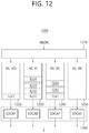
- FIG. 12 is a diagram showing a conceptual view of an inside of an STA performing an EDCA procedure in a wireless LAN system according to an exemplary embodiment of the present invention.
- an STA may perform an enhanced distributed channel access (EDCA) procedure based on a plurality of user priority levels predefined (or predetermined) for buffered traffic data.
- the buffered traffic data may correspond to a Quality of Service (QoS) frame based on a plurality of user priority levels.
- QoS Quality of Service
- AC access categories
- AC_BK background
- AC_BE best effort
- AC_VI video
- AC_VO voice
- the STA performing the EDCA procedure may map traffic data, such as medium access control (MAC) service data unit (MSDU), which reaches a medium access control (MAC) layer from a logical link control (LLC) layer, to a specific AC, as shown below in Table 1.
- MAC medium access control
- MSDU medium access control service data unit
- LLC logical link control
- Table 1 is an exemplary table showing a mapping relation between user priority levels and ACs.
- a transmission queue and a channel access parameter set may be defined for each AC.
- a plurality of user priority levels may be configured based on the channel access parameter sets, which are configured differently for each AC.
- the STA may use a channel access parameter set (e.g., arbitration interframe space (AIFS)[AC], CWmin[AC], and CWmax[AC]) according to the exemplary embodiment of the present invention instead of the legacy parameter set (e.g., DCF interframe space (DIFS), CWmin, and CWmax) according to the legacy distributed coordination function (DCF).
- a channel access parameter set e.g., arbitration interframe space (AIFS)[AC], CWmin[AC], and CWmax[AC]
- AIFS arbitration interframe space
- CWmin[AC] CWmin[AC]
- CWmax[AC] e.g., DCF interframe space (DIFS), CWmin, and CWmax
- DCF legacy distributed coordination function
- An EDCA parameter set element may function as an important means that is used for differentiating channel access of the STA, which transmits QoS traffic having different user priority levels. For example, as values of AIFS [AC] and CWmin[AC] corresponding to each AC become smaller, since the delay time for channel access becomes shorted, differentiated user priority levels may be implemented accordingly.
- the EDCA parameter set element included in the beacon frame may include a channel access parameter set (i.e., AIFS [AC], CWmin[AC], CWmax[AC]) for each AC.
- a channel access parameter set i.e., AIFS [AC], CWmin[AC], CWmax[AC]
- the channel access parameter set that is used for each AC may be set as a default value.
- a differentiated backoff procedure may be individually performed for each AC. Adequately setting up the channel access parameter set for each AC may optimize the performance and may enhance transmission performance in accordance with the priority level of the traffic at the same time.
- the user priority level that is pre-defined for the traffic data (or traffic) may be referred to as a traffic identifier (hereinafter referred to as ‘TID’).
- TID traffic identifier
- the transmission priority level of the traffic data may be determined based on the user priority level.
- the traffic ID (TID) of the traffic data having the highest user priority level may be set to ‘7’. More specifically, the traffic data having its traffic identifier set to ‘7’ may be understood as the traffic having the highest transmission priority level.
- one STA (or AP) 1200 may include a virtual mapper 1210 , a plurality of transmission queues 1220 to 1250 , and a virtual collision handler 1260 .
- the virtual mapper 1210 of FIG. 12 may map an MSDU that is received from a logical link control (LLC) layer to transmission queues corresponding to each AC in accordance with the Table 1, which is presented above.
- LLC logical link control
- the transmission queue 1220 of the AC_VO type of FIG. 12 may include one frame 1221 for a second STA (not shown).
- the transmission queue 1230 of the AC_VI type may include 3 frames 1231 to 1233 for a first STA (not shown) and one frame 1234 for a third STA (not shown) in accordance with a transmission order by which the frames are to be transmitted to a physical layer.
- the transmission queue 1240 of the AC_BE type of FIG. 12 may include one frame 1241 for a second STA (not shown), one frame 1242 for a third STA (not shown), and one frame 1243 for a second STA (not shown) in accordance with a transmission order by which the frames are to be transmitted to a physical layer.
- the transmission queue 1250 of the AC_BK type may not include a frame that is to be transmitted to a physical layer.
- the plurality of transmission queues 1220 to 1250 of FIG. 12 may operate as an individual contention entity of the EDCA procedure inside the STA in order to determine the traffic, which is to be transmitted through a wireless medium.
- the transmission queue 1220 of the AC_VO type, the transmission queue 1230 of the AC_VI type, and the transmission queue 1240 of the AC_BE type, wherein the buffered traffic exists in the transmission queues of FIG. 12 may each be understood as an individual contention entity of the EDCA procedure.
- the transmission queue 1220 of the AC_VO type, the transmission queue 1230 of the AC_VI type, and the transmission queue 1240 of the AC_BE type may each perform the EDCA procedure based on the channel access parameter set (i.e., AIFS [AC], CWmin[AC], CWmax[AC]) for each AC.
- AIFS AIFS [AC], CWmin[AC], CWmax[AC]
- a specific transmission queue that has acquired channel access through the EDCA procedure inside the STA may be referred to as a primary AC.
- the traffic included in the primary AC may be transmitted to another entity (e.g., another STA or AP) during a transmission opportunity (hereinafter referred to as ‘TXOP’).
- collision between the ACs may be adjusted (or controlled) by the virtual collision handler 1260 within the STA.
- the frame that is buffered for the AC having the higher priority level may be transmitted firsthand.
- other ACs may increase the contention window value and may update the values configured in a backoff count.
- the TXOP may be started when the STA approaches (or access) a wireless medium based on the rules of the EDCA procedure. If two or more frames are included in one AC, and when a TXOP is acquired by the STA, the STA may attempt to transmit a plurality of frames through the MAC layer.
- the STA may attempt to perform the transmission of the next frame after one SIFS time interval.
- a TXOP limit value may be set as a default value in the AP and the STA, and a frame that is related to the TXOP limit value may be transported (or delivered) to the STA from the AP. If a size of the data frame that is to be transmitted exceeds the TXOP limit value, the STA may perform fragmentation on the corresponding frame into a plurality of smaller frames. Subsequently, the fragmented frames may be transmitted within a range that does not exceed the TXOP limit value.
- a backoff procedure which generates a new backoff count of the STA may be understood based on the backoff procedure of a legacy DCF.
- each STA may individually determine a frame that is to be transmitted from each STA through an internal backoff procedure that is related to a plurality of transmission queues within the STA. Each may configure a backoff time in the backoff counter for each STA based on the individually determined frames. Each STA may perform a contention-based backoff procedure with another STA based on the backoff counter. In this case, the STA that is the first to have the backoff time in its backoff counter to be equal to ‘0’ may acquire the transmission opportunity (TXOP).
- TXOP transmission opportunity
- FIG. 13 is a conceptual diagram illustrating a backoff procedure according to an EDCA procedure according to an exemplary embodiment of the present invention.
- the traffic data (or traffic) may be transmitted in accordance with a contention-based EDCA procedure according to the corresponding user priority level.
- the priority level that is assigned to each set of traffic data may be set to any one of the 8 user priority levels indicated in Table 1.
- one STA may include 4 output queues (i.e., transmission queues). Each transmission queue may perform a channel access operation in accordance with the rules of the EDCA procedure. Each transmission queue may transmit traffic data based on differentiated Arbitration Interframe Space (AIFS) values according to the user priority levels instead of the conventionally used DCF Interframe Space (DIFS).
- AIFS differentiated Arbitration Interframe Space
- the wireless LAN system may minimize collision occurring between the STAs.
- each STA may set up a backoff time (Tb[i]) to a backoff timer.
- Tb[i] a backoff time
- the backoff time (Tb[i]) may be calculated by using Equation 1 shown below.
- T b [ i ] Random( i ) ⁇ Slot Time [Equation 1]
- Random(i) refers to a function using uniform distribution and generating a random integer between 0 and CW[i].
- CW[i] corresponds to a contention window that is selected between a minimum contention window CWmin[i] and a maximum contention window CWmax[i].
- i may indicate a user priority level of the traffic data.
- a PF value may be calculated in accordance with a procedure that is defined in the IEEE 802.11e standard.
- the CWmin[i], CWmax[i], AIFS and PF values, which are included in the channel access parameter set, may each be set as a default value in each STA (or AP).
- the channel access parameter set may be received from the AP through a QoS parameter set element, which is included in a management frame or a beacon frame.
- the device may correspond to an apparatus that is capable of supporting both the wireless LAN system and the cellular system. More specifically, the device may be interpreted as a UE supporting the cellular system or as an STA supporting the wireless LAN system.
- the backoff procedure of the EDCA procedure may be performed based on Equation 1 and Equation 2, which are presented above.
- the transmission queue 1230 of the AC_VI type may acquire a transmission opportunity (hereinafter referred to as ‘TXOP’) allowing access to the wireless medium.
- TXOP transmission opportunity
- the AP 1200 of FIG. 12 may determine the transmission queue 1230 of the AC_VI type as a primary AC and may determine the remaining transmission queues 1220 , 1240 , and 1250 as secondary ACs.
- a process of performing a backoff procedure on the plurality of transmission queues 1220 to 1250 and determining the transmission queue having its backoff procedure completed firsthand as the primary AC may be referred to as a primary AC rule.
- a transmission opportunity section for the transmission opportunities may be determined based on the primary AC, which is determined in accordance with the above-described primary AC rule. Additionally, frames that are included in secondary ACs may also be transmitted in the transmission opportunity section, which is determined based on the primary AC.
- the EDCA procedure of a user STA may be activated or deactivated. For example, whether or not the EDCA procedure is activated may be determined during an association step or a negotiation step. Alternatively, after determining whether or not the EDCA procedure is activated, the determined result may be signaled to the AP through a separate frame (e.g., OMI frame).
- a separate frame e.g., OMI frame
- FIG. 14 is a diagram for describing a backoff cycle and a frame transmission procedure in a wireless LAN system of this specification.
- a horizontal axis t 1 to t 5 for each of first to fifth STAs 1410 to 1450 may represent a time axis.
- a vertical axis for each of the first to fifth STAs 1410 to 1450 may represent a backoff time that is being transmitted.
- the plurality of STAs may attempt to transmit data (or frames).
- each STA may select a backoff time (Tb[i]) according to Equation 1 and may, then, attempt to perform transmission after standing-by (or waiting) for as long as slot times corresponding to the selected backoff time (Tb[i]).
- each STA may perform countdown of the selected backoff count time in slot time units.
- Each STA may continuously monitor the medium while performing the countdown. While monitoring the medium, if the medium is determined to be in an Occupied state, the STA may suspend the countdown and be on stand-by. While monitoring the medium, if the medium is determined to be in an Idle state, the STA may resume the countdown.
- the third STA 1430 may verify whether or not the medium is in an Idle state during a DIFS. Subsequently, if it is determined that the medium is in an Idle state during a DIFS, the third STA 1430 may transmit a frame to an AP (not shown).
- an inter frame space (IFS) of FIG. 14 is illustrated as a DIFS, it shall be understood that this specification will not be limited only to this.
- each of the remaining STAs may verify the Occupied state of the medium and may then be on stand-by during the transmission period of the frame.
- the frame may reach MAC layers corresponding to each of the first STA 1410 , the second STA 1420 , and the fifth STA 1450 .
- each STA may be on stand-by for as long as on DIFS and may, then, perform countdown of a backoff time, which is individually selected by each STA.
- the drawing shows an example, wherein the second STA 1420 selects a shortest backoff time (or a smallest backoff time value), and wherein the first STA 1410 selects a longest backoff time (or a largest backoff time value).
- T 1 transmission start point for transmitting a frame
- FIG. 14 shows an example, wherein the remaining backoff time of the fifth STA 1450 is shorter than the remaining backoff time of the first STA 1410 .
- the first STA 1410 and the fifth STA 1450 may suspend their backoff procedures and may be on stand-by. Thereafter, when the medium occupation of the second STA 1420 is completed (or ended) (i.e., if the medium returns to the Idle state), the first STA 1410 and the fifth STA 1450 may be on stand-by for as long as a DIFS.
- the first STA 1410 and the fifth STA 1450 may resume their backoff procedures, which were suspended earlier, based on the remaining backoff time.
- the fifth STA 1450 may complete its backoff procedure earlier than the first STA 1410 .
- a frame for the fourth STA 1440 may reach a MAC layer of the fourth STA 1440 .
- the fourth STA 1440 may be on stand-by for as long as a DIFS. Thereafter, the fourth STA 1440 may perform countdown of a backoff time, which is selected by the fourth STA 1440 .
- the remaining backoff time of the fifth STA 1450 may coincidently be identical to the backoff time of the fourth STA 1440 .
- collision may occur between the fourth STA 1440 and the fifth STA 1450 .
- both the fourth STA 1440 and the fifth STA 1450 may become incapable of receiving ACKs and may also fail to perform data transmission.
- the fourth STA 1440 and the fifth STA 1450 may individually calculate a new contention window (CW new [i]) according to Equation 2, which is presented above. Subsequently, the fourth STA 1440 and the fifth STA 1450 may individually perform countdown of the backoff time, which is newly calculated in accordance with Equation 2.
- the first STA 1410 may be on stand-by. Subsequently, when the medium returns to the Idle state, the first STA 1410 may be on stand-by for as long as a DIFS and may, then, resume the backoff counting. When the remaining backoff time of the first STA 1410 is elapsed, the first STA 1410 may transmit a frame.
- a CSMA/CA mechanism may also include virtual carrier sensing in addition to physical carrier sensing, wherein the AP and/or STA directly senses the medium.
- Virtual carrier sensing is performed to compensate problems that may occur during medium access, such as a hidden node problem, and so on.
- a MAC of the WLAN system uses a Network Allocation Vector (NAV).
- NAV Network Allocation Vector
- the NAV corresponds to a value that is indicated by an AP and/or an STA that is currently using the medium or that has the authority to use the medium to another AP and/or STA, wherein the value indicates the time remaining until the medium returns to its state of being available for usage.
- a value that is set as the NAV corresponds to a time period during which the usage of the medium is scheduled by the AP and/or STA, which transmits the corresponding frame, and the STA receiving the NAV value is prohibited from accessing the medium during the corresponding time period.
- FIG. 15 is a diagram illustrating a method for transmitting a frame in a wireless LAN system that is performed by a wireless device according to an exemplary embodiment of the present invention.
- a horizontal axis of an AP 1510 shown in FIG. 15 represents time (t 1 ), and a vertical axis may be associated with the existence (or presence) of a frame that is being transmitted from the AP 1510 .
- a horizontal axis of an STA 1520 shown in FIG. 15 represents time (t 2 ), and a vertical axis may be associated with the existence (or presence) of a frame that is being transmitted from the STA 1520 .
- the STA 1520 may be understood as a receiving device of a trigger frame, having a plurality of resource units for the uplink transmission performed by a plurality of user STAs individually allocated thereto.
- the STA 1520 may maintain two parameters (used_time, admitted_time) for each AC (AC_VO, AC_VI, AC_BE, AC_BK) shown in FIG. 12 .
- the STA 1520 may maintain a plurality of first time parameters corresponding to the admitted time (admitted_time) for each AC (AC VO, AC VI, ACBE, AC BK) and a plurality of second time parameters corresponding to the used time (used_time) for each AC (AC VO, AC VI, AC BE, AC BK).
- the plurality of first time parameters may be understood as a concept including a first time parameter for the admitted_time of AC_VO, a first time parameter for the admitted_time of AC_VI, a first time parameter for the admitted_time of AC_BE, and a first time parameter for the admitted_time of AC_BK.
- the plurality of second time parameters may be understood as a concept including a second time parameter for the used_time of AC_VO, a second time parameter for the used_time of AC_VI, a second time parameter for the used_time of AC_BE, and a second time parameter for the used_time of AC_BK.
- the STA 1520 of FIG. 15 may compare the first time parameter for an AC of a corresponding frame with the second time parameter for the AC of the corresponding frame.
- the plurality of first time parameters related to the admitted_time and the plurality of second time parameters related to the used_time may be set to initial values (e.g., ‘0’) during an association (or re-association) step between the user STA and the AP.
- a value that is set as an admitted_time′ may indicate an admitted time, which was previously admitted (until the current time) by the AP for the user STA for each AC.
- a value corresponding to 11EDCAAveragingPeriod and a value corresponding to a medium time of TSPEC may correspond to values that are set in a session forming step based on an add traffic stream (ADDTS) response frame, which is received from the AP.
- ADDTS add traffic stream
- the add traffic stream (ADDTS) response frame may correspond to a frame that is received as a response to an ADDTS request frame, which is transmitted by the user STA for the session formation of the user STA.
- ADDTS add traffic stream
- a traffic specification (TSPEC) element may be included in an add traffic stream (ADDTS) response frame.
- a value corresponding to a medium time of the TSPEC may be set up for each AC based on the traffic specification (TSPEC) element.
- the plurality of second time parameters related to the used_time may indicate the time that is used for the transmission performed by the user STA.
- the plurality of second time parameters related to the used_time may be calculated based on Equation 4 shown below.
- used_time used_time′+MPDUExchangeTime [Equation 4]
- a value that is set as a used_time′ may indicate a used time, which was previously used (until the current time) by the user STA for each AC.
- a value that is set as MPDUExchangeTime may be understood as a summed value of a first processing time that is required for the transmission of a frame corresponding to a specific AC that is currently scheduled to be transmitted, a second processing time that is required for the reception of an acknowledgement frame for a frame corresponding to a specific AC that is currently scheduled to be transmitted, and a time corresponding to a SIFS.
- the user STA may update the second time parameter corresponding to the used_time of the specific AC.
- the STA 1520 may compare the first time parameter related to the admitted_time of the specific AC with the second time parameter related to the used_time of the specific AC.
- the STA 1520 may transmit a frame related to the specific AC through/based on the EDCA to the AP 1510 .
- the STA 1520 may not transmit a frame related to the specific AC.
- the STA 1520 Even if the STA 1520 according to the exemplary embodiment of the present invention acquires a transmission opportunity (TXOP) for transmitting a frame included in the specific AC through/based on the EDCA, if the second time parameter of the specific AC exceeds the first time parameter of the specific AC, the STA 1520 may withdraw (or abandon) the transmission of the frame included in the specific AC for which it has acquired the transmission opportunity (TXOP).
- TXOP transmission opportunity
- the STA 1520 may be understood as a wireless device that has acquired a transmission opportunity (TXOP) for a specific AC (e.g., AC_VO) through/based on a contention-based EDCA procedure with another STA (not shown) and the AP 1510 .
- TXOP transmission opportunity
- a first uplink frame (UL #1) of FIG. 15 may be understood as a frame included in AC_VO shown in FIG. 12 .
- the STA 1520 may compare a second time parameter that is maintained for a specific AC (i.e., AC_VO) with a first time parameter related to an admitted_time that is predetermined for a specific AC (i.e., AC_VO). Then, the STA 1520 may determine whether or not to transmit the first uplink frame (UL #1).
- the STA 1520 of FIG. 15 may transmit a first uplink frame (UL #1) to the AP 1510 through/based on the EDCA.
- the first uplink frame (UL #1) may correspond to a QoS data frame or a QoS Null frame.
- a second period T 2 to T 3 may be understood as a period being request for the reception of an acknowledgement frame (ACK #1) related to the first uplink frame (UL #1).
- a third period T 3 to T 4 may correspond to a SIFS.
- a second time parameter related to the used time of a specific AC may be newly calculated based on Equation 4, which is presented above.
- a second time parameter of the specific AC i.e., AC_VO may be newly calculated.
- a value of the MPDUExchangeTime related to the first uplink frame (UL #1) may be set as a summed value of a first processing time (i.e., T 1 to T 2 of FIG. 15 ) being required for the transmission of the first uplink frame (UL #1), a second processing time (i.e., T 2 to T 3 of FIG. 15 ) being required for the reception of the acknowledgement frame (ACK #1), and a SIFS (i.e., T 3 to T 4 of FIG. 15 ).
- a first processing time i.e., T 1 to T 2 of FIG. 15
- a second processing time i.e., T 2 to T 3 of FIG. 15
- SIFS i.e., T 3 to T 4 of FIG. 15
- the AP 1510 and the 1520 may be on stand-by.
- the STA 1520 may receive a trigger frame (TF) for a Multi-User Uplink transmission from the AP 1510 .
- TF trigger frame
- an uplink Resource Unit for the STA 1520 may be included in the trigger frame (TF).
- a sixth period T 6 to T 7 may correspond to a SIFS.
- the STA 1520 may transmit a trigger-based uplink frame (UL #2) to the AP 1510 as a response to the trigger frame (TF).
- the trigger-based uplink frame (UL #2) may be understood as a frame included in the above-described AC_VO shown in FIG. 12 .
- a second time parameter related to the used_time of the specific AC i.e., AC_VO
- AC_VO the used_time of the specific AC
- the STA 1520 may not sum (or add) the previously used time (used_time′) of the specific AC (i.e., AC_VO) and the MPDUExchangeTime related to the trigger-based uplink frame (UL #2).
- the MPDUExchangeTime of Equation 4 may not be considered.
- the trigger-based uplink frame (UL #2) may be transmitted regardless of a comparison result between a value of a second time parameter related to the previously used time (used_time′) of the specific AC (i.e., AC_VO) and a value of a first time parameter related to the admitted_time of the specific AC (i.e., AC_VO) (i.e., even if the second time parameter exceeds the first time parameter).
- An eighth period T 8 to T 9 may correspond to a SIFS.
- the STA 1520 may receive an acknowledgement frame (ACK #2) for notifying the successful reception of the trigger-based uplink frame (UL #2) from the AP 1510 .
- ACK #2 acknowledgement frame
- the period related to the MPDUExchangeTime of Equation 4 may be understood as the seventh period T 7 to T 8 to the ninth period T 9 to T 10 .
- the value related to the seventh period T 7 to T 8 to the ninth period T 9 to T 10 i.e., MPDUExchangeTime
- used_time′ the previously used time of the specific AC (i.e., AC_VO) in accordance with Equation 4.
- the value related to the seventh period T 7 to T 8 to the ninth period T 9 to T 10 is merely exemplary. And, therefore, it should be understood that the present invention will not be limited only to this.
- the MPDUExchangeTime of Equation 4 may indicate a time corresponding to a period that is related to the transmission of the trigger-based uplink frame (UL #2).
- a value corresponding to a summed value of the seventh period T 7 to T 8 to the ninth period T 9 to T 10 and the SIFS may be set as the MPDUExchangeTime of Equation 4.
- acknowledgement frame (ACK #2) of FIG. 15 may correspond to a frame being transmitted to a plurality of STAs for notifying successful reception of a plurality of uplink frames being respectively transmitted from the plurality of STAs.
- the AP 1510 and the 1520 may be on stand-by.
- the STA 1520 may be understood as a wireless device that has acquired a transmission opportunity (TXOP) for a specific AC (e.g., AC_VO) through/based on a contention-based EDCA procedure with another STA (not shown) and the AP 1510 .
- TXOP transmission opportunity
- AC_VO transmission opportunity
- a third uplink frame (UL #3) of FIG. 15 may be understood as a frame included in AC_VO shown in FIG. 12 .
- the STA 1520 may compare a second time parameter of the specific AC (i.e., AC_VO), which is newly calculated during the process of transmitting the first uplink frame (UL #1), with a first time parameter corresponding to the admitted_time of the specific AC (i.e., AC_VO), and the STA 1520 may, then, determine whether or not to transmit a third uplink frame (UL #3).
- AC_VO the specific AC
- FIG. 16 is a flow chart illustrating a method for transmitting a frame in a wireless LAN system that is performed by a wireless device according to an exemplary embodiment of the present invention.
- the user STA may determine whether or not a frame that is to be transmitted corresponds to a frame that is to be transmitted through/based on the EDCA.
- step S 1610 when it is determined that the frame that is to be transmitted by the user STA does not correspond to a frame that is to be transmitted through/based on the EDCA, step S 1620 may be performed.
- the frame that is to be transmitted may be understood as a trigger-based frame, which corresponds to a response to a trigger frame for a multi-user uplink (MU UL) transmission, which is received from the AP.
- MU UL multi-user uplink
- step S 1620 when a trigger-based frame is transmitted, the user STA may not add (or sum) a required time for the trigger-based frame to the second time parameter which indicates an amount of the previously used time (used_time′) having been used for transmission of frames related to the specific AC, in accordance with Equation 4.
- the second time parameter related to the used time (used_time) of the specific AC is not updated, and the user STA may maintain the value related to the previously used time (used_time′) of the specific AC as the second time parameter.
- the user STA may compare the first time parameter related to the admitted_time of the specific AC with the second time parameter related to the used_time of specific AC. And, then, regardless of the comparison result (i.e., even if the second time parameter of the specific AC exceeds the first time parameter of the specific AC), the user STA may transmit a trigger-based frame as a response to the received trigger frame.
- step S 1610 when it is determined that the frame that is to be transmitted by the user STA corresponds to a frame that is to be transmitted based on the EDCA, step S 1630 may be performed.
- the user STA may compare a first time parameter related to the admitted time of the specific AC of a frame that is to be transmitted through/based on the EDCA with a second time parameter related to the used time of the specific AC.
- the user STA may be understood as a wireless device that has acquired a transmission opportunity (TXOP) for a specific AC through/based on a contention-based EDCA procedure with another STA and the AP.
- TXOP transmission opportunity
- step S 1630 if the second time parameter, which has been maintained as a previous value for the specific AC, does not exceed the first time parameter for the specific AC, step S 1640 may be performed.
- step S 1640 the user STA may transmit a frame of the specific AC to the AP through/based on the EDCA.
- the user STA may newly calculate (or update) the second time parameter related to the used_time of the specific AC.
- the required time for the frame of the specific AC, which is transmitted through/based on the EDCA may correspond to a summed value of a first processing time being required for the transmission of a sequence included in the frame that is to be transmitted through/based on the EDCA, a second processing time being required for the reception of an acknowledgement frame for the frame that is to be transmitted through/based on the EDCA, and a time corresponding to Short-Inter Frame Spacing (SIFS).
- SIFS Short-Inter Frame Spacing
- step S 1650 may be performed.
- the user STA cannot transmit the corresponding frame through/based on the EDCA.
- the process that is performed based on the EDCA and the process that is performed based on the trigger frame may be considered and understood as processes each being independent from one another.
- the wireless LAN system when performing transmission of a trigger frame, due to an influence caused by the process being performed based on the EDCA, failure in the transmission of a trigger-based frame may be reduced.
- a wireless LAN system having an enhanced performance may be provided.
- FIG. 17 is a block view illustrating a wireless device to which the exemplary embodiment of the present invention can be applied.
- the wireless device may correspond to an AP or a non-AP station (STA).
- the wireless device may correspond to the above-described user or may correspond to a transmitting device transmitting a signal to the user.
- the AP 1700 includes a processor 1710 , a memory 1720 , and a radio frequency (RF) unit 1730 .
- RF radio frequency
- the RF unit 1730 is connected to the processor 1710 , thereby being capable of transmitting and/or receiving radio signals.
- the processor 1710 implements the functions, processes, and/or methods proposed in the present invention.
- the processor 1710 may be implemented to perform the operations according to the above-described exemplary embodiments of the present invention. More specifically, among the operations that are disclosed in the exemplary embodiments of FIG. 1 to FIG. 16 , the processor 1710 may perform the operations that may be performed by the AP.
- the non-AP STA 1750 includes a processor 1760 , a memory 1770 , and a radio frequency (RF) unit 1780 .
- RF radio frequency
- the RF unit 1780 is connected to the processor 1760 , thereby being capable of transmitting and/or receiving radio signals.
- the processor 1760 implements the functions, processes, and/or methods proposed in the present invention.
- the processor 1760 may be implemented to perform the operations of the non-AP STA according to the above-described exemplary embodiments of the present invention.
- the processor may perform the operations of the non-AP STA, which are disclosed in the exemplary embodiments of FIG. 1 to FIG. 16 .
- the processor 1710 and 1760 may include an application-specific integrated circuit (ASIC), another chip set, a logical circuit, a data processing device, and/or a converter converting a baseband signal and a radio signal to and from one another.
- the memory 1720 and 1770 may include a read-only memory (ROM), a random access memory (RAM), a flash memory, a memory card, a storage medium, and/or another storage device.
- the RF unit 1730 and 1780 may include one or more antennas transmitting and/or receiving radio signals.
- the above-described method may be implemented as a module (process, function, and so on) performing the above-described functions.
- the module may be stored in the memory 1720 and 1770 and may be executed by the processor 1710 and 1760 .
- the memory 1720 and 1770 may be located inside or outside of the processor 1710 and 1760 and may be connected to the processor 1710 and 1760 through a diversity of well-known means.
- a method of transmitting a frame in a wireless LAN system having a more enhanced performance and a wireless device using the same may be provided.
Landscapes
- Engineering & Computer Science (AREA)
- Computer Networks & Wireless Communication (AREA)
- Signal Processing (AREA)
- Quality & Reliability (AREA)
- Mobile Radio Communication Systems (AREA)
Abstract
Description
| TABLE 1 | ||||
| Priority level | User priority level | Access Category (AC) | ||
| Low | 1 | |
||
| 2 | AC_BK | |||
| 0 | |
|||
| 3 | |
|||
| 4 | |
|||
| 5 | |
|||
| 6 | AC_VO | |||
| High | 7 | AC_VO | ||
T b[i]=Random(i)×Slot Time [Equation 1]
CW new[i]=((CW old[i]+1)×PF)−1 [Equation 2]
admitted_time=admitted_time′+11EDCAAveragingPeriod×mediumtime of TSPEC [Equation 3]
used_time=used_time′+MPDUExchangeTime [Equation 4]
Claims (10)
Priority Applications (1)
| Application Number | Priority Date | Filing Date | Title |
|---|---|---|---|
| US16/321,820 US10595288B2 (en) | 2016-08-21 | 2017-05-17 | Method for transmitting frame in wireless LAN system and wireless terminal using same |
Applications Claiming Priority (3)
| Application Number | Priority Date | Filing Date | Title |
|---|---|---|---|
| US201662377663P | 2016-08-21 | 2016-08-21 | |
| PCT/KR2017/005104 WO2018038354A1 (en) | 2016-08-21 | 2017-05-17 | Method for transmitting frame in wireless lan system and wireless terminal using same |
| US16/321,820 US10595288B2 (en) | 2016-08-21 | 2017-05-17 | Method for transmitting frame in wireless LAN system and wireless terminal using same |
Publications (2)
| Publication Number | Publication Date |
|---|---|
| US20190174442A1 US20190174442A1 (en) | 2019-06-06 |
| US10595288B2 true US10595288B2 (en) | 2020-03-17 |
Family
ID=61246357
Family Applications (1)
| Application Number | Title | Priority Date | Filing Date |
|---|---|---|---|
| US16/321,820 Active US10595288B2 (en) | 2016-08-21 | 2017-05-17 | Method for transmitting frame in wireless LAN system and wireless terminal using same |
Country Status (4)
| Country | Link |
|---|---|
| US (1) | US10595288B2 (en) |
| EP (1) | EP3503661B1 (en) |
| KR (1) | KR102085872B1 (en) |
| WO (1) | WO2018038354A1 (en) |
Cited By (1)
| Publication number | Priority date | Publication date | Assignee | Title |
|---|---|---|---|---|
| US12382340B2 (en) | 2014-09-17 | 2025-08-05 | Wilus Institut Of Standards And Technology Inc. | Wireless communication method using frame aggregation and wireless communication terminal using same |
Families Citing this family (1)
| Publication number | Priority date | Publication date | Assignee | Title |
|---|---|---|---|---|
| US12167410B2 (en) | 2019-07-05 | 2024-12-10 | Lg Electronics Inc. | Method and device for receiving PPDU having been subjected to LDPC tone mapping in broadband tone plan in wireless LAN system |
Citations (13)
| Publication number | Priority date | Publication date | Assignee | Title |
|---|---|---|---|---|
| US20050138451A1 (en) * | 2003-12-19 | 2005-06-23 | Simpson Floyd D. | Uplink poll-based power save delivery method in a wireless local area network for real time communication |
| US20050136833A1 (en) * | 2003-12-19 | 2005-06-23 | Emeott Stephen P. | Unscheduled power save delivery method in a wireless local area network for real time communication |
| US20060045051A1 (en) * | 2004-08-30 | 2006-03-02 | Andreas Floros | Method and system for a quality of service mechanism for a wireless network |
| US20060215686A1 (en) * | 2005-03-28 | 2006-09-28 | Nokia Corporation | Communication method for accessing wireless medium under enhanced distributed channel access |
| US7123627B2 (en) * | 2001-09-11 | 2006-10-17 | Sharp Laboratories Of America, Inc. | Class of computationally parsimonious schedulers for enforcing quality of service over packet based AV-centric home networks |
| US20080101320A1 (en) * | 2006-11-01 | 2008-05-01 | Spectralink | Method for actively synchronizing U-APSD service periods |
| US20090168717A1 (en) * | 2004-01-08 | 2009-07-02 | Interdigital Technology Corporation | Wireless local area network radio resource management admission control |
| US20110051647A1 (en) * | 2009-08-25 | 2011-03-03 | Qualcomm Incorporated | Method and apparatus for multiple-user communication in a client initiated communication transmission scheme |
| US20110141968A1 (en) * | 2009-12-15 | 2011-06-16 | Solomon Trainin | Techniques for managing heterogeneous traffic streams |
| US20140301383A1 (en) * | 2011-10-17 | 2014-10-09 | Korea University Research And Business Foundation | Method and apapratus for transmitting a frame in a wireless lan system |
| KR20160090360A (en) | 2013-11-26 | 2016-07-29 | 마벨 월드 트레이드 리미티드 | Uplink multi-user multiple input multiple output for wireless local area network |
| US20170318501A1 (en) * | 2014-11-04 | 2017-11-02 | Telefonaktiebolaget Lm Ericsson (Publ) | Methods and apparatus for integration of wireless wide area networks with wireless local area networks |
| US20180199375A1 (en) * | 2015-07-08 | 2018-07-12 | Canon Kabushiki Kaisha | Improved contention mechanism for access to random resource units in an 802.11 channel |
Family Cites Families (4)
| Publication number | Priority date | Publication date | Assignee | Title |
|---|---|---|---|---|
| US7801043B2 (en) * | 2005-04-01 | 2010-09-21 | Interdigital Technology Corporation | Method and apparatus for admission control and resource tracking in a wireless communication system |
| KR102548620B1 (en) * | 2014-10-01 | 2023-06-29 | 엘지전자 주식회사 | Method for transmitting data in a wireless communication system and apparatus therefor |
| US9942925B2 (en) * | 2015-01-07 | 2018-04-10 | Qualcomm, Incorporated | Station contention behavior in uplink multiple user protocols |
| US10257854B2 (en) * | 2015-02-02 | 2019-04-09 | Samsung Electronics Co., Ltd. | Management of uplink multi-user transmissions in wireless local area networks |
-
2017
- 2017-05-17 US US16/321,820 patent/US10595288B2/en active Active
- 2017-05-17 EP EP17843774.5A patent/EP3503661B1/en active Active
- 2017-05-17 KR KR1020197004945A patent/KR102085872B1/en active Active
- 2017-05-17 WO PCT/KR2017/005104 patent/WO2018038354A1/en not_active Ceased
Patent Citations (13)
| Publication number | Priority date | Publication date | Assignee | Title |
|---|---|---|---|---|
| US7123627B2 (en) * | 2001-09-11 | 2006-10-17 | Sharp Laboratories Of America, Inc. | Class of computationally parsimonious schedulers for enforcing quality of service over packet based AV-centric home networks |
| US20050136833A1 (en) * | 2003-12-19 | 2005-06-23 | Emeott Stephen P. | Unscheduled power save delivery method in a wireless local area network for real time communication |
| US20050138451A1 (en) * | 2003-12-19 | 2005-06-23 | Simpson Floyd D. | Uplink poll-based power save delivery method in a wireless local area network for real time communication |
| US20090168717A1 (en) * | 2004-01-08 | 2009-07-02 | Interdigital Technology Corporation | Wireless local area network radio resource management admission control |
| US20060045051A1 (en) * | 2004-08-30 | 2006-03-02 | Andreas Floros | Method and system for a quality of service mechanism for a wireless network |
| US20060215686A1 (en) * | 2005-03-28 | 2006-09-28 | Nokia Corporation | Communication method for accessing wireless medium under enhanced distributed channel access |
| US20080101320A1 (en) * | 2006-11-01 | 2008-05-01 | Spectralink | Method for actively synchronizing U-APSD service periods |
| US20110051647A1 (en) * | 2009-08-25 | 2011-03-03 | Qualcomm Incorporated | Method and apparatus for multiple-user communication in a client initiated communication transmission scheme |
| US20110141968A1 (en) * | 2009-12-15 | 2011-06-16 | Solomon Trainin | Techniques for managing heterogeneous traffic streams |
| US20140301383A1 (en) * | 2011-10-17 | 2014-10-09 | Korea University Research And Business Foundation | Method and apapratus for transmitting a frame in a wireless lan system |
| KR20160090360A (en) | 2013-11-26 | 2016-07-29 | 마벨 월드 트레이드 리미티드 | Uplink multi-user multiple input multiple output for wireless local area network |
| US20170318501A1 (en) * | 2014-11-04 | 2017-11-02 | Telefonaktiebolaget Lm Ericsson (Publ) | Methods and apparatus for integration of wireless wide area networks with wireless local area networks |
| US20180199375A1 (en) * | 2015-07-08 | 2018-07-12 | Canon Kabushiki Kaisha | Improved contention mechanism for access to random resource units in an 802.11 channel |
Non-Patent Citations (8)
Cited By (1)
| Publication number | Priority date | Publication date | Assignee | Title |
|---|---|---|---|---|
| US12382340B2 (en) | 2014-09-17 | 2025-08-05 | Wilus Institut Of Standards And Technology Inc. | Wireless communication method using frame aggregation and wireless communication terminal using same |
Also Published As
| Publication number | Publication date |
|---|---|
| EP3503661B1 (en) | 2021-10-27 |
| US20190174442A1 (en) | 2019-06-06 |
| KR102085872B1 (en) | 2020-03-06 |
| KR20190028795A (en) | 2019-03-19 |
| EP3503661A1 (en) | 2019-06-26 |
| EP3503661A4 (en) | 2020-07-22 |
| WO2018038354A1 (en) | 2018-03-01 |
Similar Documents
| Publication | Publication Date | Title |
|---|---|---|
| US10743316B2 (en) | Method and apparatus for performing uplink transmission in wireless LAN system | |
| US10667281B2 (en) | Method for transmitting uplink frame in wireless LAN system and wireless device using the same | |
| US10735151B2 (en) | Method for transmitting uplink frame in wireless local area network and wireless device using the same | |
| US10624106B2 (en) | Method for transmitting uplink frames of multiple users in a wireless LAN system | |
| US10455557B2 (en) | Method of supporting for uplink multi-user transmission in wireless area network system | |
| US10575314B2 (en) | Method for transmitting trigger frame in wireless LAN system and terminal using same | |
| US10764921B2 (en) | Method for frame transmitted on basis of random access in wireless LAN system and wireless terminal using same | |
| US10206230B2 (en) | Method for transmitting frame in wireless local area network and wireless terminal using the same | |
| US11178568B2 (en) | Method for uplink transmission in wireless LAN system and wireless terminal using same | |
| US10440649B2 (en) | Method for performing power management in wireless LAN system and wireless device using the same | |
| US9900871B1 (en) | Method for transmitting uplink frame in wireless LAN system and wireless device using the same | |
| US10251199B2 (en) | Method for transmitting frame in wireless local area network and wireless device using the same | |
| US20190075583A1 (en) | Method for uplink transmission, and wireless terminal using method in wireless lan system | |
| US10225843B2 (en) | Method and apparatus for changing operating mode in wireless local area network system | |
| US10455556B2 (en) | Method and apparatus for changing operating mode in wireless local area network system | |
| US10743369B2 (en) | Method and apparatus for changing operating mode in wireless LAN system | |
| US11190972B2 (en) | Method for performing uplink transmission in wireless LAN system and terminal using same | |
| US10667302B2 (en) | Method for transmitting uplink frame in wireless LAN system, and wireless terminal using same | |
| US10595288B2 (en) | Method for transmitting frame in wireless LAN system and wireless terminal using same |
Legal Events
| Date | Code | Title | Description |
|---|---|---|---|
| AS | Assignment |
Owner name: LG ELECTRONICS INC., KOREA, REPUBLIC OF Free format text: ASSIGNMENT OF ASSIGNORS INTEREST;ASSIGNORS:RYU, KISEON;KIM, JEONGKI;PARK, HYUNHEE;AND OTHERS;SIGNING DATES FROM 20190109 TO 20190114;REEL/FRAME:048181/0014 |
|
| FEPP | Fee payment procedure |
Free format text: ENTITY STATUS SET TO UNDISCOUNTED (ORIGINAL EVENT CODE: BIG.); ENTITY STATUS OF PATENT OWNER: LARGE ENTITY |
|
| STPP | Information on status: patent application and granting procedure in general |
Free format text: NON FINAL ACTION MAILED |
|
| STPP | Information on status: patent application and granting procedure in general |
Free format text: RESPONSE TO NON-FINAL OFFICE ACTION ENTERED AND FORWARDED TO EXAMINER |
|
| STPP | Information on status: patent application and granting procedure in general |
Free format text: NOTICE OF ALLOWANCE MAILED -- APPLICATION RECEIVED IN OFFICE OF PUBLICATIONS |
|
| STPP | Information on status: patent application and granting procedure in general |
Free format text: PUBLICATIONS -- ISSUE FEE PAYMENT RECEIVED |
|
| STPP | Information on status: patent application and granting procedure in general |
Free format text: PUBLICATIONS -- ISSUE FEE PAYMENT VERIFIED |
|
| STCF | Information on status: patent grant |
Free format text: PATENTED CASE |
|
| MAFP | Maintenance fee payment |
Free format text: PAYMENT OF MAINTENANCE FEE, 4TH YEAR, LARGE ENTITY (ORIGINAL EVENT CODE: M1551); ENTITY STATUS OF PATENT OWNER: LARGE ENTITY Year of fee payment: 4 |