US10594925B2 - Camera zoom level and image frame capture control - Google Patents
Camera zoom level and image frame capture control Download PDFInfo
- Publication number
- US10594925B2 US10594925B2 US15/830,851 US201715830851A US10594925B2 US 10594925 B2 US10594925 B2 US 10594925B2 US 201715830851 A US201715830851 A US 201715830851A US 10594925 B2 US10594925 B2 US 10594925B2
- Authority
- US
- United States
- Prior art keywords
- input
- touch
- region
- sensitive display
- user input
- Prior art date
- Legal status (The legal status is an assumption and is not a legal conclusion. Google has not performed a legal analysis and makes no representation as to the accuracy of the status listed.)
- Active, expires
Links
Images


Classifications
-
- H—ELECTRICITY
- H04—ELECTRIC COMMUNICATION TECHNIQUE
- H04N—PICTORIAL COMMUNICATION, e.g. TELEVISION
- H04N23/00—Cameras or camera modules comprising electronic image sensors; Control thereof
- H04N23/60—Control of cameras or camera modules
- H04N23/62—Control of parameters via user interfaces
-
- H04N5/23216—
-
- H—ELECTRICITY
- H04—ELECTRIC COMMUNICATION TECHNIQUE
- H04N—PICTORIAL COMMUNICATION, e.g. TELEVISION
- H04N23/00—Cameras or camera modules comprising electronic image sensors; Control thereof
- H04N23/60—Control of cameras or camera modules
- H04N23/63—Control of cameras or camera modules by using electronic viewfinders
-
- H—ELECTRICITY
- H04—ELECTRIC COMMUNICATION TECHNIQUE
- H04N—PICTORIAL COMMUNICATION, e.g. TELEVISION
- H04N23/00—Cameras or camera modules comprising electronic image sensors; Control thereof
- H04N23/60—Control of cameras or camera modules
- H04N23/69—Control of means for changing angle of the field of view, e.g. optical zoom objectives or electronic zooming
-
- H04N5/23293—
-
- H04N5/23296—
Definitions
- aspects of this disclosure relate generally to electronic image capture devices. More specifically, some aspects of this disclosure relate to controlling imaging operations in electronic image capture devices.
- An electronic device may include, or have access to image data received from, one or more camera modules.
- an imaging operation such as a zoom level adjustment of the one or more camera modules may be controlled.
- a zoom level adjustment of a camera module can be increased (e.g., a “zoom-in” operation) to increase an overall size of a subject relative to an image frame.
- a zoom level of the camera module can be decreased (e.g., a “zoom-out” operation) to decrease an overall size of a subject relative to an image frame and/or to capture more portions of a scene within the image frame.
- other imaging operations can be controlled.
- a device includes a memory and a processor.
- the processor is coupled to the memory.
- the processor is also coupled to a camera module and a user input surface.
- the processor is configured to receive, from the user input surface, a continuous user input.
- the user input includes a first portion and a second portion.
- the processor is also configured to control a first imaging operation based on a first input type received during the first portion.
- the first input type includes movement of an input element relative to the user input surface.
- the processor is also configured to control a second imaging operation based on a second input type received during the second portion.
- the second imaging operation is of a different type of imaging operation than the first imaging operation.
- the device can also include the camera module and a touch-sensitive display including the user input surface.
- the processor can be configured to cause the touch-sensitive display to display a preview stream received from the camera module during the first portion of the continuous user input.
- the first imaging operation can include, for example, a zoom level adjustment operation and the second imaging operation can include an image frame capture operation.
- the zoom level adjustment operation can include a digital zoom operation, an optical zoom operation, and/or a combined digital and optical zoom operation.
- the zoom level adjustment operation can include transitions between two or more cameras associated with the device.
- the processor can be configured to cause the touch-sensitive display to display a graphical user interface element.
- the processor can be configured to cause the touch-sensitive display to display the graphical user interface element in response to the initiation of the continuous user input. Further, a location of the graphical user interface element relative to the user input surface can be based on a location of the continuous user input.
- the graphical user interface element in some examples, can include a first region and a second region.
- the first input type can include movement of the input element along the user input surface over at least a portion of the first region
- the second input type can include a movement of the input element along the user input surface between the first region and the second region.
- the movement of the input element during the first portion along the user input surface can cause the second region to move relative to the first region during the first portion of the continuous user input, and the movement of the second region during the first portion can track a location of the input element relative to the user input surface as the input element moves relative to the first region.
- the first input type can include a twist of the input element relative to the user input surface and/or a translation of the input element relative to the user input surface.
- the second input type can include, for example, a release of the input element from the user input surface and/or a translation of the input element relative to the user input surface.
- the input element can include a first structure that translates relative to the user input surface and a second structure that translates relative to the user input surface during the first portion.
- the first structure and the second structure can be spaced apart from each other on a plane that is parallel to the user input surface, and the second input type can include a translation of the first structure relative to the user input surface while the second structure is stationary relative to the user input surface during the first portion.
- the second input type can include a release of at least one of the first structure and the second structure from the user input surface.
- the processor can be coupled to a second camera module that faces a different direction than the camera module.
- the processor can be configured to receive, from the user input surface, a second continuous user input.
- the second continuous user input can include a first portion and a second portion.
- the processor can also be configured to control a first imaging operation associated with the second camera module based on a first type of input received during the first portion of the second continuous user input.
- the first input type can include movement of the input element relative to the user interface surface.
- the processor can control a second imaging operation associated with the second camera module based on a second input type received during the second portion of the second continuous user input.
- the second imaging operation associated with the second camera module can be different than the first imaging operation associated with the second camera module.
- the first input type received during the first portion of the continuous user input operation can be different than the first input type received during the first portion of the second continuous user input operation. Further, a receivable range of motion to control the first imaging operation based on the first input type of the continuous user input operation is different than a receivable range of motion to control the first imaging operation of the second camera module based on the first input type of the second continuous user input operation.
- a method in another aspect, includes, receiving, from the user input surface, a continuous user input.
- the user input includes a first portion and a second portion.
- the method also includes controlling a first imaging operation based on a first input type received during the first portion.
- the first input type includes movement of an input element relative to the user input surface.
- the method also includes controlling a second imaging operation based on a second input type received during the second portion.
- the second imaging operation is of a different type of imaging operation than the first imaging operation.
- a non-transitory computer-readable storage medium stores instructions thereon that when executed cause one or more processors to receive, from a user input surface, a continuous user input, the user input including a first portion and a second portion, control a first imaging operation based on a first input type received during the first portion, the first input type including movement of an input element relative to the user input surface, and control a second imaging operation based on a second input type received during the second portion, the second imaging operation being a different type of imaging operation than the first imaging operation.
- a device in yet another aspect, includes means for receiving, from the user input surface, a continuous user input.
- the user input includes a first portion and a second portion.
- the device also includes means for controlling a first imaging operation based on a first input type received during the first portion.
- the first input type includes movement of an input element relative to the user input surface.
- the device also includes means for controlling a second imaging operation based on a second input type received during the second portion.
- the second imaging operation is of a different type of imaging operation than the first imaging operation.
- FIGS. 1A-1C depict an example scene and separate user inputs to control camera zoom level and image frame capture operations using a front facing camera module.
- FIGS. 2A-2C depict an example scene and separate user inputs to control camera zoom level and image frame capture operations using a rear facing camera module.
- FIGS. 3A-3F depict examples of devices including camera modules.
- FIG. 4 is a block diagram of an example device including a camera module.
- FIGS. 5A-5E depict example imaging operations controlled in response to a continuous user input.
- FIGS. 6A-6C depict another example of imaging operations controlled in response to a continuous user input.
- FIGS. 7A-7D depict example imaging operations controlled in response to user input provided via a graphical element of a graphical user interface.
- FIGS. 8A-8E depict yet another example of imaging operations controlled in response to user input provided via a graphical element of a graphical user interface.
- FIGS. 9A-9E depict an additional example of imaging operations performed in response to user input provided via a graphical element of a graphical user interface.
- FIGS. 10A-10C depict an additional example of imaging operations controlled in response to user input provided via an input surface of a device.
- FIG. 11 is a flow chart illustrating an example operation for controlling a first imaging operation and a second imaging operation in response to a continuous user input.
- FIG. 12 is a flow chart illustrating another example operation for controlling a first imaging operation and a second imaging operation.
- a single block may be described as performing a function or functions; however, in actual practice, the function or functions performed by that block may be performed in a single component or across multiple components, and/or may be performed using hardware, using software, or using a combination of hardware and software.
- various illustrative components, blocks, modules, circuits, and steps are described below generally in terms of their functionality. Whether such functionality is implemented as hardware or software depends upon the particular application and design constraints imposed on the overall system. Skilled artisans may implement the described functionality in varying ways for each particular application, but such implementation decisions should not be interpreted as causing a departure from the scope of the present disclosure.
- the example devices may include components other than those shown, including well-known components such as a processor, memory, equivalents thereof, and the like.
- aspects of the present disclosure are applicable to any suitable electronic image capture device (such as mobile phones, tablets, laptop computers, digital cameras, web cameras, security systems, personal digital assistants, gaming systems, media players, e-book readers, television platforms, intelligent monitors, an automobile navigation systems, a wearable device (e.g., a head mounted display, other eyewear, a watch, a sleeve, etc.), and so on) that includes, or has access to image data from, one or more cameras, and may be implemented in electronic devices having a variety of camera configurations.
- Some aspects of the present disclosure can be implemented in or by a device that is able to cause a camera to “zoom-in” or “zoom-out” when framing a scene.
- zoom level may correspond to an effective optical angle and focal length of an image frame received by one or more cameras at a given zoom level value.
- zoom-in can refer to a relative increase in zoom level as related to an effective optical angle narrowing and focal length increase as compared to a lower zoom level exhibiting a larger effective optical angle and decreased focal length.
- zoom-in can refer to an imaging operation (e.g., a zoom level control operation).
- zoom-out can refer to a relative zoom level lowering or reduction with an effective optical angle being widened and focal length being shortened as compared to another, higher zoom level.
- a numeric zoom level may correspond to a factor that an object in a scene may be enlarged relative to a received image frame. For example, a 10 ⁇ zoom level may result in an object appearing 10 ⁇ larger than a default zoom level (e.g., a zoom level of 1 ⁇ ).
- an electronic image capture device may include a camera module having, for example, a lens, an aperture, and an image sensor.
- the elements of the camera module can be controlled to receive and/or capture image frames at a plurality of different zoom levels.
- the different zoom levels can be implemented by digital zoom and/or optical zoom techniques that are well understood in the art.
- zoom level can be controlled in a camera module including a single camera by moving a lens position of the camera relative to the sensor and/or by digital zoom techniques.
- zoom level can be controlled in camera modules including more than one camera (e.g., asymmetric dual-camera modules) by applying digital zoom to image data received by a first camera having a fixed focal length until a transition zoom level is reached, and then transitioning to a second camera having a different fixed focal length where digital zoom can then be performed on the image data received by the second camera.
- asymmetric dual-camera modules e.g., asymmetric dual-camera modules
- zoom level control functionality is an important enabler to a satisfactory user experience when capturing an image frame as described below.
- FIGS. 1A-1C an example scene 100 is schematically depicted.
- the scene 100 illustrates a concert with a user 110 in the audience attempting to capture a “selfie” using a front facing camera module 122 of an electronic image capture device 120 (e.g., a mobile phone).
- the front facing camera module 122 includes a first camera 123 and a second camera 125 .
- FIGS. 1A-1C can be captured using a front facing camera module having only a single camera.
- a “selfie” refers to a self-portrait image frame depicting a user and taken by the user.
- an “usie” or “groupie” can refer to an image frame depicting two or more people with one of the people being responsible for capturing the image frame using an electronic image capture device.
- mobile electronic image capture devices e.g., mobile phones, digital still cameras, tablets, etc.
- improved wide area network functionalities, device storage capabilities, and the growing importance of social media and/or networking have become more and more popular. For example, a user may take a selfie to capture, and potentially share, a current situation of a user, an especially significant moment, and/or a notable occasion. For example, as shown in FIG.
- the user 110 may desire to capture a selfie to share a concert experience with friends, family, and/or social network contacts. Further, the user 110 may desire to capture the selfie so as to reflect and fondly remember and/or reflect back on the scene 100 at a point in the future. For example, the captured selfie may assist the user 110 in remembering the time he was up front at a concert performed by a beloved artist 130 .
- FIGS. 1A and 1B it will be appreciated that user skill and/or coordination can be required to compose a scene so as to capture an aesthetically pleasing and/or desirable selfie.
- the user 110 is positioning the electronic image capture device 120 using a single hand 112 .
- a position of the electronic image capture device 120 is constrained by a range of possible positions of the user's hand 112 , it can be difficult to compose a scene that: 1) depicts in the user 110 in a flattering way (e.g., according to a flattering angle that minimizes wrinkles, unpleasant face geometries, etc.); 2) accounts for optimal lighting conditions (e.g., does not wash out the foreground or result in a subject that is too dark); and 3) frames the background scene content desired to be captured in the image frame/selfie.
- the user 110 is using a thumb 114 from the hand 112 to provide input via a graphical user interface 140 .
- a portion of a hand e.g., a forefinger, thumb, or other digit
- other input element e.g., a stylus
- dashed lines to allow the reader to visualize the input element over an underlying input surface while also enable to reader to visualize the underlying display. That is to say, the dashed line representation of an input element represents that the dashed portion is between an input surface of a display of an electronic image capture device and the reader.
- the graphical user interface 140 can be displayed over a preview stream rendered on a display 121 of the electronic image capture device 120 .
- the graphical user interface 140 can include various graphical elements (e.g., icons) to allow the user 110 to provide inputs to control various imaging operations or other functions of the device 120 .
- the graphical user interface 140 can include a graphical element 142 that may act as a virtual “shutter” input to control one or more image sensors associated with the camera module 122 to capture a received image frame.
- the graphical user interface 140 can also include a graphical element that may initiate a video capture mode of a camera application, one or more graphical elements that may be selected to navigate within menus and/or applications.
- the graphical user interface 140 is also shown to include a graphical element 144 that can be used to receive an input to adjust a zoom level of the camera module 122 (e.g., to adjust a zoom level of the first and/or second cameras 123 , 125 ).
- the depicted graphical element 144 includes a slider bar that can be selected to receive user input related to a desired zoom level of the camera module 122 .
- the slider bar can be adjusted to control a zoom level by sliding an input (e.g., a touch input or a hovering gesture input) in a left direction towards a “ ⁇ ” region of the graphical element 144 to zoom-out.
- the user can provide a sliding right input towards a “+” region of the graphical element 144 to zoom-in.
- a graphical element can be designed with a slider and to include “w” (e.g., wide) and “t” (e.g., telescopic) regions to provide indicia to a user on how a zoom level may be controlled based on a direction of user input movement (e.g., swipe direction).
- w e.g., wide
- t e.g., telescopic
- the directions e.g., left to zoom-out and right to zoom-in
- the directions e.g., left to zoom-out and right to zoom-in
- the graphical element 144 may be designed as a slider bar or similar structure to enable a user to intuit an adjustment effect/outcome of different user inputs, those having skill in the art will appreciate the difficulty in composing a selfie using a zoom level adjustment graphical user interface element. For example, positioning the phone with a single hand and using a single digit from that hand to provide a zoom level input requires a level of coordination to desirably frame the subject relative to one or more background objects of interest. FIG.
- 1B illustrates an example where the user 110 has positioned the electronic image capture device 120 to capture the user 110 at a flattering angle and where the user 110 has adjusted a zoom level of the camera module 122 via the slider bar graphical element 144 so as to maximize a size of the user's face that can be captured while also framing the performing artist 130 .
- FIG. 1C an additional complexity in capturing a desired selfie is schematically illustrated.
- the user 110 has moved his thumb a distance d from the graphical element 144 to the graphical element 142 to initiate an image capture operation resulting in captured image frame 150 .
- the graphical element 144 is persistently spaced apart from the graphical element 142 along the display 121 , an amount of time is required to transition from the zoom level adjustment input depicted in FIG. 1B to the image capture input depicted in FIG. 1C .
- the scene 100 has changed and the performing artist 130 is only partially framed in the image captured in FIG. 1C . That is to say, although the scene 100 was desirably framed in FIG.
- the time required to transition between the zoom level adjustment at graphical element 142 and the capture input at graphical element 144 led to a scene change that resulted in an undesirable framing of the scene 100 (e.g., with the performance artist 130 clipped).
- the time required to transition between the zoom level adjustment in FIG. 1B and the image capture input in FIG. 1C can be dependent on the last location of input along the slider bar since the location of the graphical element 142 and graphical element 144 are persistent along the display 121 . In this way, after adjusting to a maximum zoom (e.g., to the far right of the slider bar) a greater distance along the user input surface of the display 121 must be covered to transition from a zoom level adjustment to an image capture input than the example distance d depicted in FIG. 1C .
- an amount of time and/or user coordination required to transition between user inputs at discrete, stationary graphical user interface elements 142 , 144 can vary depending on the zoom level adjustment applied at the graphical element 144 .
- attempting to quickly transition between user inputs at different graphical elements may result in hand shake that unsatisfactorily affects a framing and/or focus of the scene 100 .
- These complexities in applying a zoom level adjustment input and attempting to capture an image frame can be especially frustrating to a user when an unsatisfactorily composed image frame is captured (e.g., the image frame 150 in FIG. 1C ) and when a user is unable to recompose a scene of interest (e.g., a particularly special moment of the concert depicted in FIGS. 1A-1C )
- FIG. 2A another example scene 200 is schematically depicted.
- a user 210 is attempting to capture in image frame of a child 232 and a juvenile dog (e.g., puppy) 234 using an electronic image capture device 220 .
- the user 210 in FIG. 2A is using a rear facing camera module of the electronic image capture device 220 and is able to use a first hand 212 to hold the device.
- the user 210 is able to use a forefinger 218 of a second hand 216 to provide an input via a graphical user interface 240 .
- the graphical user interface 240 in FIG. 2B is shown to include a graphical element 242 that may be configured to receive a user input to control an image frame capture operation.
- the graphical user interface 240 includes a graphical element 244 that can be used to receive an input to adjust a zoom level of the camera module. In this way, the user is able provide input to control a zoom level of the camera module to maximize a size of the child 232 and the dog 234 relative to a preview image displayed on the display 221 of the device 220 .
- the example depicted in FIGS. 2A-2C does not require a user to provide graphical user interface input with a digit from the hand that is primarily used to position and support the electronic image capture device 220 relative to the scene 200 . That is, the user 210 in FIGS. 2A-2C is able to utilize two hands to hold the electronic image capture device and provide imaging operation control inputs via the graphical user interface 240 .
- the user 210 is illustrated as providing an input at graphical element 242 to capture an image frame 250 of the scene 200 .
- the user 210 is required to move his forefinger a distance d from the graphical element 244 after finalizing the zoom level adjustment input to the graphical element 242 to provide the image frame capture input, an amount of time and some spatial coordination is required to transition between user input types.
- the captured image frame 250 in FIG. 2C unsatisfactorily depicts the child 232 as looking away from the camera module of the electronic image capture device 220 .
- This problem can be especially exacerbating in scenes exhibiting high relative motion and/or when relatively high zoom levels (zoom-in operations) are applied.
- the user 210 may also be frustrated with the lag between FIGS. 2B and 2C and resulting captured image frame 250 that disappointedly represents the scene 200 .
- This experience can be especially frustrating when it is not probable that the scene 200 can be recomposed as intended for capture. For example, scenes including children and/or animals as subjects can be especially difficult to recreate and/or recompose.
- those having skill in the art will appreciate the importance of designing systems and methods to control different imaging operations based on user inputs that reduce time lag and/or required coordination to transition between a first and second imaging operation.
- aspects of the present disclosure relate to controlling multiple imaging operations of an electronic image capture device based on user input received during a user input operation.
- the user input operation can include a first portion and a second portion with a first type of input received during the first portion to control a first camera or imaging operation (e.g., to control a zoom-level).
- a second type of input can be received during the second portion of the user input to control a second camera or imaging operation (e.g., to cause the device to capture an image frame).
- the user input can be continuous. That is, the first portion and the second portion can be arranged in temporal series with no interruption and/or intervening portion disposed there between.
- the first input type can be different from the second input type to clearly differentiate between the intended control of the first imaging operation and the control of the second imaging operation.
- a user experience when providing input to control different imaging operations can be improved by minimizing an amount of time and/or coordination required when transitioning between a first imaging operation and a second imaging operation.
- Additional and/or alternative aspects of the present disclosure relate to causing a display of an electronic image capture device to display a graphical user interface element including, at least, a first region and a second region.
- the first region can be used to receive a first input related to a first imaging operation (e.g., to control a zoom-level) and the second region can be used to receive a second input related to a second imaging operation (e.g., to cause the device to capture an image frame).
- the first input can include movement of an input element relative to and/or over at least a portion of the first region.
- the first input can cause a position of the second region to move across the display surface relative to the first region and/or relative to a location of the input element.
- a position of the second region can track the movement of the input element.
- a transition between the first input at the first region and the second input at the second region can be minimized to enable a user to swiftly shift from a first input to control a first imaging operation to a second input to control a second imaging operation in a way that can inhibit scene and/or image composition changes during the transition.
- the example device 300 includes a “rear-facing” camera module 301 including a camera 302 .
- the term “rear-facing” may refer to a facing or direction of a camera module and/or of one or more associated cameras relative to a primary display of the device.
- a primary display of an electronic image capture device may provide a preview stream of received image frames to be used as a virtual “viewfinder” by a user.
- a camera module receiving light from a scene that faces away from the user and/or the device may be considered, in some instances, a rear-facing module and a camera disposed on an opposite side of the device may be considered a “front-facing” module.
- a rear-facing module and a camera disposed on an opposite side of the device may be considered a “front-facing” module.
- the example device 300 includes a flash unit 305 having a first flash element 306 and a second flash element 308 .
- the first flash element 306 can be a first flash element type and the second flash element 308 can be the same type of flash element.
- the first flash element 306 and the second flash element 308 can each include one or more LEDs.
- the first flash element 306 can be a first flash element type and the second flash element 308 can be a different type of flash element.
- the first flash element 306 and the second flash element 308 can be controlled in concert to regulate an overall intensity output by the flash unit 305 and/or a color temperature of output light (e.g., by mixing outputs of each flash element).
- a user may provide input, as discussed below, to control the flash unit 305 .
- the example device 310 includes a dual camera module 311 with a first camera 312 and a second camera 314 arranged in a first configuration.
- the first camera 312 is arranged relative to the second camera 314 such that an image frame received by the first camera represents a first field of view of a scene and an image frame received by the second camera represents a second field of view of the scene that is horizontally adjacent to the first field of view when the electronic image capture device 310 is positioned in a portrait mode relative to the scene.
- FIG. 3C illustrates yet another example electronic image capture device 320 including a dual camera module 321 . In contrast to the dual camera module 311 of FIG.
- the first camera 322 and the second camera 324 in FIG. 3C are spatially arranged such that an image frame received by the first camera represents a first field of view of a scene and an image frame received by the second camera represents a second field of view of the scene that is vertically adjacent to the first field of view when the electronic image capture device 320 is positioned in a portrait mode relative to the scene.
- one of the cameras may be considered a primary, main, or master camera, and the other camera (such as the second cameras 314 and 324 ) may be considered an auxiliary or slave camera.
- the second cameras 314 and 324 may have a different focal distance, frame capture rate, spatial resolution, color responsivity, and/or field-of-view of capture than the first cameras 312 and 322 .
- FIG. 3D depicts another example electronic image capture device 330 having a camera module 331 including a first camera 332 , a second camera 334 , and a third camera 336 .
- two of the cameras for example, the first camera 332 and the second camera 334 , can be configured with different fields-of-view so as to provide an extended overall range of zoom (e.g., by switching between the first and second cameras 332 , 334 based on zoom level) while the third camera 336 may include a sensor responsive to all wavelengths of light (e.g., a mono sensor) to enhance color images captured by one or more of the first camera 332 and second camera 334 .
- a sensor responsive to all wavelengths of light e.g., a mono sensor
- the example device 330 also includes a flash unit 335 having a first flash element 337 and a second flash element 339 .
- the flash unit 335 can be synchronized with any of the first camera 332 , second camera 334 , and third camera 336 to provide for a flash photography functionality when capturing image frames via any combination of the cameras.
- the device 340 includes a camera module 341 having a first camera 342 .
- the device 340 also includes a display 345 .
- the camera module 341 can be considered in some applications as a front-facing camera module (e.g., as facing away from a front side of the device 340 ).
- the display 345 can act as a flash element to illuminate a scene facing the display 345 and first camera 342 of the camera module 341 .
- 3F illustrates an example electronic image capture device 350 including a front facing camera module 351 having a first camera 352 and a second camera 354 .
- aspects disclosed herein are not limited to electronic image capture devices provisioned with a specific type of camera module and the disclosed aspects can be practiced in conjunction with differently oriented cameras (e.g., front-facing, rear-facing, side-facing, 360 capture devices, etc.).
- aspects of the present disclosure can be implemented by multiple discrete devices that are communicatively coupled. For example, an image based security system with access to connected cameras that are separately located can implement aspects of the present disclosure.
- a single device such as any of the example devices 300 , 310 , 320 , 330 , 340 , 350 of FIGS. 3A-3F can implement aspects of the present disclosure without receiving image data from a separate device.
- the term “device” is not limited to a specific configuration, type, or number of objects.
- FIG. 4 is a block diagram of an example electronic image capture device 400 .
- the device includes a first camera 402 and a second camera 404 .
- the first camera 402 and the second camera 404 are included as part of a camera module 403 .
- FIG. 4 is one example of a device that aspects of the present disclosure can be implemented in, and that other devices with different camera configurations can also implement aspects of the present disclosure.
- other devices can include a first camera facing a first direction (e.g., rear-facing) and a second camera facing a second direction (e.g., front-facing) with the first and second cameras not being included in a common camera module.
- other example devices can include a single camera or more than two cameras.
- device 400 can be applied to the example devices 300 , 310 , 320 , 330 , 340 , 350 of FIGS. 3A-3F , and/or to any other suitable device capable of capturing images and/or sequences of image (e.g., video sequences), for example, wired and wireless communication devices (such as mobile phones, smartphones, tablets, security systems, dash cameras, personal action cameras, laptop computers, desktop computers, drones, automobiles, wearable devices, head mounted displays, and so on), digital cameras (including still cameras, video cameras, and so on).
- wired and wireless communication devices such as mobile phones, smartphones, tablets, security systems, dash cameras, personal action cameras, laptop computers, desktop computers, drones, automobiles, wearable devices, head mounted displays, and so on
- digital cameras including still cameras, video cameras, and so on.
- the example device 400 shown in FIG. 4 includes a processor 406 , a memory 408 storing instructions 410 , a camera controller 412 , a display 416 , and a number of input/output (I/O) components 418 .
- the device 400 also includes a flash unit 425 .
- the device 400 may include additional features or components not shown.
- a wireless interface which may include a number of transceivers and a baseband processor, may be included for a wireless communication device.
- Device 400 may include additional cameras other than the first camera 402 and the second camera 404 .
- the disclosure should not be limited to any specific examples or illustrations, including example device 400 . Those having skill in the art will appreciate that the example device 400 can be used for traditional photographic and video applications, high dynamic range imaging, panoramic photo and/or video, and stereoscopic imaging, for example.
- the first camera 402 and second camera 404 may be capable of capturing individual image frames (such as still images) and/or capturing video (such as a succession of captured image frames).
- the first camera 402 and second camera 404 also may include one or more image sensors (not shown for simplicity), lenses, actuators, and/or shutters for receiving an image frame and providing the received image frame to the camera controller 412 .
- the memory 408 may be a non-transient or non-transitory computer readable medium storing computer-executable instructions 410 to perform all or a portion of one or more operations described in this disclosure.
- the device 400 may also include a power supply 420 , which may be coupled to or integrated into the device 400 .
- the processor 406 may be one or more suitable processors capable of executing scripts or instructions of one or more software programs (such as instructions 410 ) stored within memory 408 .
- the processor 406 may be one or more general purpose processors that execute instructions 410 to cause the device 400 to perform any number of different functions or operations.
- the processor 406 may include integrated circuits or other hardware to perform functions or operations without the use of software. While shown to be coupled to each other via the processor 406 in the example of FIG. 4 , the processor 406 , memory 408 , camera controller 412 , the display 416 , and I/O components 418 may be coupled to one another in various arrangements. For example, the processor 406 , memory 408 , camera controller 412 , the display 416 , and/or I/O components 418 may be coupled to each other via one or more local buses (not shown for simplicity).
- the camera controller 412 may include an image signal processor 414 , which may include a single processing resource that is shared by the first camera 402 and the second camera 404 .
- the image signal processor 414 can include a first image signal processor 415 that is configured to process image data received from the first camera 402
- the image signal processor 414 can include a second image signal processor 417 that is configured to process image data received from the second camera 404 .
- some configurations may include a dedicated image signal processor for each of the first camera 402 and the second camera 404 , and in other configurations the first camera and the second camera 404 may be coupled to a common image signal processor 414 .
- the image signal processor 414 may execute instructions from a memory (such as instructions 410 from memory 408 or instructions stored in a separate memory coupled to the image signal processor 414 ) to control operation of the cameras 402 and 404 .
- the image signal processor 414 may include specific hardware to control operation of the cameras 402 and 404 .
- the image signal processor 414 may alternatively or additionally include a combination of specific hardware and the ability to execute software instructions.
- the camera controller 412 can include a first camera controller 403 configured to control the first camera 402 , and a second camera controller 405 configured to control the second camera 404 . In this way, the first and second cameras 402 , 404 can be controlled by a single controller module and/or by separate controller modules disposed within the camera controller 412 .
- the camera controller 412 may receive instructions from the processor 406 and control operation of the first camera 402 and the second camera 404 , and/or operation of the image signal processor 414 (or first and second image signal processors 415 and 417 ).
- the processor 406 may receive image frame data processed by the image signal processor 414 and determine one or more image capture settings including automatic exposure control (“AEC”), automatic focus (“AF”), automatic white balance (“AWB”), and flash unit settings for an upcoming frame based on the received image frame data.
- AEC automatic exposure control
- AF automatic focus
- AVB automatic white balance
- flash unit settings for an upcoming frame based on the received image frame data.
- the processor 406 can activate the flash unit 425 to emit a pre-flash for use in determining AEC, AF, and/or AWB settings for an upcoming image frame to be captured using a full flash intensity emitted by the flash unit 425 . Based on the determined image capture settings, the processor 406 may provide instructions to the camera controller 412 . These instructions may include camera settings to be applied by the first camera 402 and/or second camera 404 such as exposure, sensor gain, etc., and may include digital image processing instructions to be applied by the image signal processor 414 .
- the processor 406 and/or camera controller 412 can control a zoom level of the camera module 403 .
- a zoom operation may refer to an operation that results in a zoom level adjustment in response to a control signal.
- a zoom operation can be initiated automatically based on a scene classification, object detection and/or recognition, and/or based on other techniques.
- a zoom operation can be initiated to adjust a zoom level setting of the camera module 403 in response to user input.
- the processor 406 and/or camera controller 412 can control other imaging operations of the electronic device 400 .
- the camera module 403 may be controlled to capture one or more still images and/or a sequence of video based on user input and/or in response to automated control signals (e.g., control signals that control an imaging operation without requiring a user input).
- the flash unit 425 of the device 400 can include one or more flash elements.
- the flash unit 425 can include a first flash element 426 and a second flash element 428 .
- the processor 406 can be configured to transmit signals to the flash unit 425 via the camera controller 412 to control the first flash element 426 and/or second flash element 428 as part of a flash photography operation.
- a flash photography operation can optionally be initiated in response to a user input or selection.
- the processor 406 can be configured to control the display 416 to display a captured image, or a preview of one or more received images, to a user.
- the display 416 may also be configured to provide a viewfinder or bounding box when displaying a preview image for use by a user prior to capturing an image frame of a scene.
- a bounding box may be used to identify one or more faces in a scene can be used to control AF operations.
- the processor 406 can be configured to control the display 416 to emit light during an image capture operation in conjunction with a flash instruction. That is to say, although depicted as a separate functional block in the example device 400 , those having skill in the art will appreciate that the display 416 can optionally be used as a flash element of the flash unit 425 .
- the display 416 may be any suitable display or screen allowing for user interaction and/or to present items (such as captured images and video) for viewing by a user.
- the display 416 may be a touch-sensitive display that incorporates one or more (including all) of the I/O components 418 .
- the display 416 can include a user input surface such as a resistive touch screen, a surface acoustic wave touch screen, a capacitive touch screen, or other similar technology.
- the display 416 may include underlying or adjacent liquid crystal display elements, dot matrix display elements, light emitting diode elements, organic light emitting diode elements, e-ink elements, interferometric modulator elements, and/or other display elements. In this way, the display 416 may be configured to provide a preview stream of image frames received by the camera module 403 and receive user input on a surface that is disposed over the preview stream.
- the I/O components 418 may be or include any suitable mechanism, interface, or device to receive input (such as commands) from the user and to provide output to the user.
- the I/O components 418 may include (but are not limited to) a graphical user interface displayed by the display 416 and including one or more icons or graphical elements, keyboard, a mouse, a microphone and speakers, electro-mechanical buttons and input mechanisms, and so on.
- the I/O components 418 can receive tactile (e.g., touch inputs) from a user and/or an input element (e.g., a stylus, pen, finger or other hand digit, etc.) and/or receive non-tactile (non-touch inputs).
- the I/O components 418 may sense hover inputs and/or 3D gestures using active depth sensing technologies. In this way, a user may provide input by physically contacting an input surface of the I/O components 418 (e.g., an input surface of the display 416 ) and/or may provide an input to adjust one or more aspects of an imaging operation performed by the electronic image capture device 400 using non-touch input types.
- an input surface of the I/O components 418 e.g., an input surface of the display 416
- non-touch input types e.g., a user may provide input by physically contacting an input surface of the I/O components 418 (e.g., an input surface of the display 416 ) and/or may provide an input to adjust one or more aspects of an imaging operation performed by the electronic image capture device 400 using non-touch input types.
- FIGS. 5A-5E example imaging operations performed by an electronic image capture device 520 are illustrated. While FIGS. 5A-5E discuss example zoom level control and image capture operations in response to different portions of a single user input, those having skill in the art will appreciate that other imaging operations may be performed by the electronic image capture device 520 in response to the user input. For example, flash photography, camera module selection, auto focus, imaging mode (e.g., HDR, low light, video, high frame rate mode, etc.), imaging filters, and the like can be controlled by the electronic image capture device 520 in response to any of the example user input operations described herein.
- imaging mode e.g., HDR, low light, video, high frame rate mode, etc.
- the electronic image capture device 520 is illustrated as being held by a first hand 512 of a user during an imaging operation.
- the electronic image capture device 520 includes a front facing module 501 including a first camera 502 and a second camera 504 .
- the electronic image capture device 520 includes a rear facing module (not visible in FIG. 5A ) that is receiving image frames that are being displayed in a preview stream on a display 521 .
- the preview frames or preview stream depict a subject 581 engaging in a bodyboarding activity in an aquatic environment.
- a second hand 516 of the user is positioning an input element 518 that is being used to provide a touch input (e.g., a contact or tactile input) at a position 573 of an input surface of the display 521 .
- the input surface of the display 521 is disposed along an x-y plane as defined by the illustrated reference coordinate system.
- the input element 518 includes a forefinger of the hand 516 .
- other fingers and/or digits can be utilized as input elements, and that other non-anatomical structures can be utilized as input elements to practice aspects of the present disclosure (e.g., styluses, controllers, wands, etc.).
- the display 521 outputs a graphical user interface including graphical element 542 and other graphical elements.
- the position 573 of touch input utilized by the user can be selected as anywhere on the input surface of the display 521 . That is to say, a user may determine a position to initiate the user input described with reference to FIG. 5A so as to select a convenient or desired location on the display 521 .
- FIGS. 5A-5E may also be practiced by providing a graphical element (not shown) dictating a location of touch input to initiate the user input and resulting imaging operations discussed below. Further, while the example in FIG.
- FIG. 5A illustrates a touch input at position 573 by the input element 518
- non-touch inputs e.g., using input structures such as image sensors, ultrasound sensors, active depth sensors, etc. that do not require touch.
- the input element 518 has moved about the position 573 of the display 521 in a clockwise direction so as to provide a zoom level control input. That is to say, the input element 518 has maintained in contact with the display 521 at position 573 and a contacting surface of the input element 518 has twisted, turned, or revolved, and possibly translated, relative to the x-y plane about a z-axis of the example reference coordinate system.
- the twisting or turning of the input element 518 relative to the input surface of the display 521 can be tracked, for example, by monitoring a connected component of touched pixels and monitoring the shape of the connected component in a frame-by-frame read.
- an initial touch (e.g., the touch of FIG. 5A ) can result in a connected component or blob of sensed pixels in an underlying touch-sensitive array, and monitoring a shape of the connected component from a first frame to a subsequent frame can provide an indication of a twist based on a change of the center of mass of the blob and/or by monitoring peripheral pixels of the blob (e.g., by monitoring a movement of a periphery of the blob).
- a center of a touch point can translate frame-by-frame as the input element 518 rotates or twists so as to not require a perfect rotation of the initial center of touch about the z-axis of the reference coordinate system. That is to say, the twist input does not have to be centered absolutely on an axis.
- the blob monitoring can be simplified by identifying a maximum x-y dimension of a bounding box of the blob and monitoring the displacement of one, or both, of the dimensions relative to the x-y coordinates in a frame-by-frame fashion to track relative twisting.
- monitoring input pressure can be applied to determine a twisting motion of the input element 518 .
- this “twisting” motion forms a first portion of the user input illustrated in FIGS. 5A-5D and can be used to intuitively control a zoom-level of the electronic image capture device 520 .
- the subject 581 in the received preview stream is enlarged relative to the display 521 between FIGS. 5A and 5B , and further between FIGS. 5B and 5C as a result of the twisting input provided between the initialization of the input at FIG. 5A and the selected zoom level illustrated in FIG. 5C .
- 5A-5C depict a zoom level increase in response to the illustrated clockwise twisting input since standard convention in threaded fasteners results in tightening (e.g., zooming in or increasing zoom level) in this rotational direction.
- the direction of zoom level control can be designed to react in an opposite fashion (e.g., to zoom-out when clockwise touch input is received) and/or can be selected by a user based on preference.
- the second portion of the example user input includes a release of the twisting touch input shown in FIGS. 5A-5D .
- FIG. 5D illustrates a separation 579 (hatching) between the input element 518 and position 573 of the input surface of the display 521 .
- This release can be used to control an image capture operation as represented by the stylized hatching of the captured image frame 550 shown on the display 521 .
- the user is able to provide a single user input including a first portion (twisting touch motion) to control a zoom level of the rear facing camera and release the touch input during a second portion to control an image capture operation.
- the second portion can include an alternative type of touch input.
- the input type during the second portion can include a release (as illustrated), a translation of the input element across the display 521 , a steady touch (e.g., a long touch), a pressure varying touch, etc.
- the user can seamlessly transition between the two example imaging operations using a single input and without being required to transition between separate graphical user interface elements displayed at separate locations along the display 521 .
- the user is able to initiate the capture operation much faster, and with less required coordination, once the desired zoom level is reached than the example operations depicted in FIGS. 1 and 2 .
- a continuous user input can include more than two portions with at least one portion allowing a user to maintain an input related to a first imaging operation while transitioning to provide an input related to a second imaging operation.
- the input provided by the input element 518 is continuous between FIGS. 5A-5C , it will be understood that the movement exhibited by the input element 518 during the first portion need not be continuous. That is, the first portion of the example user input can include a continuity of a touch input with pauses and intermittency of movement of the user input element relative to the input surface of the display 521 .
- FIG. 5E an initiation of a second user input to control zoom level and image capture operations is illustrated.
- the user has caused the electronic image capture device 520 to complete the image capture operation depicted in FIG. 5D (as a result of the release of the touch input) and has provided a second touch input via input element 518 at a second position 574 of the input surface of the display 521 .
- the user has twisted the input element 518 at the second position 574 relative to the display 521 in a counter-clockwise direction.
- a first imaging operation during the first portion of the input in accordance with an expected range of comfortable movement by the user.
- a twisting input type when a twisting input type is providing during the first portion of the user input to control a zoom level, it may be desirable to set a zoom level maximum and a zoom level minimum relative to a comfortable range of motion that may be expected by the user.
- this range can be based on the type of input element. For example, when a finger is utilized as the input element, a range of comfortable rotation or twisting of the input element relative to the display 521 may be less than 360 degrees.
- a user may be comfortable for a user to twist a forefinger of one hand in a range of between 45 degrees and 270 degrees.
- a thumb may be comfortably twisted in a range of 45 degrees, or less, relative to the display 521 when a hand associated with the thumb is utilized to hold the electronic image capture device 520 .
- the zoom level control can be adjusted based on a range of twist or rotational movement of the input element that is less than 360 degrees.
- a different range may be used to control a zoom level of a rear facing camera module as compared to a range used to control a zoom level of a front facing module since different types of input elements may commonly be used with each module (e.g., thumb for front facing selfie and forefinger for rear facing camera module zoom level control).
- a zoom level control responsivity can vary depending on the overall range set for twist input.
- a 15 degree twist applied when using a front facing camera module of an electronic image capture device can result in a different overall change in zoom level as compared to a 15 degree twist applied when using a rear facing camera module of the same electronic image capture device since different bounds of a zoom level control range may be set for the different camera modules.
- FIGS. 6A-6C schematically depict another example of a user input that controls different imaging operations performed by an electronic image capture device 620 .
- the electronic image capture device 620 is supported by a first hand 612 of a user.
- the electronic image capture device 620 also includes a display 621 having a user input surface and outputting a preview stream of image frames depicting a scene.
- the scene includes a subject 681 depicted as a child preparing to a strike a baseball disposed on a baseball training device.
- the display 621 is also illustrated as outputting a graphical element 691 of a graphical user interface.
- the graphical element 691 includes a first region 693 and a second region 695 .
- the user input can include a first portion which commences after a touch input is provided by an input element 618 at the graphical element 691 .
- the input element 618 includes a forefinger of a second hand 616 of the user.
- the input element 618 can include other forms.
- the location of the graphical element 691 can be persistent relative to the display 621 . That is, the position of the graphical element 691 can be set so as to appear at a common location along the input surface of the display whenever a camera application is in use. Alternatively, the graphical element 691 can appear in response to a touch input at any position along the input surface of the display. In this way, a user may determine a location for the graphical element 691 . For example, a user can place the a touch input at a location on the display so as to position the graphical element 691 in a location that does not occlude a region of interest of a preview frame.
- FIG. 6B the user has maintained the touch input via the input element 618 that was initiated in FIG. 6A , and has moved the input element relative to the display 621 .
- the movement of the input element 618 between FIGS. 6A and 6B can be characterized as a twisting or rotational movement relative to the input surface of the display 621 .
- the twisting or rotational movement of the input element 618 can be observed by comparing positions of the input element 618 in FIGS. 6A and 6B .
- the graphical element 691 has rotated about the x-y plane of the input surface between FIGS. 6A and 6B to provide feedback to the user related to the movement of the input element 618 as sensed by the electronic image capture device 620 . More specifically, the second region 695 of the graphical element 691 has moved in a clockwise direction about the perimeter of the first region 693 to provide indicia of the sensed movement of the input element 618 .
- the arrangement of the first region 693 and the second region 695 can be intuited by a user as a virtual dial that is responsive to a twisting input.
- the graphical element 691 is one example of a virtual or graphical dial and that other geometries, shapes, or arrangements of graphical elements can be utilized in accordance with aspects of the present disclosure.
- the first portion of the user input illustrated as the movement of the input element 618 between FIGS. 6A and 6B can be used to control a zoom level of a rear facing camera module of the electronic image capture device 620 .
- the subject 681 is enlarged relative to the display 621 in FIG. 6B as compared to FIG. 6A .
- the second portion includes a release of the input element 618 as illustrated by an emphasized separation 679 disposed between the display 621 and the input element.
- the second input type of a release conducted during the second portion of the user input controls a different imaging operation than the first type of user input (twisting) conducted during the first portion of the user input illustrated described with reference to FIGS. 6A and 6B .
- the release controls an image capture operation depicted by the stylized hatching of the captured image frame 650 presented on the display 621 in FIG. 6C .
- the second portion can include an alternative type of touch input.
- the input type during the second portion can include a release (as illustrated), a translation of the input element across the display 621 , a steady touch (e.g., a long touch), a pressure touch, etc.
- a release as illustrated
- a steady touch e.g., a long touch
- a pressure touch etc.
- the user is able to conduct a single, continuous user input to control a zoom level of the rear facing camera module of the electronic image capture device 620 before smoothly transitioning to control an image capture operation in a way that does not require a repositioning of the input element 618 along the x-y plane.
- the user is able to more quickly capture an image frame depicting the subject as desired after the zoom level control adjustment as compared to the examples depicted in FIGS. 1 and 2 .
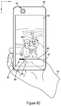
- FIGS. 7A-7D illustrate another example of a user input that controls different imaging operations performed by an electronic image capture device 720 via a graphical user interface.
- the example user input begins in FIG. 7A with a touch between an input element 717 and an input surface of a display 721 .
- the touch input is provided at a location 773 on the display 721 and in this example the input element 717 includes a thumb.
- the thumb is associated with a hand 716 that is supporting the electronic image capture device 720 so as to frame an image of the user 781 A and a second subject 781 B situated in close proximity to the user 781 A via a front facing camera module 701 of the device.
- FIG. 7A illustrates another example of a user input that controls different imaging operations performed by an electronic image capture device 720 via a graphical user interface.
- the example user input begins in FIG. 7A with a touch between an input element 717 and an input surface of a display 721 .
- the touch input is provided at a location 773 on the
- the front facing camera module 701 includes a first camera 702 and a second camera 704 .
- the example operation described with reference to FIGS. 7A-7D can be implemented in differently provisioned electronic image capture devices (e.g., using a rear facing camera module and/or using differently configured front facing camera modules than the example depicted in FIG. 7A ).
- the location 773 of the touch input can be selected by the user 781 A. That is, in some implementations, the user 781 A can initiate the example user input by touching any location along the input surface of display 721 .
- a graphical user interface may dictate a location of the touch input described below. That is to say, the display may persistently present one or more graphical user interface elements setting a location of touch input to control one or more imaging operations (e.g., a zoom level control and/or image frame capture control).
- a sub-portion of the input surface of the display 721 may be utilized to receive the touch input shown in FIG. 7A .
- the electronic image capture device 720 can be configured to enable the user 781 A to provide the input depicted in any location bounded within a lower half, upper half, quadrant, right most half, left most half, etc. of the display 721 .
- a graphical element 791 may be displayed at or near the location 773 of the touch input.
- the graphical element 791 can be displayed once a threshold length of time of the touch input has been met.
- the graphical element 791 can be configured once the initiated touch input has persisted for 0.5 seconds, or another amount of time that can indicate an intended touch or persistent touch.
- the graphical element 791 can include a first region 793 and a second region 795 .
- a zoom level of the camera module 701 can be controlled in response to a movement of the input element 717 relative to the first region 793 during a first portion of the user input described with reference to FIGS. 7A-7D .
- a location 796 of the touch input on the first region 793 in FIG. 7B is different than a location 798 of the touch input on the first region in FIG. 7C .
- the movement of the input element 717 relative to the first region depicted in FIGS. 7B and 7C can include a continuous translated touch input (e.g., a drag) across the display 721 along an arc.
- the movement can include a transition from a first touch to a second touch with a separation of the input element 717 from the display 721 there between.
- the first region 793 of the graphical element 791 can act as an arced slider or virtual dial to allow the user 781 A to provide a zoom level control input via a graphical user interface.
- an initial zoom level upon the initialization of the camera module 701 can be disposed evenly between a minimum and maximum zoom level that the camera module 701 can be controlled to.
- the graphical element 791 can be initially displayed such that a position of the initial touch input relative to first region 793 is between the relative ends of the illustrated arc.
- a default zoom level may be fully zoomed out (wide level) or fully zoomed in (tele level) and the graphical element 791 can be rendered accordingly such that it is convenient for the user to provide input to control the zoom level via the first region 793 , if needed.
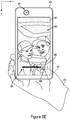
- a location 799 of touch input by the input element 717 has moved to the second region 795 of the graphical element 791 as compared to the location 798 shown in FIG. 7C .
- a second portion of the user input described with reference to FIGS. 7A-7D can include a second movement of the input element 717 between the first region 793 and the second region 795 .
- This second movement during the second portion of the user input can be provided to control an image capture operation once a desired zoom level has been reached based on the first portion of the user input. For example, as shown in the captured image frame 750 rendered on the display 721 in FIG.
- the user 781 A and the second subject 781 B are framed in the scene such that they are enlarged relative to FIG. 7A and such that the background stage at the depicted venue is also framed within the image frame 750 .
- the user 781 A can maintain a touch input at the second region 795 after moving the input element from the first region 793 to the second region to trigger a burst capture of multiple still image frames and/or to trigger a video capture mode.
- the movement of the input element 717 between FIGS. 7C and 7D can include a translated, continuous touch input (e.g., a drag) along the display 721 along a line segment extending between the location of touch input depicted in FIG. 7C and the location of touch input depicted in FIG. 7D .
- a translated, continuous touch input e.g., a drag
- the first portion (e.g., FIGS. 7A-7C ) of the user input to control the zoom level and the second portion (e.g., FIGS. 7C-7D ) of the user input can form a continuous touch input including at least two translations. That is to say, the first portion and the second portion can be arranged in temporal series with no interruption and/or intervening portion there between.
- a time and level of coordination required to transition between a zoom level control input (e.g., the first portion) and an image capture control input (e.g., the second portion) can be minimized as compared to the examples described with reference to FIGS. 1 and 2 .
- the movements depicted in FIGS. 7B-7D need not be continuous touch translations (e.g., one or more drags along the display) and the first portion and the second portion can be arranged with intervening portions there between so as to not be arranged directly in temporal series.
- FIGS. 8A-8E schematically depict another example of imaging operations performed in response to a user input provided via a graphical user interface.
- FIG. 8A illustrates an electronic image capture device 820 being held by a hand 816 of a user 881 A. Similar to FIGS. 7A-7D , FIG. 8A illustrates an example of image frame capture operation using a front facing camera module 801 having a single camera 802 configured to receive image frames depicting the user 881 A and a young child 881 B.
- FIG. 8B shows a touch input on the input surface of the display 821 provided by the input element 817 .
- a graphical element 891 is rendered.
- the electronic image capture device 820 can be configured to output a graphical user interface including additional graphical elements.
- a graphical user interface can be provided to receive touch inputs related to other imaging and/or device control operations than the examples discussed herein.
- the graphical element 891 includes a first region 893 , a second region 895 , and a third region 894 .
- the first region 893 includes a slider bar and the third region 894 includes a sliding indicator.
- the slider bar and the sliding indicator can be used to receive an input to control a zoom level. For example, a touch input can move between positions along the slider bar to adjust a zoom level of the camera module 801 between a minimum zoom level (“ ⁇ ” or “w”) and a maximum zoom level (“+” or “t”).
- the sliding indicator of the third region 894 can provide feedback to the user regarding a location along the display 821 of sensed touch input and/or of a current zoom level applied relative to a range of zoom level control.
- a continuous touch input can be applied to move the third region 894 relative to the first region 893 (e.g., a drag gesture).
- a zoom level can be adjusted by providing discrete touch inputs along the slider bar (e.g., separate touch inputs). Persons with skill in the art will appreciate that other input types (e.g., non-touch gestures) can be received to adjust a zoom level via the slider bar and sliding indicator.
- FIG. 8C a position of the received touch input along the slider bar of the first region 893 as indicated by the sliding indicator of the third region 894 has moved relative to the position shown in FIG. 8B .
- the sliding indicator is positioned closer to the minimum zoom level as compared to the position of touch input along the slider bar in FIG. 8B .
- a zoom level of the preview image represented on the display 821 has decreased in FIG. 8C .
- a position of the second region 895 has also moved between FIG. 8B in response to the change in touch position.
- FIG. 8D shows yet another position of the received touch input along the slider bar of the first region 893 .
- the sliding indicator of the third region 894 is positioned closer to the maximum zoom level as compared to the position of the touch input along the slider bar in FIG. 8B .
- a zoom level of the preview image on the display 821 has increased in FIG. 8D relative to FIGS. 8C and 8B .
- the second region 895 can include a capture or shutter graphical element that can receive an input from the user 881 A to cause the camera module 801 to capture an image frame.
- a user interface of an electronic image capture device so as to limit an amount of time and/or coordination required by a user to transition between input types that control separate imaging operations.
- a location of the second region 895 of the graphical element 891 moves in response to a change in location of the slider indicator of the third region 894 .
- the second region 895 moves in concert with the third region 894 relative to the first region 893 based on a location of the touch input received from the input element 817 by the display 821 .
- an x-y coordinate distance between the sliding indicator of the third region 894 and the second region 895 is maintained over time regardless of where the sliding indicator is positioned relative to the slider bar of the first region 893 .
- a relative direction in the x-y plane between the sliding indicator and the second region 895 is also persistent even as the sliding indicator moves along the slider bar. That is to say, the second region 895 is updated along with, and tracks the position of, the third region 894 such that it is always directly below (in a y-axis dimension) the sliding indicator.
- a distance and/or direction between the second region 895 and the third region 894 can be selected and/or adjusted by a user. For example, a user may prefer an upward swipe or directional relation between the regions. Additionally, a user may adjust a distance to reduce a required time to transition between the two regions and/or to increase a distance so as to inhibit inadvertent selection.
- FIG. 8E an advantage and improved user experience provided by the movement of the second region 895 relative to the first region 893 can be observed.
- the user 881 A has moved the input element 817 to provide a touch input at the second region 895 .
- the electronic image capture device 820 can be configured to cause the camera module 801 to capture an image frame 850 in response to the touch input at the second region 895 .
- additional or alternative imaging operations can be controlled in response to the user input via the second region 895 of the graphical element 891 .
- a distance d between the third region and the second is maintained throughout the user input operation.
- FIGS. 8A-8E an amount of coordination and time required to transition between the first input to control the zoom level ( FIGS. 8B-8D ) and a second input to control the image capture ( FIG. 8E ) can be reduced as compared to the examples discussed above with reference to FIGS. 1 and 2 .
- a user of the device depicted in FIGS. 8A-8E is more likely to capture an image frame as intended because it is less likely that the scene changes between the first input and the second input and/or because hand shake can be limited due to a reduction in coordinational complexity.
- the user 881 A in FIGS. 8A-8E is holding the electronic image capture device 820 in a portrait mode configuration so as to frame himself, the young child 881 B, and a region of interest of a background portion of the scene (e.g., an infield of a baseball field positioned behind the child 881 B and user 881 A).
- a region of interest of a background portion of the scene e.g., an infield of a baseball field positioned behind the child 881 B and user 881 A.
- a greater range of motion of an input element 817 relative to the display 821 can be utilized to control a first imaging operation without increasing a level of manual dexterity and/or coordination required by the user 881 A as compared to the implementation depicted in FIGS. 7A-7D .
- a maximum translation dimension of the slider bar of the first region 893 can be higher than a maximum arc length of the first region 793 in FIGS.
- the arc shape of the first region 793 depicted in FIGS. 7B-7D may facilitate a translation length that is more comfortable to provide input over by a user than the same length arranged in a linear dimension since an x-axis minimum and a x-axis maximum of the arc shape may be closer to each other than the x-axis minimum and x-axis maximum of an equal linear translation span.
- a region of a graphical element can be spaced apart from another region of the graphical element along an input surface such that the regions are not contiguous and/or do not abut one another along the input surface.
- the first and second regions 893 , 895 are spaced apart from the third region 894 along the surface of the display 821 by a distance d.
- the spatial position and/or arrangement of regions of the graphical element can be selected to inhibit inadvertent contact or selection by a user.
- first and second regions 893 , 895 apart from the third region 894 a user may more easily provide input via the first and second regions (e.g., to control a zoom level) without inadvertently contacting the third region 894 so as to provide input related to a separate imaging operation (e.g., to control a capture of an image frame).
- this selection can be applied to any of the embodiments disclosed herein.
- the first region 793 of the graphical element 791 in FIG. 7B abuts the second region 795 of the graphical element, those having skill in the art will appreciate that the first and second regions can be optionally spaced from one another along the surface of the display 721 .
- the responsivity to input of the touch stack can vary across the regions of the graphical element 791 .
- a portion of the first region 793 that is proximate to the second region 795 can be less responsive or sensitive to user input than a more distal portion of the first region 793 .
- an electronic image capture device can be configured to receive different types of user inputs to control a common imaging operation (e.g., to control a zoom level) depending on which camera module is being utilized. For example, a first input type (e.g., a twist as depicted in FIG.
- a zoom level when a rear facing camera module is receiving image data
- a second input type e.g., a linear or non-linear translation as illustrated in FIGS. 7 and 8
- a user may be able to assign different input types to control a common imaging operation depending on which camera module is being utilized.
- FIGS. 9A-9E depict an additional example of imaging operations performed in response to user input provided via an input surface of a device 920 .
- FIG. 9A includes an electronic image capture device 920 including a display 921 .
- the display 921 includes a preview image of a scene including a first subject 983 A and a second subject 983 B in a scene.
- the preview image is based on image data received by a rear facing camera module of the device 920 (not shown in FIG. 9A ) and can form part of a preview stream utilized by a user to frame and compose the scene before capturing one or more image frames (e.g., before capturing one or more video sequences and/or one or more still image frames).
- a first hand 912 of a user is illustrated as supporting and positioning the electronic image capture device 920 and a second hand 916 of the user is used as an input element to provide an input via an input surface of the display 921 .
- a first digit of the second hand 916 e.g., a forefinger
- a second digit e.g., a thumb
- the example user input depicted in FIGS. 9A-9E can begin by positioning the first and second structures 918 , 919 of the user input element relative to the display 921 .
- the first and second structures 918 , 919 can be positioned by the user to touch an input surface of the display 921 at selected locations.
- the first and second structures 918 , 919 can be positioned to hover relative to the display 921 (e.g., in devices with contactless or non-tactile gesture input capabilities).
- a graphical element 991 can optionally be rendered on the display 921 to provide feedback to the user related to the positioning of the first and second structures.
- the graphical element 991 can include a first region 993 and a second region 995 .
- the first region 993 can include a bounding box formed such that opposite corners of the box lie below sensed positions of the first and second structures 918 , 919 of the user input element.
- other geometries can be implemented (e.g., other polygons or shapes including triangles, circles, squares, trapezoids, etc.).
- the first region 993 can include any suitable shape or geometry. For example, a circle, a square, a stylized icon, an asymmetrical shape with internal detail, etc.
- the first and second regions 993 , 995 can be selected to provide indicia to a user related to: 1) a sensed location of the first and second structures 918 , 919 as used to control a first imaging operation and 2) a location for input related to a second imaging operation.
- the example user input continues with a coordinated movement of the first and second structures 918 , 919 of the user input element relative to the display 921 and relative to one another.
- the first structure 918 has translated along an input surface of the display 921 between the position depicted in FIG. 9B and the position depicted in FIG. 9C .
- the second structure 919 has translated along an input surface of the display 921 between the position depicted in FIG. 9B and the position depicted in FIG. 9C .
- the direction of movement of the first structure 918 is opposite the direction of movement of the second structure 919 in x-axis coordinates and y-axis coordinates.
- FIGS. 9B and 9C depict an example of an expansion of a pinch gesture (e.g., an unpinch) applied via touch on the display 921 .
- a pinch gesture e.g., an unpinch
- FIG. 9C it can be observed that the depicted movement or pinch gesture can be used to control a zoom level applied by the rear facing camera module of the electronic image capture device 920 .
- the expansion of the distance between the first and second structures 918 , 919 as represented by the first region 993 results in an increased zoom level or zoom-in between FIGS. 9B and 9C .
- the example user input continues with another movement of the first and second structures 918 , 919 of the user input element relative to the display 921 and relative to one another.
- the first structure 918 and second structure 919 have translated along the display back toward one another (e.g., in a direction toward the positions illustrated in FIG. 9B ).
- an example pinch and/or expansion of a pinch gesture or series of gestures can be used to control an imaging operation (e.g., to control a zoom level adjustment operation).
- a location of the second region 995 of the graphical element 991 moves in response to a change in shape and/or position of the first region 993 . More specifically, a position of the second region 995 relative to a corner of the first region 993 remains constant even as the first region changes in shape and/or size as the first and second structures 918 , 919 move relative to the display 921 . As a result, an x-y coordinate distance and direction between the second structure 919 and the second region 995 is maintained as the locations of sensed input associated with the first and second structures 918 , 919 move.
- the electronic image capture device 920 can be configured such that the second region 995 tracks a predetermined portion of the first region 993 .
- the second region 995 can be considered as tracking a location of a lower, left corner of the first region 993 .
- a portion of the first region 993 that is tracked by the second region 995 can be selected by a user.
- a user may select a different corner of the depicted first region 993 that the second region 995 can track.
- FIGS. 9A-9E can be practiced without the graphical element 991 .
- a user may provide the illustrated inputs, or equivalents thereof, without one or more of the first and second regions 993 , 995 being rendered by the display 921 .
- the imaging operation discussed below with reference to FIG. 9E can be controlled by a selection of a display area that is persistently positioned in terms of x-y coordinate distance and direction relative to a sensed position of one or both of the first and second structures 918 , 918 .
- FIG. 9E an advantage and improved user experience provided by the movement of the second region 995 based on the movement of the first and second structures 918 , 919 of the user input element is shown.
- the user has moved the second structure 919 to provide a touch input at the second region 995 .
- the electronic image capture device 920 can be configured to cause the rear facing camera module to capture an image frame 950 in response to the touch input at the second region 995 .
- additional or alternative imaging operations can be controlled in response to the user input via the second region 995 of the graphical element 991 . For example, flash photography, AF, and/or AR operations can be controlled. In any case, because the movement of the second region 995 between FIGS.
- FIGS. 9B and 9D tracks the movement of touch input of the first and second structures 918 , 919 represented by the first region 993 (e.g., bounding box), a distance is maintained between the second region and a portion of the first region (e.g., the lower, left corner) throughout the user input operation.
- the first region 993 e.g., bounding box
- a distance is maintained between the second region and a portion of the first region (e.g., the lower, left corner) throughout the user input operation.
- an amount of coordination and time required to transition between the first input to control the zoom level ( FIGS. 9B-9D ) and a second input to control the image capture ( FIG. 9E ) can be reduced as compared to the examples discussed above with reference to FIGS. 1 and 2 .
- a first imaging operation based on the locations of input of the first and second structures 918 , 919 can be paused or concluded in response to an independent movement of one the first and second structures while the other structure maintains a touch input without moving relative to the input surface of the display 921 (e.g., while the other structure remains stationary relative to the display).
- the first structure 918 maintains a touch input on the display 921 and does not move in position between FIGS. 9D and 9E .
- 9B-9E can be paused to allow the user to select the second region 995 to initiate the second imaging operation (e.g., image frame capture). Stated differently, an independent movement of one of the structures can pause a relative movement of the second region 995 relative to the position of the moving structure so as to allow the user to select a still, unmoving region.
- Those having skill in the art will appreciate that other techniques can be utilized to signal a user's intent to transition between imaging operations and that the user input depicted in FIGS. 9B-9E can be achieved by maintaining touch input by both of the first and second structures 918 , 919 throughout the user input or can be achieved by providing intermittent or non-continuous touch input.
- FIG. 10A includes an example electronic image capture device 1020 that is supported and positioned by a first hand 1012 of a user to frame a scene.
- Preview image frames depicting the scene are provided by a display 1021 which optionally outputs a graphical element 1091 including a bounding box 1093 sized and shaped in response to sensed input positions of first and second structures 1018 , 1019 (e.g., thumb and forefinger) of a second hand 1016 of the user.
- first and second structures 1018 , 1019 e.g., thumb and forefinger
- the first and second structures 1018 , 1019 can be manipulated relative to one another and relative to an input surface of the display 1021 so as to provide input relating to an imaging operation.
- a zoom level control operation is performed in response to an expanded pinch gesture performed between FIG. 10A and FIG. 10B . That is, a zoom level is increased by the movement of the first and second structures 1018 , 1019 away from each other and along the display 1021 .
- multi-touch gestures can be implemented to control an imaging operation (e.g., to control a zoom level adjustment).
- the example movement of the first and second structures 1018 , 1019 illustrated in FIGS. 10A and 10B can be considered a first type of user input received during a first portion of a user input with an imaging operation being controlled in response to the first type of user input.
- FIG. 10C illustrates a release of the first and second structures 1018 , 1019 of the second hand 1016 from the display 1021 .
- the release includes a separation 1061 between the first and second structures 1018 , 1019 and the input surface of the display 1021 .
- a second imaging operation performed by the electronic image capture device 1020 can be performed.
- the release of the first and second structures 1018 , 1019 can form a second type of user input that causes an image frame 1050 of the scene to be captured. In this way, it will be understood, similar to the examples described above with reference to FIGS.
- a first portion of the user input can include a first type of input (e.g., a dragging movement of one or more structures along an input surface) to control a first imaging operation and a second portion of the user input can include a separate type of input (e.g., a different type of movement along the input surface and/or a release from the input surface) to control a second imaging operation.
- a user experience when controlling different imaging operations in succession can be improved by minimizing a time and/or coordination required to transition between an input type to control a first imaging operation and an input type to control a second imaging operation.
- FIG. 11 is a flow chart illustrating an example operation 1100 for controlling a first imaging operation and a second imaging operation in response to a continuous user input.
- the example operation 1100 can be implemented by the electronic image capture device 400 of FIG. 4 . Further, those having skill in the art will appreciate that the operation 1100 can be implemented in other example devices.
- the operation 1100 begins at block 1101 with receiving, from a user input surface, a continuous user input including a first portion and a second portion.
- the user input can be received by a processor.
- processor 406 of the example device 400 of FIG. 4 the processor can be coupled to a camera module, the user input surface, and a memory.
- the user input surface can be part of a touch-sensitive display.
- the example operation 1100 continues with controlling a first imaging operation based on a first input type including movement of an input element relative to the user input surface during the first portion.
- the first imaging operation includes a zoom level adjustment operation and the zoom level adjustment can be reflected in a preview stream that is displayed during the first portion.
- the first input type can include a twist of the input element relative to the user input surface and/or a translation of the input element relative to the user input surface.
- the input element can include one or more fingers or a stylus.
- the operation 1100 continues at block 1105 with controlling a second imaging operation based on a second input type received during the second portion.
- the second imaging operation can optionally be a different type of imaging operation than the first imaging operation.
- the second imaging operation can include an AF operation, a flash photography operation, an AE operation, an image capture operation, etc.
- the second input type can include a release of the input element from the user input surface and/or a translation of the input element relative to the user input surface.
- the operation can include causing a touch-sensitive display including the user input surface to display one or more graphical user interface elements.
- a graphical user interface element can be displayed in a predetermined and persistent location or a location of the graphical user interface element can be based on a relative position of the user interface element when the user input is initiated.
- the graphical user interface element can include a first region and a second region.
- the first input type can include movement of the input element over at least a portion of the first region and the second input type can include movement along the user input surface between the first region and the second region.
- movement of the input element during the first portion can cause the second region to move relative to the first region during the first portion.
- movement of the second region during the first portion can track a location of the input element relative to the user input surface as the input element moves relative to the first region.
- a device implementing the example operation 1100 of FIG. 11 can include two or more camera modules.
- the first and second imaging operations can be associated with a first camera module and other imaging operations associated with a second camera can be controlled in response to a second user input.
- the operation can optionally include receiving a second continuous user input including a first portion and a second portion, and controlling a first imaging operation associated with the second camera module based on a first input type received during the first portion of the second continuous user input.
- the first input type received during the first portion of the second continuous user input can be similar or different than the first input type received during the first portion of the first continuous user input.
- the first imaging operation associated with the second camera module can be similar or different than the first imaging operation performed in response to the first portion of the continuous user input of block 1101 .
- different camera modules e.g., front and rear facing camera modules on an example device
- the first imaging operation associated with each camera module can relate to a zoom level adjustment.
- a receivable range of motion to control the first imaging operation associated with the first camera module can be different than a receivable range of motion to control the first imaging operation associated with the second camera module to account for differences in input elements (e.g., a thumb vs. a forefinger) that may be expected for each camera module.
- FIG. 12 is a flow chart illustrating another example operation 1200 for controlling a first imaging operation and a second imaging operation.
- the operation 1200 begins at block 1201 with causing a display to output a graphical user interface element including a first region.
- the graphical user interface element can be part of a graphical user interface that is output by a touch-sensitive display of a device that also includes a memory, a processor, and a camera module.
- the operation 1200 continues with receiving, from a user input surface of the display, a first user input type including movement of an input element relative to the user input surface.
- the input element can include a digit of a hand (e.g., a thumb and/or finger) or a stylus.
- the movement of the input element relative to the user input surface can include a continuous tactile or touch input (e.g., a drag touch gesture).
- a contact between the input element and the user input surface during the first user input type can be intermittent or the input element may provide a touchless gesture or input.
- the first input type can include different forms of movement of the input element relative to the user input surface. For example, a twist and/or a translational movement.
- Block 1205 of operation 1200 includes controlling a first imaging operation based on the first input type.
- the first imaging operation can include an AF operation, an AE operation, a flash photography operation, a region of interest tracking operation, a camera mode selection operation, and/or a zoom level adjustment operation.
- the processor can optionally be configured to cause the display to output a preview stream received from the camera module while the first input type is received to provide feedback to a user related to the first imaging operation.
- the first region is caused to move relative to the user input surface while the first input type is received.
- the movement of the first region can be based on a motion of the input element relative to user input surface.
- the first region can move to track a position of the input element relative to the user input surface. In this way, a distance and/or a direction between the input element and the first region can be maintained while the first input type is received.
- at least one of the distance and/or direction between the input element and the first region can be user adjustable and/or selectable. Those having skill in the art will appreciate that the movement of the first region can facilitate a transition between the first input type and a second input type.
- the graphical user interface element can include a second region.
- a second region of the graphical user interface element can be maintained in a stationary location relative to the user input surface while the first input type is received.
- the first input type can include a movement of the input element over at least a portion of the second region.
- the graphical user interface element can include a third region that moves relative to the second region and that tracks a movement of the first region. For example, a user may provide input via the third region and the third region can move along with the location of user input.
- the operation includes controlling a second imaging operation based on a second input type that is received after the first input type.
- the second input type includes a selection of the first region by the input element.
- the second imaging operation can include an image frame capture operation.
- the first input type can optionally be received during a first portion of a continuous user input with the second input type received during a second portion of the continuous user input.
- the second input type can include a translation of the input structure relative to the input surface.
- the input element can include a first structure (e.g., a finger) and a second structure (e.g., a thumb and/or finger).
- first and second structures can move relative to one another and relative to the user input surface while the first input type is received. Further, one of the first and second structures can remain stationary while the second input type is received while the other moves relative to the user input surface to select the first region of the graphical user interface element.
- the example operation 1200 of FIG. 12 can be implemented in an electronic image capture device (e.g., any of the devices described herein) including, or having access to, a camera module.
- the devices may be configured to output a first graphical user interface element to control imaging operations associated with a first camera module, and to output a second graphical user interface element to control imaging operations associated with the second camera module.
- the similar imaging operations related to the first and second camera modules can be controlled based on inputs received from differently configured graphical user interface elements.
- different imaging operations associated with each camera module can be controlled based on inputs received from similarly configured graphical user interface elements.
- circuits, systems, networks, processes, and other components may be shown as components in block diagram form in order not to obscure the embodiments in unnecessary detail.
- well-known circuits, processes, algorithms, structures, and techniques may be shown without unnecessary detail in order to avoid obscuring the embodiments.
- individual embodiments may be described as a process which is depicted as a flowchart, a flow diagram, a data flow diagram, a structure diagram, or a block diagram. Although a flowchart may describe the operations as a sequential process, many of the operations can be performed in parallel or concurrently. In addition, the order of the operations may be re-arranged.
- a process is terminated when its operations are completed, but could have additional steps not included in a figure.
- a process may correspond to a method, a function, a procedure, a subroutine, a subprogram, etc. When a process corresponds to a function, its termination can correspond to a return of the function to the calling function or the main function.
- any features described as modules or components may be implemented together in an integrated logic device or separately as discrete but interoperable logic devices. If implemented in software, the techniques may be realized at least in part by a computer-readable data storage medium comprising program code including instructions that, when executed, performs one or more of the methods described above.
- the computer-readable data storage medium may form part of a computer program product, which may include packaging materials.
- the computer-readable medium may comprise memory or data storage media, such as random access memory (RAM) such as synchronous dynamic random access memory (SDRAM), read-only memory (ROM), non-volatile random access memory (NVRAM), electrically erasable programmable read-only memory (EEPROM), FLASH memory, magnetic or optical data storage media, and the like.
- RAM random access memory
- SDRAM synchronous dynamic random access memory
- ROM read-only memory
- NVRAM non-volatile random access memory
- EEPROM electrically erasable programmable read-only memory
- FLASH memory magnetic or optical data storage media, and the like.
- the techniques additionally, or alternatively, may be realized at least in part by a computer-readable communication medium that carries or communicates program code in the form of instructions or data structures and that can be accessed, read, and/or executed by a computer, such as propagated signals or waves.
- the program code may be executed by a processor, which may include one or more processors, such as one or more digital signal processors (DSPs), general purpose microprocessors, an application specific integrated circuits (ASIC s), field programmable logic arrays (FPGAs), or other equivalent integrated or discrete logic circuitry.
- DSPs digital signal processors
- ASIC s application specific integrated circuits
- FPGAs field programmable logic arrays
- a general purpose processor may be a microprocessor; but in the alternative, the processor may be any conventional processor, controller, microcontroller, or state machine.
- a processor may also be implemented as a combination of computing devices, e.g., a combination of a DSP and a microprocessor, a plurality of microprocessors, one or more microprocessors in conjunction with a DSP core, or any other such configuration.
- processor may refer to any of the foregoing structure, any combination of the foregoing structure, or any other structure or apparatus suitable for implementation of the techniques described herein.
- functionality described herein may be provided within dedicated software modules or hardware modules configured for encoding and decoding, or incorporated in a combined video encoder-decoder (CODEC).
- the computer-readable medium may include transient media, such as a wireless broadcast or wired network transmission, or storage media (that is, non-transitory storage media), such as a hard disk, flash drive, compact disc, digital video disc, Blu-ray disc, or other computer-readable media.
- a network server (not shown) may receive encoded video data from the source device and provide the encoded video data to the destination device, e.g., via network transmission.
- a computing device of a medium production facility such as a disc stamping facility, may receive encoded video data from the source device and produce a disc containing the encoded video data. Therefore, the computer-readable medium may be understood to include one or more computer-readable media of various forms, in various examples.
Landscapes
- Engineering & Computer Science (AREA)
- Multimedia (AREA)
- Signal Processing (AREA)
- Human Computer Interaction (AREA)
- Studio Devices (AREA)
Abstract
Description
Claims (24)
Priority Applications (7)
| Application Number | Priority Date | Filing Date | Title |
|---|---|---|---|
| US15/830,851 US10594925B2 (en) | 2017-12-04 | 2017-12-04 | Camera zoom level and image frame capture control |
| PCT/US2018/063438 WO2019112908A1 (en) | 2017-12-04 | 2018-11-30 | Camera zoom level and image frame capture control |
| EP18826868.4A EP3721615A1 (en) | 2017-12-04 | 2018-11-30 | Camera zoom level and image frame capture control |
| SG11202003617QA SG11202003617QA (en) | 2017-12-04 | 2018-11-30 | Camera zoom level and image frame capture control |
| CN201880077320.3A CN111418202B (en) | 2017-12-04 | 2018-11-30 | Camera zoom level and image frame capture controls |
| TW107143315A TW201935911A (en) | 2017-12-04 | 2018-12-03 | Camera zoom level and image frame capture control |
| US16/849,936 US11483469B2 (en) | 2017-12-04 | 2020-04-15 | Camera zoom level and image frame capture control |
Applications Claiming Priority (1)
| Application Number | Priority Date | Filing Date | Title |
|---|---|---|---|
| US15/830,851 US10594925B2 (en) | 2017-12-04 | 2017-12-04 | Camera zoom level and image frame capture control |
Related Child Applications (1)
| Application Number | Title | Priority Date | Filing Date |
|---|---|---|---|
| PCT/US2018/063438 Continuation WO2019112908A1 (en) | 2017-12-04 | 2018-11-30 | Camera zoom level and image frame capture control |
Publications (2)
| Publication Number | Publication Date |
|---|---|
| US20190174055A1 US20190174055A1 (en) | 2019-06-06 |
| US10594925B2 true US10594925B2 (en) | 2020-03-17 |
Family
ID=64901084
Family Applications (2)
| Application Number | Title | Priority Date | Filing Date |
|---|---|---|---|
| US15/830,851 Active 2037-12-05 US10594925B2 (en) | 2017-12-04 | 2017-12-04 | Camera zoom level and image frame capture control |
| US16/849,936 Active 2038-10-14 US11483469B2 (en) | 2017-12-04 | 2020-04-15 | Camera zoom level and image frame capture control |
Family Applications After (1)
| Application Number | Title | Priority Date | Filing Date |
|---|---|---|---|
| US16/849,936 Active 2038-10-14 US11483469B2 (en) | 2017-12-04 | 2020-04-15 | Camera zoom level and image frame capture control |
Country Status (6)
| Country | Link |
|---|---|
| US (2) | US10594925B2 (en) |
| EP (1) | EP3721615A1 (en) |
| CN (1) | CN111418202B (en) |
| SG (1) | SG11202003617QA (en) |
| TW (1) | TW201935911A (en) |
| WO (1) | WO2019112908A1 (en) |
Cited By (5)
| Publication number | Priority date | Publication date | Assignee | Title |
|---|---|---|---|---|
| US11412132B2 (en) * | 2018-07-27 | 2022-08-09 | Huawei Technologies Co., Ltd. | Camera switching method for terminal, and terminal |
| US11483469B2 (en) * | 2017-12-04 | 2022-10-25 | Qualcomm Incorporated | Camera zoom level and image frame capture control |
| US20230396886A1 (en) * | 2019-03-18 | 2023-12-07 | Honor Device Co., Ltd. | Multi-channel video recording method and device |
| US20240340524A1 (en) * | 2022-07-07 | 2024-10-10 | Douyin Vision (Beijing) Co., Ltd. | Method, apparatus, device and storage medium for multimedia content shooting |
| US12225294B2 (en) | 2022-02-11 | 2025-02-11 | Aver Information Inc. | Automatic tracking method and tracking system applied to pan-tilt-zoom camera device |
Families Citing this family (11)
| Publication number | Priority date | Publication date | Assignee | Title |
|---|---|---|---|---|
| US10645272B2 (en) | 2017-12-04 | 2020-05-05 | Qualcomm Incorporated | Camera zoom level and image frame capture control |
| KR102537784B1 (en) * | 2018-08-17 | 2023-05-30 | 삼성전자주식회사 | Electronic device and control method thereof |
| WO2020059925A1 (en) * | 2018-09-21 | 2020-03-26 | 엘지전자 주식회사 | Mobile terminal |
| CN110225262A (en) * | 2019-06-25 | 2019-09-10 | 武汉华星光电半导体显示技术有限公司 | The light compensation method of taking pictures of special-shaped display screen and its front camera |
| EP4014475A1 (en) * | 2019-12-17 | 2022-06-22 | Google LLC | End-to-end camera architecture for display module |
| CN115104299A (en) * | 2020-02-21 | 2022-09-23 | 索尼集团公司 | Program, information processing method, and electronic device |
| JP2021136511A (en) * | 2020-02-25 | 2021-09-13 | キヤノン株式会社 | Imaging equipment, imaging systems, control methods, programs, and storage media |
| CN114979452B (en) * | 2021-02-20 | 2024-01-23 | 北京字跳网络技术有限公司 | Photography methods, devices, electronic equipment and storage media |
| KR20230023504A (en) * | 2021-08-10 | 2023-02-17 | 삼성전자주식회사 | Electronic device including flexible display and method of operating the same |
| US20230334279A1 (en) * | 2022-04-13 | 2023-10-19 | Ford Global Technologies, Llc | Vehicle access card with an integrated display |
| US12538018B2 (en) * | 2023-07-09 | 2026-01-27 | Motorola Mobility Llc | Capturing images using preferred camera settings in an electronic device |
Citations (19)
| Publication number | Priority date | Publication date | Assignee | Title |
|---|---|---|---|---|
| US20080165255A1 (en) | 2007-01-05 | 2008-07-10 | Apple Inc. | Gestures for devices having one or more touch sensitive surfaces |
| US20090015703A1 (en) | 2007-07-11 | 2009-01-15 | Lg Electronics Inc. | Portable terminal having touch sensing based image capture function and image capture method therefor |
| US20100289825A1 (en) | 2009-05-15 | 2010-11-18 | Samsung Electronics Co., Ltd. | Image processing method for mobile terminal |
| WO2011007264A1 (en) | 2009-07-17 | 2011-01-20 | Sony Ericsson Mobile Communications Ab | Using a touch sensitive display to control magnification and capture of digital images by an electronic device |
| US20110199517A1 (en) | 2010-02-12 | 2011-08-18 | Honeywell International Inc. | Method of showing video on a touch-sensitive display |
| EP2405299A2 (en) | 2010-07-07 | 2012-01-11 | Sony Corporation | Information processing device, information processing method, and program |
| US20120105588A1 (en) | 2010-10-28 | 2012-05-03 | Panasonic Corporation | Image capture device |
| US20120113216A1 (en) | 2010-11-04 | 2012-05-10 | Seen Seungmin | Mobile terminal and method of controlling an image photographing therein |
| EP2482179A2 (en) | 2011-01-28 | 2012-08-01 | Samsung Electronics Co., Ltd | Apparatus and method for controlling screen display in touch screen terminal |
| US20140063313A1 (en) * | 2012-09-03 | 2014-03-06 | Lg Electronics Inc. | Mobile device and control method for the same |
| US20140118563A1 (en) | 2012-10-28 | 2014-05-01 | Google Inc. | Camera zoom indicator in mobile devices |
| US20140368436A1 (en) | 2013-06-13 | 2014-12-18 | Microsoft Corporation | Classification of User Input |
| US20150326793A1 (en) * | 2014-05-06 | 2015-11-12 | Nokia Technologies Oy | Zoom input and camera information |
| US20160139774A1 (en) | 2014-11-18 | 2016-05-19 | Duelight Llc | System and method for computing operations based on a first and second user input |
| US20160381282A1 (en) | 2015-01-18 | 2016-12-29 | Samsung Electronics Co., Ltd. | Image processing apparatus and image processing method |
| US20170078564A1 (en) | 2008-07-24 | 2017-03-16 | Apple Inc. | Image capturing device with touch screen for adjusting camera settings |
| US20170090571A1 (en) | 2015-09-29 | 2017-03-30 | General Electric Company | System and method for displaying and interacting with ultrasound images via a touchscreen |
| US20180129224A1 (en) * | 2015-05-08 | 2018-05-10 | Lg Electronics Inc. | Mobile terminal and control method therefor |
| US20190174054A1 (en) | 2017-12-04 | 2019-06-06 | Qualcomm Incorporated | Camera zoom level and image frame capture control |
Family Cites Families (3)
| Publication number | Priority date | Publication date | Assignee | Title |
|---|---|---|---|---|
| JP2004109247A (en) * | 2002-09-13 | 2004-04-08 | Minolta Co Ltd | Digital camera, image processor, and program |
| TW201640280A (en) | 2015-05-15 | 2016-11-16 | 承風創意整合有限公司 | Method and system for operating article-oriented augmented reality, and computer-readable storing medium |
| US10594925B2 (en) * | 2017-12-04 | 2020-03-17 | Qualcomm Incorporated | Camera zoom level and image frame capture control |
-
2017
- 2017-12-04 US US15/830,851 patent/US10594925B2/en active Active
-
2018
- 2018-11-30 WO PCT/US2018/063438 patent/WO2019112908A1/en not_active Ceased
- 2018-11-30 SG SG11202003617QA patent/SG11202003617QA/en unknown
- 2018-11-30 EP EP18826868.4A patent/EP3721615A1/en active Pending
- 2018-11-30 CN CN201880077320.3A patent/CN111418202B/en active Active
- 2018-12-03 TW TW107143315A patent/TW201935911A/en unknown
-
2020
- 2020-04-15 US US16/849,936 patent/US11483469B2/en active Active
Patent Citations (20)
| Publication number | Priority date | Publication date | Assignee | Title |
|---|---|---|---|---|
| US20080165255A1 (en) | 2007-01-05 | 2008-07-10 | Apple Inc. | Gestures for devices having one or more touch sensitive surfaces |
| US20090015703A1 (en) | 2007-07-11 | 2009-01-15 | Lg Electronics Inc. | Portable terminal having touch sensing based image capture function and image capture method therefor |
| US20170078564A1 (en) | 2008-07-24 | 2017-03-16 | Apple Inc. | Image capturing device with touch screen for adjusting camera settings |
| US20100289825A1 (en) | 2009-05-15 | 2010-11-18 | Samsung Electronics Co., Ltd. | Image processing method for mobile terminal |
| WO2011007264A1 (en) | 2009-07-17 | 2011-01-20 | Sony Ericsson Mobile Communications Ab | Using a touch sensitive display to control magnification and capture of digital images by an electronic device |
| US20110199517A1 (en) | 2010-02-12 | 2011-08-18 | Honeywell International Inc. | Method of showing video on a touch-sensitive display |
| EP2405299A2 (en) | 2010-07-07 | 2012-01-11 | Sony Corporation | Information processing device, information processing method, and program |
| US20120011456A1 (en) | 2010-07-07 | 2012-01-12 | Takuro Noda | Information processing device, information processing method, and program |
| US20120105588A1 (en) | 2010-10-28 | 2012-05-03 | Panasonic Corporation | Image capture device |
| US20120113216A1 (en) | 2010-11-04 | 2012-05-10 | Seen Seungmin | Mobile terminal and method of controlling an image photographing therein |
| EP2482179A2 (en) | 2011-01-28 | 2012-08-01 | Samsung Electronics Co., Ltd | Apparatus and method for controlling screen display in touch screen terminal |
| US20140063313A1 (en) * | 2012-09-03 | 2014-03-06 | Lg Electronics Inc. | Mobile device and control method for the same |
| US20140118563A1 (en) | 2012-10-28 | 2014-05-01 | Google Inc. | Camera zoom indicator in mobile devices |
| US20140368436A1 (en) | 2013-06-13 | 2014-12-18 | Microsoft Corporation | Classification of User Input |
| US20150326793A1 (en) * | 2014-05-06 | 2015-11-12 | Nokia Technologies Oy | Zoom input and camera information |
| US20160139774A1 (en) | 2014-11-18 | 2016-05-19 | Duelight Llc | System and method for computing operations based on a first and second user input |
| US20160381282A1 (en) | 2015-01-18 | 2016-12-29 | Samsung Electronics Co., Ltd. | Image processing apparatus and image processing method |
| US20180129224A1 (en) * | 2015-05-08 | 2018-05-10 | Lg Electronics Inc. | Mobile terminal and control method therefor |
| US20170090571A1 (en) | 2015-09-29 | 2017-03-30 | General Electric Company | System and method for displaying and interacting with ultrasound images via a touchscreen |
| US20190174054A1 (en) | 2017-12-04 | 2019-06-06 | Qualcomm Incorporated | Camera zoom level and image frame capture control |
Non-Patent Citations (2)
| Title |
|---|
| International Search Report and Written Opinion-PCT/US2018/063438-ISA/EPO-dated May 6, 2019. |
| International Search Report and Written Opinion—PCT/US2018/063438—ISA/EPO—dated May 6, 2019. |
Cited By (10)
| Publication number | Priority date | Publication date | Assignee | Title |
|---|---|---|---|---|
| US11483469B2 (en) * | 2017-12-04 | 2022-10-25 | Qualcomm Incorporated | Camera zoom level and image frame capture control |
| US11412132B2 (en) * | 2018-07-27 | 2022-08-09 | Huawei Technologies Co., Ltd. | Camera switching method for terminal, and terminal |
| US11595566B2 (en) | 2018-07-27 | 2023-02-28 | Huawei Technologies Co., Ltd. | Camera switching method for terminal, and terminal |
| US11785329B2 (en) | 2018-07-27 | 2023-10-10 | Huawei Technologies Co., Ltd. | Camera switching method for terminal, and terminal |
| US20230396886A1 (en) * | 2019-03-18 | 2023-12-07 | Honor Device Co., Ltd. | Multi-channel video recording method and device |
| US12069375B2 (en) * | 2019-03-18 | 2024-08-20 | Honor Device Co., Ltd. | Multi-channel video recording method and device |
| US12549860B2 (en) | 2019-03-18 | 2026-02-10 | Honor Device Co., Ltd. | Multi-channel video recording method and device |
| US12225294B2 (en) | 2022-02-11 | 2025-02-11 | Aver Information Inc. | Automatic tracking method and tracking system applied to pan-tilt-zoom camera device |
| US20240340524A1 (en) * | 2022-07-07 | 2024-10-10 | Douyin Vision (Beijing) Co., Ltd. | Method, apparatus, device and storage medium for multimedia content shooting |
| US12520033B2 (en) * | 2022-07-07 | 2026-01-06 | Douyin Vision (Beijing) Co., Ltd. | Method, apparatus, device and storage medium for multimedia content shooting |
Also Published As
| Publication number | Publication date |
|---|---|
| US11483469B2 (en) | 2022-10-25 |
| CN111418202B (en) | 2021-11-02 |
| TW201935911A (en) | 2019-09-01 |
| SG11202003617QA (en) | 2020-06-29 |
| EP3721615A1 (en) | 2020-10-14 |
| WO2019112908A1 (en) | 2019-06-13 |
| CN111418202A (en) | 2020-07-14 |
| US20200244871A1 (en) | 2020-07-30 |
| US20190174055A1 (en) | 2019-06-06 |
Similar Documents
| Publication | Publication Date | Title |
|---|---|---|
| US10645272B2 (en) | Camera zoom level and image frame capture control | |
| US11483469B2 (en) | Camera zoom level and image frame capture control | |
| US12184965B2 (en) | Under-display camera and sensor control | |
| US9628699B2 (en) | Controlling a camera with face detection | |
| US10230901B2 (en) | Realtime capture exposure adjust gestures | |
| US10630895B2 (en) | Assist for orienting a camera at different zoom levels | |
| CN105009035B (en) | Strengthen touch input using gesture | |
| US8717381B2 (en) | Gesture mapping for image filter input parameters | |
| US9066005B2 (en) | Photographing device for displaying a manual focus guide and method thereof | |
| US9571739B2 (en) | Camera timer | |
| US11082620B2 (en) | Zoomed in region of interest |
Legal Events
| Date | Code | Title | Description |
|---|---|---|---|
| FEPP | Fee payment procedure |
Free format text: ENTITY STATUS SET TO UNDISCOUNTED (ORIGINAL EVENT CODE: BIG.); ENTITY STATUS OF PATENT OWNER: LARGE ENTITY |
|
| AS | Assignment |
Owner name: QUALCOMM INCORPORATED, CALIFORNIA Free format text: ASSIGNMENT OF ASSIGNORS INTEREST;ASSIGNORS:SRIVASTAVA, NITIN;BAGARIA, LUCKY;REEL/FRAME:044639/0037 Effective date: 20180116 |
|
| STPP | Information on status: patent application and granting procedure in general |
Free format text: NON FINAL ACTION MAILED |
|
| STPP | Information on status: patent application and granting procedure in general |
Free format text: RESPONSE TO NON-FINAL OFFICE ACTION ENTERED AND FORWARDED TO EXAMINER |
|
| STPP | Information on status: patent application and granting procedure in general |
Free format text: FINAL REJECTION MAILED |
|
| STPP | Information on status: patent application and granting procedure in general |
Free format text: DOCKETED NEW CASE - READY FOR EXAMINATION |
|
| STPP | Information on status: patent application and granting procedure in general |
Free format text: NOTICE OF ALLOWANCE MAILED -- APPLICATION RECEIVED IN OFFICE OF PUBLICATIONS |
|
| STPP | Information on status: patent application and granting procedure in general |
Free format text: PUBLICATIONS -- ISSUE FEE PAYMENT VERIFIED |
|
| STPP | Information on status: patent application and granting procedure in general |
Free format text: PUBLICATIONS -- ISSUE FEE PAYMENT VERIFIED |
|
| STCF | Information on status: patent grant |
Free format text: PATENTED CASE |
|
| AS | Assignment |
Owner name: QUALCOMM INCORPORATED, CALIFORNIA Free format text: ASSIGNMENT OF ASSIGNORS INTEREST;ASSIGNORS:SRIVASTAVA, NITIN;BAGARIA, LUCKY;REEL/FRAME:055040/0349 Effective date: 20210112 |
|
| MAFP | Maintenance fee payment |
Free format text: PAYMENT OF MAINTENANCE FEE, 4TH YEAR, LARGE ENTITY (ORIGINAL EVENT CODE: M1551); ENTITY STATUS OF PATENT OWNER: LARGE ENTITY Year of fee payment: 4 |