US10591864B2 - Image forming apparatus including a unit detachably mounted on an apparatus body via a locking member - Google Patents
Image forming apparatus including a unit detachably mounted on an apparatus body via a locking member Download PDFInfo
- Publication number
- US10591864B2 US10591864B2 US16/416,331 US201916416331A US10591864B2 US 10591864 B2 US10591864 B2 US 10591864B2 US 201916416331 A US201916416331 A US 201916416331A US 10591864 B2 US10591864 B2 US 10591864B2
- Authority
- US
- United States
- Prior art keywords
- image forming
- forming apparatus
- opening
- apparatus body
- closing cover
- Prior art date
- Legal status (The legal status is an assumption and is not a legal conclusion. Google has not performed a legal analysis and makes no representation as to the accuracy of the status listed.)
- Expired - Fee Related
Links
- 230000002093 peripheral effect Effects 0.000 description 14
- 210000000078 claw Anatomy 0.000 description 7
- 230000006835 compression Effects 0.000 description 6
- 238000007906 compression Methods 0.000 description 6
- 238000005516 engineering process Methods 0.000 description 4
- 238000010438 heat treatment Methods 0.000 description 4
- 238000000034 method Methods 0.000 description 4
- 238000003780 insertion Methods 0.000 description 2
- 230000037431 insertion Effects 0.000 description 2
- 230000001154 acute effect Effects 0.000 description 1
- 238000004140 cleaning Methods 0.000 description 1
- 230000000694 effects Effects 0.000 description 1
Images


Classifications
-
- G—PHYSICS
- G03—PHOTOGRAPHY; CINEMATOGRAPHY; ANALOGOUS TECHNIQUES USING WAVES OTHER THAN OPTICAL WAVES; ELECTROGRAPHY; HOLOGRAPHY
- G03G—ELECTROGRAPHY; ELECTROPHOTOGRAPHY; MAGNETOGRAPHY
- G03G21/00—Arrangements not provided for by groups G03G13/00 - G03G19/00, e.g. cleaning, elimination of residual charge
- G03G21/16—Mechanical means for facilitating the maintenance of the apparatus, e.g. modular arrangements
- G03G21/1604—Arrangement or disposition of the entire apparatus
- G03G21/1619—Frame structures
-
- G—PHYSICS
- G03—PHOTOGRAPHY; CINEMATOGRAPHY; ANALOGOUS TECHNIQUES USING WAVES OTHER THAN OPTICAL WAVES; ELECTROGRAPHY; HOLOGRAPHY
- G03G—ELECTROGRAPHY; ELECTROPHOTOGRAPHY; MAGNETOGRAPHY
- G03G21/00—Arrangements not provided for by groups G03G13/00 - G03G19/00, e.g. cleaning, elimination of residual charge
- G03G21/16—Mechanical means for facilitating the maintenance of the apparatus, e.g. modular arrangements
- G03G21/1604—Arrangement or disposition of the entire apparatus
- G03G21/1623—Means to access the interior of the apparatus
- G03G21/1633—Means to access the interior of the apparatus using doors or covers
Definitions
- the technology of the present disclosure relates to an image forming apparatus.
- an image forming apparatus such as a printer includes various units for forming an image on a sheet.
- the units include a fixing unit that heats and presses a toner image carried on a sheet to fix the toner image to the sheet, a drum unit having a photosensitive drum and the like for forming the toner image.
- These units are detachably mounted on an apparatus body via a locking member, are detached from the apparatus body by unlocking the locking member as needed, and are mounted again on the apparatus body after repair or replacement of new units.
- the locking member has a claw part that is engaged with a hook engaging part provided in the apparatus body.
- the fixing unit has a pair of handles interlocking with the locking member.
- the fixing unit is mounted on the apparatus body such that the pair of handles are directed to an opening side of the apparatus body.
- the opening is closed by an opening and closing cover.
- An image forming apparatus includes a predetermined unit, a locking member, and an opening and closing cover.
- the predetermined unit is detachably received in an image forming apparatus body.
- the locking member locks the predetermined unit in a state in which the predetermined unit is mounted in the image forming apparatus body.
- the opening and closing cover opens and closes an opening formed on a sidewall of the image forming apparatus body.
- the opening and closing cover is a rotary cover that opens and closes the opening by rotating about a shaft as a fulcrum.
- the predetermined unit is configured not to be detachable from the image forming apparatus body through the opening unless the opening and closing cover is detached from the image forming apparatus body.
- the image forming apparatus further includes a connection support member and an unlocking mechanism.
- the connection support member is detachably engaged with a rotation center part of the opening and closing cover to serve as the shaft and connects the opening and closing cover to the image forming apparatus body.
- the unlocking mechanism is configured to be able to release locking of the predetermined unit by the locking member.
- the connection support member is also used as a lock releasing member for operating the unlocking mechanism.
- FIG. 1 is a schematic configuration view illustrating an image forming apparatus in an embodiment.
- FIG. 2 is an external appearance perspective view illustrating the image forming apparatus in the embodiment.
- FIG. 3 is a view corresponding to FIG. 2 , which illustrates a state in which an opening and closing cover of the image forming apparatus in the embodiment is opened.
- FIG. 4 is an enlarged perspective view illustrating a rotation center part of the opening and closing cover.
- FIG. 5 is a sectional view taken along line V-V of FIG. 3 .
- FIG. 6 is an external appearance perspective view illustrating a connection support member of the opening and closing cover.
- FIG. 7 is a perspective view when a fixing unit locked by a locking member provided in an image forming apparatus body is viewed from the inside of the apparatus.
- FIG. 8 is a view corresponding to the section taken along line VIII-VIII of FIG. 7 , which illustrates a state in which the locking member is in a lock position where the fixing unit is locked.
- FIG. 9 is a view corresponding to FIG. 8 , which illustrates a state in which the locking of the fixing unit by the locking member is released.
- FIG. 10 is a plan view when the fixing unit is viewed from above.
- FIG. 11 is an enlarged view illustrating a part XI of FIG. 10 .
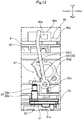
- FIG. 12 is a view corresponding to FIG. 11 , which illustrates a state in which the locking by the locking member is released.
- FIG. 13 is a view in the direction of the arrow XIII in FIG. 3 .
- FIG. 14 is an enlarged view illustrating a part XIV of FIG. 13 .
- FIG. 15 is a view corresponding to FIG. 14 , which illustrates a state in which the connection support member is assembled to a plate to be assembled.
- FIG. 1 is a schematic configuration view illustrating an example of an image forming apparatus 1 in an embodiment.
- the image forming apparatus 1 is a tandem type color printer.
- a front side and a rear side indicate a front side and a rear side (a front side and a back side in a direction perpendicular to the paper surface of FIG. 1 ) of the image forming apparatus 1
- a left side and a right side indicate a left side and a right side when the image forming apparatus 1 is viewed from the front side.
- the image forming apparatus 1 has an image forming apparatus body 2 having a rectangular box shape in appearance.
- the image forming apparatus body 2 receives an image forming unit 3 therein.
- the image forming unit 3 transfers an image to a sheet P and forms the image on the sheet P on the basis of image data transmitted from an external device such as a computer subjected to network connection and the like.
- an exposure device 4 is disposed to emit laser beams, and above the image forming unit 3 , a transfer belt 5 is disposed.
- a sheet feeding unit 6 is disposed to store the sheet P.
- a fixing unit 8 (an example of a predetermined unit) is disposed to perform a fixing process on the image transferred to and formed on the sheet P.
- a sheet discharge unit 9 is formed to discharge the sheet P subjected to the fixing process in the fixing unit 8 .
- the image forming apparatus 1 is provided therein with a sheet conveyance path T extending toward the sheet discharge unit 9 from the sheet feeding unit 6 .
- a rectangular opening 7 is formed in a right side wall 2 a adjacent to the sheet conveyance path T in the image forming apparatus 1 . The opening 7 is closed by a rotary opening and closing cover 20 .
- the image forming unit 3 includes four image forming units 10 disposed in a row along the transfer belt 5 .
- Each of the image forming units 10 has a photosensitive drum 11 .
- a charging device is disposed, and on the left side of each photosensitive drum 11 , a developing device 13 is disposed.
- a primary transfer roller 14 is disposed, and on the right side of each photosensitive drum 11 , a cleaning unit 15 is disposed to clean the peripheral surface of the photosensitive drum 11 .
- each photosensitive drum 11 is uniformly charged by the charging device 12 , and laser beams corresponding to each color based on the image data input from the aforementioned computer and the like are emitted to the charged peripheral surface of each photosensitive drum 11 from the exposure device 4 .
- an electrostatic latent image is formed on the peripheral surface of each photosensitive drum 11 .
- a developer is supplied to the electrostatic latent image from the developing device 13 , so that a toner image of yellow, magenta, cyan, or black is formed on the peripheral surface of each photosensitive drum 11 .
- These toner images are respectively superposed on and transferred to the transfer belt 5 by a primary transfer bias applied to the primary transfer roller 14 .
- a secondary transfer roller 16 is disposed on the right side of the transfer belt 5 .
- the secondary transfer roller 16 is disposed in the state of abutting the transfer belt 5 .
- the secondary transfer roller 16 interposes the sheet P conveyed from the sheet feeding unit 6 along the sheet conveyance path T between the secondary transfer roller 16 and the transfer belt 5 .
- a secondary transfer bias is applied to the secondary transfer roller 16 , so that the toner images on the transfer belt 5 are transferred to the sheet P by the applied secondary transfer bias.
- the reference numeral 17 denotes a resist roller that adjusts the timing of supplying the sheet P to the image forming unit 3
- the reference numeral 23 denotes a guide roller that guides the sheet P.
- the fixing unit 8 includes a heating roller 18 and a pressure roller 19 , wherein the sheet P is interposed by the heating roller 18 and the pressure roller 19 so as to be heated while being pressed. By so doing, the fixing unit 8 fixes the toner images, which have been transferred to the sheet P, to the sheet P.
- the sheet P subjected to the fixing process is discharged to the sheet discharge unit 9 .
- the opening and closing cover 20 is formed in an approximately rectangular plate shape in correspondence to the shape of the opening 7 .
- a guide member 21 is attached to an inner wall surface 20 a (an inner side surface of the image forming apparatus 1 ) of the opening and closing cover 20 .
- the guide member 21 has a sheet guide surface 21 a extending along the sheet conveyance path T.
- the sheet guide surface 21 a is provided with the secondary transfer roller 16 , the resist roller 17 , and the guide roller 23 .
- the opening and closing cover 20 is rotatable about its lower end edge as a fulcrum between a fully closed position and an open position. In the fully closed position, the opening 7 is closed by the opening and closing cover 20 as illustrated in FIG. 2 .
- the open position is a state in which the opening and closing cover 20 is tilted (rotated) by a predetermined angle from the fully closed position to the outside of the image forming apparatus body 2 as illustrated in FIG. 3 .
- the opening angle of the opening and closing cover 20 in the open position is limited by a stopper member (not illustrated).
- a stopper member not illustrated.
- the maximum opening angle of the opening and closing cover 20 is set to the extent that the fixing unit 8 is not able to pass through between the opening and closing cover 20 and the image forming apparatus body 2 .
- the fixing unit 8 is not taken out of the image forming apparatus body 2 through the opening 7 unless the opening and closing cover 20 is detached from the image forming apparatus body 2 .
- FIG. 4 and FIG. 5 illustrate only the front cover support part 2 b.
- Each cover support part 2 b is formed in a cylindrical shape having a support hole 2 c.
- a support hole 20 b is formed coaxially with the support hole 2 c on both side surfaces of the lower end of the opening and closing cover 20 in the front and rear direction.
- a shaft 32 of a connection support member 30 is inserted into the support hole 2 c and the support hole 20 b. By so doing, the opening and closing cover 20 is rotatably supported to the shaft 32 .
- connection support member 30 has a rectangular plate part 31 and the shaft 32 protruding from one side surface of the plate part 31 .
- the shaft 32 is composed of a large diameter part 32 a on its proximal end side and a small diameter part 32 b on its distal end side.
- An outer peripheral surface of the large diameter part 32 a is fitted to an inner peripheral surface of the support hole 2 c of the cover support part 2 b.
- An outer peripheral surface of the small diameter part 32 b is fitted to an inner peripheral surface of the support hole 20 b of the opening and closing cover 20 .
- a plate-like knob 31 a protrudes from a surface of the plate part 31 opposite to the shaft 32 side.
- the plate-like knob 31 a faces the inner wall surface of the image forming apparatus body 2 with a slight gap therebetween. By so doing, the connection support member 30 is prevented from being pulled out by the inner wall surface of the image forming apparatus body 2 .
- the opening and closing cover 20 is moved to the open position, the connection support member 30 is exposed to the outside of the image forming apparatus body 2 . Consequently, a user can grasp the plate-like knob 31 a to pull out the connection support member 30 from the both support holes 2 c and 20 b (see the two-dot chain line of FIG. 5 ).
- the connection support member 30 is pulled out, there is no member for restricting the opening and closing cover 20 , so that the opening and closing cover 20 can be detached from the image forming apparatus body 2 .
- the fixing unit 8 is detachably mounted on the inner side of the opening and closing cover 20 in the image forming apparatus body 2 .
- the fixing unit 8 has a casing 80 that receives the heating roller 18 and the pressure roller 19 therein.
- the casing 80 has a hollow box shape extending in an axial direction of the heating roller 18 and the pressure roller 19 .
- the longitudinal direction of the casing 80 and the front and rear direction of the image forming apparatus body 2 coincide with each other.
- the casing is locked in the mounted state by a locking member 40 provided in the image forming apparatus body 2 .
- the casing 80 is provided on the upper surface thereof with an unlocking mechanism 81 for releasing the locking of the casing 80 by the locking member 40 .
- the unlocking mechanism 81 is driven by a dedicated lock releasing member.
- the connection support member 30 is available as the lock releasing member.
- the locking mechanism 70 has the locking member 40 and a compression coil spring 41 (an example of an urging member and illustrated only in FIG. 8 and FIG. 9 ) that urges the locking member 40 to a lock side.
- the locking member 40 is attached so as to be slidable in the front and rear direction with respect to the image forming apparatus body 2 .
- the locking member 40 has a slide plate part 40 a, a pair of protruding pieces 40 b, and a pair of claw parts 40 c.
- the slide plate part 40 a has a vertical plate shape extending in the front and rear direction.
- the slide plate part 40 a is guided so as to be movable in the front and rear direction by a guide member (not illustrated) provided in the image forming apparatus body 2 .
- a rectangular parallelepiped block part 40 d is integrally formed on a part near the rear side of the slide plate part 40 a.
- a pressed part 40 e protrudes from an upper surface of the block part 40 d to receive pressing force in a lock releasing direction by the unlocking mechanism 81 .
- each protruding piece 40 b protrude from both ends of the slide plate part 40 a in the front and rear direction to the fixing unit 8 side (right side).
- each protruding piece 40 b is inserted into the insertion holes 80 a formed on the sidewall of the casing 80 .
- the pair of claw parts 40 c are formed at the distal ends of the protruding pieces 40 b.
- the compression coil spring 41 is disposed in a compressed state between a rear end of the locking member 40 and a rear wall of the image forming apparatus body 2 . Furthermore, the compression coil spring 41 always urges the locking member 40 to the front side.
- the locking member 40 is urged to the front side by the compression coil spring 41 , so that the pair of claw parts 40 c are engaged with engaged block parts 80 b formed on an inner wall surface of the casing 80 (see FIG. 8 ).
- the locking member 40 is moved to the rear side against the urging force of the compression coil spring 41 from this state, the engagement between the pair of claw parts 40 c and the engaged block parts 80 b is released as illustrated in FIG. 9 .
- the locking of the fixing unit 8 by the locking member 40 is released, so that the fixing unit 8 enters an unlocked state.
- the unlocking mechanism 81 is a mechanism for releasing the locking of the fixing unit 8 by the locking member 40 .
- the unlocking mechanism 81 has a columnar protruding pin part 80 c protruding from the upper surface of the casing 80 , and a swing member 82 swingably supported to the protruding pin part 80 c.
- the swing member 82 has a cylindrical part 82 a, a first protruding piece 82 b, and a second protruding piece 82 c.
- the cylindrical part 82 a is externally fitted to the protruding pin part 80 c so as to be swingable.
- the first protruding piece 82 b protrudes radially outward from an outer peripheral surface of the cylindrical part 82 a.
- the first protruding piece 82 b extends parallel to the front and rear direction.
- the second protruding piece 82 c also protrudes radially outward from the outer peripheral surface of the cylindrical part 82 a.
- the second protruding piece 82 c is disposed at an acute angle (for example, 60°) with respect to the first protruding piece 82 b when viewed from above.
- a distal end of the second protruding piece 82 c is slightly bent to have a plate shape perpendicular to the slide direction (the front and rear direction) of the locking member 40 .
- the distal end of the second protruding piece 82 c is located on the front side of the pressed part 40 e of the locking member 40 and does not abut the pressed part 40 e.
- the swing member 82 rotates in the clockwise direction of the drawing as illustrated in FIG. 12 .
- the distal end of the second protruding piece 82 c presses the pressed part 40 e of the locking member 40 rearward, so that the locking member 40 slides rearward.
- the operating force F is applied by assembling/pushing the connection support member 30 to/into a plate 2 e to be assembled (a part to be assembled).
- the plate 2 e to be assembled is vertically installed on a horizontal plate part 2 d fixed to a frame member of the image forming apparatus body 2 .
- the horizontal plate part 2 d is located in the vicinity of the upper side of a mounting space of the fixing unit 8 .
- the plate 2 e to be assembled is disposed so as to face the opening 7 .
- the plate 2 e to be assembled is exposed to the outside through the opening 7 by detaching the opening and closing cover 20 .
- the plate 2 e to be assembled has a rectangular plate shape that is long in the front and rear direction.
- the plate 2 e to be assembled is formed at the front end thereof with a fitting hole 2 f through which the shaft 32 of the connection support member 30 is inserted.
- connection support member 30 When the connection support member 30 is assembled to the plate 2 e to be assembled, the shaft 32 of the connection support member 30 is first inserted into the fitting hole 2 f from the distal end thereof. When the outer peripheral surface of the large diameter part 32 a of the shaft 32 comes to the inner peripheral surface of the fitting hole 2 f, the distal end surface of the shaft 32 abuts the first protruding piece 82 b of the swing member 82 . At this stage, there is a slight gap between the plate part 31 and the plate 2 e to be assembled. The connection support member 30 is pushed until the plate part 31 abuts the plate 2 e to be assembled, so that the operating force F (see FIG. 12 ) is applied to the first protruding piece 82 b of the swing member 82 from the distal end of the shaft 32 .
- the operating force F see FIG. 12
- the connection support member 30 is first detached from the cover support parts 2 b (see FIG. 5 ).
- the opening and closing cover 20 is brought into a free state and is detached from the image forming apparatus body 2 .
- the fixing unit 8 can be taken out of the image forming apparatus body 2 through the opening 7 , but it is also necessary to release the locking of the fixing unit 8 .
- the detached connection support member 30 is assembled to and pushed into the plate 2 e to be assembled in the aforementioned procedure.
- the unlocking mechanism 81 is operated to release the locking of the fixing unit 8 by the locking member 40 , and then the fixing unit 8 is detached from the image forming apparatus body 2 .
- connection support member 30 which is a component to be necessarily detached when detaching the fixing unit 8 , is used as a lock releasing component. In this way, it is possible to prevent the unlocking mechanism 81 from being erroneously operated when a user performs work other than the detachment work of the fixing unit 8 .
- the unlocking mechanism 81 is configured to release the locking of the fixing unit 8 by the locking member 40 by applying the predetermined operating force F via the connection support member 30 assembled to the plate 2 e to be assembled.
- the locking of the fixing unit 8 is not released unless a user intentionally applies the operating force F to the unlocking mechanism 81 via the connection support member 30 .
- a user intentionally applies the operating force F to the unlocking mechanism 81 via the connection support member 30 .
- the plate 2 e to be assembled has the fitting hole 2 f (a fitting part) fitted with the large diameter part 32 a (a specific shape part) of the shaft 32 of the connection support member 30 . Furthermore, the connection support member 30 is assembled to the plate 2 e to be assembled by fitting the large diameter part 32 a into the fitting hole 2 f.
- the unlocking mechanism 81 has the swing member 82 swingably supported to the protruding pin part 80 c, and the swing member 82 has the cylindrical part 82 a externally fitted to the protruding pin part 80 c and the first and second protruding pieces 82 b and 82 c protruding radially outward from the cylindrical part 82 a and spaced apart from each other in the circumferential direction.
- the unlocking mechanism 81 is configured such that the predetermined operating force F is input to the first protruding piece 82 b via the connection support member 30 , so that the second protruding piece 82 c rotates around the protruding pin part 80 c together with the cylindrical part 82 a and the locking member 40 is driven to the unlock position (the position of FIG. 9 ) against the urging force of the compression coil spring 41 .
- the unlocking mechanism can be compactly disposed to be fitted within the upper surface of the casing 80 of the fixing unit 8 .
- the fixing unit 8 has been described as an example of the predetermined unit; however, the technology of the present disclosure is not limited thereto.
- the predetermined unit for example, may be the image forming unit 10 , the developing device 13 and the like.
- the aforementioned embodiment has described an example in which the image forming apparatus 1 is a printer; however, the technology of the present disclosure is not limited thereto. That is, the image forming apparatus 1 may be a copy machine, a facsimile, a multifunctional peripheral (MFP) and the like.
- MFP multifunctional peripheral
Landscapes
- Physics & Mathematics (AREA)
- General Physics & Mathematics (AREA)
- Electrophotography Configuration And Component (AREA)
- Accessory Devices And Overall Control Thereof (AREA)
- Fixing For Electrophotography (AREA)
Abstract
Description
Claims (4)
Applications Claiming Priority (2)
| Application Number | Priority Date | Filing Date | Title |
|---|---|---|---|
| JP2018-098227 | 2018-05-22 | ||
| JP2018098227A JP7056377B2 (en) | 2018-05-22 | 2018-05-22 | Image forming device |
Publications (2)
| Publication Number | Publication Date |
|---|---|
| US20190361386A1 US20190361386A1 (en) | 2019-11-28 |
| US10591864B2 true US10591864B2 (en) | 2020-03-17 |
Family
ID=68613694
Family Applications (1)
| Application Number | Title | Priority Date | Filing Date |
|---|---|---|---|
| US16/416,331 Expired - Fee Related US10591864B2 (en) | 2018-05-22 | 2019-05-20 | Image forming apparatus including a unit detachably mounted on an apparatus body via a locking member |
Country Status (2)
| Country | Link |
|---|---|
| US (1) | US10591864B2 (en) |
| JP (1) | JP7056377B2 (en) |
Citations (3)
| Publication number | Priority date | Publication date | Assignee | Title |
|---|---|---|---|---|
| JP2011191400A (en) | 2010-03-12 | 2011-09-29 | Casio Electronics Co Ltd | Fixing unit locking device for image forming apparatus |
| US9158270B2 (en) * | 2012-12-05 | 2015-10-13 | Ricoh Company, Ltd. | Fixing device, image forming apparatus with same, and method of smoothly detaching and attaching fixing device from and to image forming apparatus |
| US9310724B2 (en) * | 2013-08-30 | 2016-04-12 | Canon Kabushiki Kaisha | Image heating unit, recording medium conveying unit and image forming apparatus |
Family Cites Families (7)
| Publication number | Priority date | Publication date | Assignee | Title |
|---|---|---|---|---|
| JPH10190911A (en) * | 1996-12-27 | 1998-07-21 | Murata Mach Ltd | Facsimile equipment |
| US5926671A (en) * | 1998-08-07 | 1999-07-20 | Xerox Corporation | Integral multi-function latch |
| JP3958117B2 (en) * | 2002-05-31 | 2007-08-15 | 株式会社リコー | Image forming apparatus |
| JP2006030420A (en) * | 2004-07-14 | 2006-02-02 | Fuji Xerox Co Ltd | Image forming apparatus |
| JP2007047404A (en) * | 2005-08-09 | 2007-02-22 | Canon Inc | Image forming apparatus |
| JP5012179B2 (en) * | 2007-04-27 | 2012-08-29 | 富士ゼロックス株式会社 | Image forming apparatus |
| JP5459735B2 (en) * | 2012-07-24 | 2014-04-02 | シャープ株式会社 | Image forming apparatus |
-
2018
- 2018-05-22 JP JP2018098227A patent/JP7056377B2/en not_active Expired - Fee Related
-
2019
- 2019-05-20 US US16/416,331 patent/US10591864B2/en not_active Expired - Fee Related
Patent Citations (3)
| Publication number | Priority date | Publication date | Assignee | Title |
|---|---|---|---|---|
| JP2011191400A (en) | 2010-03-12 | 2011-09-29 | Casio Electronics Co Ltd | Fixing unit locking device for image forming apparatus |
| US9158270B2 (en) * | 2012-12-05 | 2015-10-13 | Ricoh Company, Ltd. | Fixing device, image forming apparatus with same, and method of smoothly detaching and attaching fixing device from and to image forming apparatus |
| US9310724B2 (en) * | 2013-08-30 | 2016-04-12 | Canon Kabushiki Kaisha | Image heating unit, recording medium conveying unit and image forming apparatus |
Also Published As
| Publication number | Publication date |
|---|---|
| JP2019203965A (en) | 2019-11-28 |
| JP7056377B2 (en) | 2022-04-19 |
| US20190361386A1 (en) | 2019-11-28 |
Similar Documents
| Publication | Publication Date | Title |
|---|---|---|
| US9291993B2 (en) | Drive transmission mechanism and image forming apparatus provided with the same | |
| US7664427B2 (en) | Image forming apparatus with locking means | |
| US8000630B2 (en) | Developing cartridge, process cartridge, and electrophotographic image forming apparatus | |
| US20100239314A1 (en) | Color electrophotographic image forming apparatus | |
| US8032058B2 (en) | Electrophotographic image forming apparatus with developer cartridge lock member | |
| US20150063868A1 (en) | Image heating unit, recording medium conveying unit and image forming apparatus | |
| JP2009058711A (en) | Imaging cartridge and image forming apparatus | |
| US10261467B2 (en) | Image forming apparatus | |
| CN1954270A (en) | Functional unit and image forming apparatus including the functional unit | |
| CN106542355A (en) | Sheet feeding device and image forming apparatus | |
| JP3785951B2 (en) | Paper cassette and paper feeder | |
| JP7615910B2 (en) | CLEANING UNIT AND IMAGE FORMING APPARATUS - Patent application | |
| US10591864B2 (en) | Image forming apparatus including a unit detachably mounted on an apparatus body via a locking member | |
| JP2020086311A (en) | Image forming apparatus | |
| JPH08152756A (en) | Safety device for image forming device | |
| JP2008286829A (en) | Developing cartridge and electrophotographic image forming apparatus | |
| CN108873656B (en) | Image forming apparatus and storage device | |
| US8774678B2 (en) | Supporting cover for an image forming apparatus | |
| JP4273167B2 (en) | Electrophotographic image forming apparatus | |
| JP2019159088A (en) | Image forming apparatus and toner container | |
| CN215264384U (en) | image forming apparatus | |
| JP7746843B2 (en) | Developing device and image forming apparatus | |
| JP3720305B2 (en) | Image forming machine | |
| KR20200089617A (en) | Image Forming Apparatus | |
| US20250271810A1 (en) | Medium transport apparatus |
Legal Events
| Date | Code | Title | Description |
|---|---|---|---|
| AS | Assignment |
Owner name: KYOCERA DOCUMENT SOLUTIONS INC., JAPAN Free format text: ASSIGNMENT OF ASSIGNORS INTEREST;ASSIGNOR:IKETANI, TAKESHI;REEL/FRAME:049222/0141 Effective date: 20190514 |
|
| FEPP | Fee payment procedure |
Free format text: ENTITY STATUS SET TO UNDISCOUNTED (ORIGINAL EVENT CODE: BIG.); ENTITY STATUS OF PATENT OWNER: LARGE ENTITY |
|
| STPP | Information on status: patent application and granting procedure in general |
Free format text: NOTICE OF ALLOWANCE MAILED -- APPLICATION RECEIVED IN OFFICE OF PUBLICATIONS |
|
| STPP | Information on status: patent application and granting procedure in general |
Free format text: PUBLICATIONS -- ISSUE FEE PAYMENT RECEIVED |
|
| STPP | Information on status: patent application and granting procedure in general |
Free format text: PUBLICATIONS -- ISSUE FEE PAYMENT VERIFIED |
|
| STCF | Information on status: patent grant |
Free format text: PATENTED CASE |
|
| FEPP | Fee payment procedure |
Free format text: MAINTENANCE FEE REMINDER MAILED (ORIGINAL EVENT CODE: REM.); ENTITY STATUS OF PATENT OWNER: LARGE ENTITY |
|
| LAPS | Lapse for failure to pay maintenance fees |
Free format text: PATENT EXPIRED FOR FAILURE TO PAY MAINTENANCE FEES (ORIGINAL EVENT CODE: EXP.); ENTITY STATUS OF PATENT OWNER: LARGE ENTITY |
|
| STCH | Information on status: patent discontinuation |
Free format text: PATENT EXPIRED DUE TO NONPAYMENT OF MAINTENANCE FEES UNDER 37 CFR 1.362 |
|
| FP | Lapsed due to failure to pay maintenance fee |
Effective date: 20240317 |