US10591203B2 - Refrigerator - Google Patents
Refrigerator Download PDFInfo
- Publication number
- US10591203B2 US10591203B2 US15/367,747 US201615367747A US10591203B2 US 10591203 B2 US10591203 B2 US 10591203B2 US 201615367747 A US201615367747 A US 201615367747A US 10591203 B2 US10591203 B2 US 10591203B2
- Authority
- US
- United States
- Prior art keywords
- support member
- inner case
- storage compartment
- insulation material
- coupled
- Prior art date
- Legal status (The legal status is an assumption and is not a legal conclusion. Google has not performed a legal analysis and makes no representation as to the accuracy of the status listed.)
- Active
Links
Images


Classifications
-
- F—MECHANICAL ENGINEERING; LIGHTING; HEATING; WEAPONS; BLASTING
- F25—REFRIGERATION OR COOLING; COMBINED HEATING AND REFRIGERATION SYSTEMS; HEAT PUMP SYSTEMS; MANUFACTURE OR STORAGE OF ICE; LIQUEFACTION SOLIDIFICATION OF GASES
- F25D—REFRIGERATORS; COLD ROOMS; ICE-BOXES; COOLING OR FREEZING APPARATUS NOT OTHERWISE PROVIDED FOR
- F25D25/00—Charging, supporting, and discharging the articles to be cooled
- F25D25/02—Charging, supporting, and discharging the articles to be cooled by shelves
- F25D25/024—Slidable shelves
- F25D25/025—Drawers
-
- F—MECHANICAL ENGINEERING; LIGHTING; HEATING; WEAPONS; BLASTING
- F25—REFRIGERATION OR COOLING; COMBINED HEATING AND REFRIGERATION SYSTEMS; HEAT PUMP SYSTEMS; MANUFACTURE OR STORAGE OF ICE; LIQUEFACTION SOLIDIFICATION OF GASES
- F25D—REFRIGERATORS; COLD ROOMS; ICE-BOXES; COOLING OR FREEZING APPARATUS NOT OTHERWISE PROVIDED FOR
- F25D11/00—Self-contained movable devices, e.g. domestic refrigerators
- F25D11/02—Self-contained movable devices, e.g. domestic refrigerators with cooling compartments at different temperatures
-
- F—MECHANICAL ENGINEERING; LIGHTING; HEATING; WEAPONS; BLASTING
- F25—REFRIGERATION OR COOLING; COMBINED HEATING AND REFRIGERATION SYSTEMS; HEAT PUMP SYSTEMS; MANUFACTURE OR STORAGE OF ICE; LIQUEFACTION SOLIDIFICATION OF GASES
- F25D—REFRIGERATORS; COLD ROOMS; ICE-BOXES; COOLING OR FREEZING APPARATUS NOT OTHERWISE PROVIDED FOR
- F25D23/00—General constructional features
- F25D23/02—Doors; Covers
- F25D23/04—Doors; Covers with special compartments, e.g. butter conditioners
-
- F—MECHANICAL ENGINEERING; LIGHTING; HEATING; WEAPONS; BLASTING
- F25—REFRIGERATION OR COOLING; COMBINED HEATING AND REFRIGERATION SYSTEMS; HEAT PUMP SYSTEMS; MANUFACTURE OR STORAGE OF ICE; LIQUEFACTION SOLIDIFICATION OF GASES
- F25D—REFRIGERATORS; COLD ROOMS; ICE-BOXES; COOLING OR FREEZING APPARATUS NOT OTHERWISE PROVIDED FOR
- F25D23/00—General constructional features
- F25D23/06—Walls
- F25D23/062—Walls defining a cabinet
-
- A—HUMAN NECESSITIES
- A47—FURNITURE; DOMESTIC ARTICLES OR APPLIANCES; COFFEE MILLS; SPICE MILLS; SUCTION CLEANERS IN GENERAL
- A47B—TABLES; DESKS; OFFICE FURNITURE; CABINETS; DRAWERS; GENERAL DETAILS OF FURNITURE
- A47B2210/00—General construction of drawers, guides and guide devices
- A47B2210/0002—Guide construction for drawers
- A47B2210/0029—Guide bearing means
- A47B2210/0037—Rollers
-
- A—HUMAN NECESSITIES
- A47—FURNITURE; DOMESTIC ARTICLES OR APPLIANCES; COFFEE MILLS; SPICE MILLS; SUCTION CLEANERS IN GENERAL
- A47B—TABLES; DESKS; OFFICE FURNITURE; CABINETS; DRAWERS; GENERAL DETAILS OF FURNITURE
- A47B2210/00—General construction of drawers, guides and guide devices
- A47B2210/0002—Guide construction for drawers
- A47B2210/0051—Guide position
- A47B2210/0056—Guide located at the bottom of the drawer
-
- A—HUMAN NECESSITIES
- A47—FURNITURE; DOMESTIC ARTICLES OR APPLIANCES; COFFEE MILLS; SPICE MILLS; SUCTION CLEANERS IN GENERAL
- A47B—TABLES; DESKS; OFFICE FURNITURE; CABINETS; DRAWERS; GENERAL DETAILS OF FURNITURE
- A47B2210/00—General construction of drawers, guides and guide devices
- A47B2210/0002—Guide construction for drawers
- A47B2210/0051—Guide position
- A47B2210/0059—Guide located at the side of the drawer
-
- A—HUMAN NECESSITIES
- A47—FURNITURE; DOMESTIC ARTICLES OR APPLIANCES; COFFEE MILLS; SPICE MILLS; SUCTION CLEANERS IN GENERAL
- A47B—TABLES; DESKS; OFFICE FURNITURE; CABINETS; DRAWERS; GENERAL DETAILS OF FURNITURE
- A47B2210/00—General construction of drawers, guides and guide devices
- A47B2210/17—Drawers used in connection with household appliances
- A47B2210/175—Refrigerators or freezers
-
- F—MECHANICAL ENGINEERING; LIGHTING; HEATING; WEAPONS; BLASTING
- F25—REFRIGERATION OR COOLING; COMBINED HEATING AND REFRIGERATION SYSTEMS; HEAT PUMP SYSTEMS; MANUFACTURE OR STORAGE OF ICE; LIQUEFACTION SOLIDIFICATION OF GASES
- F25D—REFRIGERATORS; COLD ROOMS; ICE-BOXES; COOLING OR FREEZING APPARATUS NOT OTHERWISE PROVIDED FOR
- F25D2201/00—Insulation
- F25D2201/10—Insulation with respect to heat
- F25D2201/12—Insulation with respect to heat using an insulating packing material
-
- F—MECHANICAL ENGINEERING; LIGHTING; HEATING; WEAPONS; BLASTING
- F25—REFRIGERATION OR COOLING; COMBINED HEATING AND REFRIGERATION SYSTEMS; HEAT PUMP SYSTEMS; MANUFACTURE OR STORAGE OF ICE; LIQUEFACTION SOLIDIFICATION OF GASES
- F25D—REFRIGERATORS; COLD ROOMS; ICE-BOXES; COOLING OR FREEZING APPARATUS NOT OTHERWISE PROVIDED FOR
- F25D2201/00—Insulation
- F25D2201/10—Insulation with respect to heat
- F25D2201/14—Insulation with respect to heat using subatmospheric pressure
-
- F—MECHANICAL ENGINEERING; LIGHTING; HEATING; WEAPONS; BLASTING
- F25—REFRIGERATION OR COOLING; COMBINED HEATING AND REFRIGERATION SYSTEMS; HEAT PUMP SYSTEMS; MANUFACTURE OR STORAGE OF ICE; LIQUEFACTION SOLIDIFICATION OF GASES
- F25D—REFRIGERATORS; COLD ROOMS; ICE-BOXES; COOLING OR FREEZING APPARATUS NOT OTHERWISE PROVIDED FOR
- F25D23/00—General constructional features
- F25D23/06—Walls
- F25D23/065—Details
- F25D23/066—Liners
-
- F—MECHANICAL ENGINEERING; LIGHTING; HEATING; WEAPONS; BLASTING
- F25—REFRIGERATION OR COOLING; COMBINED HEATING AND REFRIGERATION SYSTEMS; HEAT PUMP SYSTEMS; MANUFACTURE OR STORAGE OF ICE; LIQUEFACTION SOLIDIFICATION OF GASES
- F25D—REFRIGERATORS; COLD ROOMS; ICE-BOXES; COOLING OR FREEZING APPARATUS NOT OTHERWISE PROVIDED FOR
- F25D23/00—General constructional features
- F25D23/06—Walls
- F25D23/065—Details
- F25D23/067—Supporting elements
Definitions
- Embodiments of the present disclosure relate to refrigerators having storage containers sliding into and out of a storage compartment.
- a refrigerator includes a main body having a storage compartment and a cool air supply system configured to supply cool air into the storage compartment.
- the storage compartment may accommodate storage containers sliding into and out of the storage compartment.
- the storage compartment may be provided with a rail unit to guide movement of the storage containers.
- guide bars are disposed at upper ends of both side walls of a storage container, and rail units are installed at both side surfaces of a storage compartment to support the guide bars.
- rail unit are integrated into shelves of the storage compartment.
- a storage container may have a shape in which an upper width of a side wall is greater than a lower width for the convenience of a user to put/take food into/out of the storage container.
- the container has the aforementioned structure, in which the guide bars are installed at the upper ends of the side walls of the storage container, an effective space of the storage compartment decreases in comparison with a structure in which guide bars are disposed at lower ends of the side walls of the storage container.
- a wasted space may be reduced by using the guide bars installed at the lower ends of the side walls of the storage container, and thus there is a need to improve the structure and alignment of the rail units.
- a refrigerator including a storage container provided with guide bars installed at lower ends of side walls thereof to reduce a wasted space of a storage compartment and rail units configured to support the storage container.
- a refrigerator in accordance with an aspect of the present disclosure, includes an inner case, in which a storage compartment is formed, having a top side, a bottom side, both sides, and a rear side surrounding the storage compartment, an outer case coupled to outer surfaces of the inner case, a foam insulation material blown into a space between the inner case and the outer case, a storage container configured to slide into and out of the storage compartment; a rail unit configured to guide movement of the storage container; and a support member disposed in the storage compartment to support the rail unit and coupled to the bottom side.
- the support member may be fixed by the foam insulation material.
- the support member may comprise a coupling protrusion configured to pass through the bottom side and contact the foam insulation material to be supported by the foam insulation material.
- the bottom side may have a coupling hole through which the coupling protrusion passes.
- the support member may be temporarily assembled to the bottom side as the coupling protrusion is inserted into the coupling hole and slides thereinto.
- the foam insulation material may be blown into the space between the inner case and the outer case after the support member is temporarily assembled to the bottom side.
- the rail unit may be coupled to the support member after blowing the foam insulation material into the space between the inner case and the outer case.
- the rail unit may be coupled to the support member as a portion of the rail unit is slidably inserted into the support member.
- the rail unit may have an insertion protrusion to be coupled to the support member.
- the support member may comprise a hook portion constituting an insertion groove into which the insertion protrusion is inserted.
- the hook portion may be elastically deformed as the insertion protrusion is inserted into the insertion groove and coupling of the rail unit and the support member may be maintained by pressing the insertion protrusion with elasticity.
- a refrigerator in accordance with another aspect of the present disclosure, includes a main body, a storage compartment formed in the main body; a storage container configured to slide into and out of the storage compartment, a side rail unit installed at a side surface of the storage compartment to support one side of the storage container; and a central rail unit installed at a bottom surface of the storage compartment to support the opposite side of the storage container.
- the refrigerator may include a support member disposed in the storage compartment to support the central rail unit and coupled to the bottom surface of the storage compartment.
- the main body may include an inner case having side surfaces and a bottom surface of the storage compartment in which the storage compartment is formed; an outer case coupled to outer surfaces of the inner case, and a foam insulation material blown into a space between the inner case and the outer case, wherein the support member may be fixed by the foam insulation material.
- the storage container may include a body having a storage space and guide units disposed at lower ends of both sides of the body.
- the guide unit may include a guide bar extending in a forward-backward direction, and a guide roller disposed behind the guide bar.
- the side rail unit and the central rail unit may include a guide bar accommodation unit to accommodate the guide bar.
- the side rail unit and the central rail unit may include a roller support surface to support the guide roller.
- the side rail unit and the central rail unit may include a rail roller to support the guide bar.
- FIG. 1 is a perspective view of a refrigerator according to an embodiment.
- FIG. 2 is a front cross-sectional view of storage containers and rail units of the refrigerator of FIG. 1 (in which a partition wall 25 is omitted).
- FIG. 3 is a perspective view of a storage container of the refrigerator of FIG. 1 .
- FIG. 4 is a perspective view of a storage container of the refrigerator of FIG. 1 from a different angle.
- FIG. 5 is a front cross-sectional view of a storage container of the refrigerator of FIG. 1 .
- FIG. 6 is a view of rail units separated from an inner case of the refrigerator of FIG. 1 .
- FIG. 7 is a view illustrating rail units installed in the inner case of the refrigerator of FIG. 1 .
- FIG. 8 is a cross-sectional view taken along line I-I of FIG. 7 illustrating a structure in which a side rail unit is fixed to a side surface of a storage compartment by a foam insulation material.
- FIG. 9 is a view illustrating a state in which a support member is coupled to the bottom surface of the storage compartment of the refrigerator of FIG. 1 .
- FIG. 10 is a cross-sectional view taken along line II-II of FIG. 9 illustrating a structure in which the support member is fixed to the bottom surface of the storage compartment by the foam insulation material.
- FIG. 11 is a view illustrating a state in which a central rail unit is coupled to the support member of the refrigerator of FIG. 1 .
- FIG. 12 is a cross-sectional view taken along line III-III of FIG. 11 illustrating a structure in which an insertion protrusion of the central rail unit is inserted into an insertion groove of the support member.
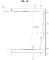
- FIG. 13 is a diagram for describing a process of temporarily assembling the support member to the bottom surface of the storage compartment.
- FIG. 14 is a diagram for describing a process of blowing the foam insulation material into a space between the inner case and the outer case while a jig is inserted into the storage compartment.
- FIG. 15 is a diagram for describing a process of coupling the central rail unit to the support member after blowing the foam insulation material.
- FIG. 16 is a front cross-sectional view of a refrigerator according to another embodiment.
- FIG. 1 is a perspective view of a refrigerator according to an embodiment.
- FIG. 2 is a front cross-sectional view of storage containers and rail units of the refrigerator of FIG. 1 (in which a partition wall 25 is omitted).
- FIG. 3 is a perspective view of a storage container of the refrigerator of FIG. 1 .
- FIG. 4 is a perspective view of a storage container of the refrigerator of FIG. 1 from a different angle.
- FIG. 5 is a front cross-sectional view of a storage container of the refrigerator of FIG. 1 .
- FIG. 6 is a view of rail units separated from an inner case of the refrigerator of FIG. 1 .
- FIG. 7 is a view illustrating rail units installed in the inner case of the refrigerator of FIG. 1 .
- FIG. 8 is a cross-sectional view taken along line I-I of FIG. 7 illustrating a structure in which a side rail unit is fixed to a side surface of a storage compartment by a foam insulation material.
- FIGS. 1 to 8 A refrigerator according to an embodiment is described with reference to FIGS. 1 to 8 .
- a refrigerator 1 includes a main body 10 , storage compartments 21 and 22 formed in the main body 10 to store food, a cool air supply system (not shown) configured to supply cool air to the storage compartments 21 and 22 , and doors 31 , 32 , 33 , and 34 configured to open and close the storage compartments 21 and 22 .
- the storage compartments 21 and 22 may be partitioned into an upper refrigerator compartment 21 to store food in a chilled state and a lower freezer compartment 22 to store food in a frozen state.
- the refrigerator compartment 21 may store food in a chilled state at a temperature of about 0 to about 5° C.
- the freezer compartment 22 may store food in a frozen state at a temperature of about ⁇ 30 to 0° C.
- the refrigerator compartment 21 and the freezer compartment 22 may be separated from each other by a middle wall 24 .
- the freezer compartment 22 may be divided into left and right compartments by a partition wall 25 .
- the partition wall 25 may be integrated with the main body 10 or coupled to the main body 10 as a separate part.
- the aforementioned partitioned structure of the storage compartment is an example, and an exemplary embodiment is not limited thereto.
- the storage compartments 21 and 22 may be opened and closed by the doors 31 , 32 , 33 , and 34 coupled to the main body 10 .
- the refrigerator includes four doors 31 , 32 , 33 , and 34 .
- the refrigerator compartment 21 may be opened and closed by two upper doors 31 and 32
- the freezer compartment 22 may be opened and closed two lower doors 33 and 34 .
- this door structure is an example, and the number and arrangement of doors are not limited thereto.
- the cool air supply system may generate cool air by a refrigeration cycle.
- the cool air supply system may include a compressor (not shown), a condenser (not shown), an expansion device (not shown), an evaporator (not shown), a fan (not shown), and a refrigerant circuit in which a refrigerant is circulated.
- the main body 10 may have an approximate box-shape and an open front.
- the main body 10 includes an inner case 11 , an outer case 18 coupled to outer surfaces of the inner case 11 , and a foam insulation material 19 filled between the inner case 11 and the outer case 18 .
- the inner case 11 may be injection-molded using a resin material.
- the storage compartments 21 and 22 may be formed inside the inner case 11 . That is, the inner case 11 may define ranges of the storage compartments 21 and 22 .
- the inner case 11 of the upper refrigerator compartment 21 has a top side 12 , a bottom side 13 , a left side 14 , a right side 15 , and a rear side 16 surrounding the refrigerator compartment 21 (see, for example, FIGS. 2, 6, and 13 ).
- the top side 12 , the bottom side 13 , the left side 14 , the right side 15 , and the rear side 16 constitute a top surface, a bottom surface, a left surface, a right surface, and a rear surface of the refrigerator compartment 21 , respectively.
- the inner case 11 of the lower freezer compartment 22 has a top side 17 ( FIG. 2 ), a bottom side, a left side, a right side, and a rear side surrounding the freezer compartment 22 .
- the outer case 18 may be formed of a metallic material and define an appearance of the refrigerator 1 .
- the foam insulation material 19 may be blown into a space between the inner case 11 and the outer case 18 .
- the foam insulation material 19 includes urethane foam in which urethane and a blowing agent are mixed.
- the foam insulation material 19 may be filled between the inner case 11 and the outer case 18 after the inner case 11 and the outer case 18 are coupled. Since pressure increasing while blowing the foam insulation material 19 may deform the inner case 11 , a fixing jig 100 (see, for example, FIGS. 13 to 15 ) may be inserted into the inner case 11 to prevent deformation of the inner case 11 while blowing the foam insulation material 19 .
- the foam insulation material 19 having a high adhesive strength may enhance a binding force between the inner case 11 and the outer case 18 . After completion of the blowing process, the foam insulation material 19 may have a sufficient strength.
- the foam insulation material 19 may fix a side rail unit 70 and a support member 90 to the left and right sides 14 and 15 and the bottom side 13 of the inner case 11 .
- a vacuum insulation panel may be disposed between the inner case 11 and the outer case 18 in addition to the foam insulation material 19 .
- Shelves 35 on which food is placed may be arranged in the storage compartment 21 .
- the storage containers 41 , 42 , and 43 to accommodate food may be arranged in the storage compartment 21 .
- the storage containers 41 , 42 , and 43 may slide into and out of the storage compartment 21 .
- the storage containers 41 , 42 , and 43 may be arranged in a horizontal direction.
- the storage container 41 includes a body 50 having a storage space 56 and guide units 58 disposed at a right side and a left side of the body 50 of the storage container 41 .
- the body 50 may have a front wall 51 , a rear wall 52 , a left wall 53 , a right wall 54 , and a bottom wall 55 .
- the storage container 41 may have an open top. Food may be put into and taken out of the storage space 56 through the open top.
- the storage container 41 may also include a cover (not shown) coupled to the body 50 to open and close the open top, thereby store food in a sealed state.
- the left wall 53 and the right wall 54 may be inclined such that an upper width of the storage container 41 is greater than a lower width. Thus, food may be easily put into and taken out of the storage container 41 .
- the guide units 58 (see, for example, FIG. 4 ) to guide movement of the storage container 41 may be installed at lower ends of the left wall 53 and the right wall 54 .
- the guide units 58 may be supported by rail units 70 and 80 .
- the guide units 58 may include guide bars 59 protruding from the lower ends of the left wall 53 and the right wall 54 , respectively and extending in a forward-backward direction.
- the guide bar 59 may be accommodated in guide bar accommodation units 72 and 82 of the rail units 70 and 80 , which will be described later. Bottom surfaces of the guide bars 59 may be supported by rail rollers 74 and 84 of the rail units 70 and 80 .
- the guide units 58 may include guide rollers 60 disposed behind the guide bars 59 .
- the guide roller 60 may move on roller support surfaces 73 and 83 of the rail units 70 and 80 .
- the storage container 41 may smoothly slide into and out of the storage compartment 21 in the forward-backward direction by interaction between the guide units 58 and the rail units 70 and 80 .
- the structure in which the guide units 58 are disposed at the lower ends of the left wall 53 and the right wall 54 may reduce a wasted space of the storage space of the storage compartment 21 in comparison with a structure in which guide units are disposed at upper ends of the left wall 53 and the right wall 54 .
- the refrigerator 1 includes the rail units 70 and 80 installed in the storage compartment 21 to support the storage containers 41 , 42 , and 43 and guide movement of the storage containers 41 , 42 , and 43 .
- the rail units 70 and 80 include side rail units 70 installed at both side surfaces of the storage compartment 21 and central rail units 80 installed at the bottom surface of the storage compartment 21 .
- three storage containers 41 , 42 , and 43 , a pair of the side rail units 70 , and a pair of the central rail units 80 may be provided.
- the storage container 41 may be supported by a left side rail unit 70 and a left central rail unit 80
- the storage container 42 may be supported by a left central rail unit 80 and a right central rail unit 80
- the storage container 43 may be supported by a right central rail unit 80 and a right side rail unit 70 .
- the numbers of the storage containers 41 , 42 , and 43 and the rail units 70 and 80 are not limited thereto (see, for example, FIG. 16 ).
- the side rail units 70 may be coupled to side surfaces of the storage compartment 21 . That is, the side rail units 70 may be coupled to the left side 14 and the right side 15 of the inner case 11 .
- the left side 14 and the right side 15 of the inner case 11 respectively may have side coupling holes 14 a and 15 a (see, for example, FIG. 6 ) and the side rail units 70 have side coupling protrusions 75 .
- a plurality of side coupling protrusions 75 may be provided, and some of the side coupling protrusions 75 may have a hook or clamp shape. Thus, as the side coupling protrusions 75 are inserted into the side coupling holes 14 a and 15 a and slide thereinto, the side rail units 70 are temporarily assembled to the left and right sides 14 and 15 of the inner case 11 .
- the foam insulation material 19 By blowing the foam insulation material 19 into a space between the inner case 11 and the outer case 18 in a state that the side rail units 70 are temporarily assembled to the inner case 11 , the foam insulation material 19 may surround and support the side coupling protrusions 75 . Thus, the side rail units 70 may be fixed to the inner case 11 .
- the side rail unit 70 may include a rail body 71 , a guide bar accommodation unit 72 extending in the forward-backward direction to accommodate the guide bar 59 of the storage container 41 , a roller support surface 73 to support the guide roller 60 of the storage container 41 , and a rail roller 74 disposed in front of the guide bar accommodation unit 72 to support the bottom surface of the guide bar 59 of the storage container 41 .
- FIG. 9 is a view illustrating a state in which a support member is coupled to the bottom surface of the storage compartment of the refrigerator of FIG. 1 .
- FIG. 10 is a cross-sectional view taken along line II-II of FIG. 9 illustrating a structure in which the support member is fixed to the bottom surface of the storage compartment by the foam insulation material.
- FIG. 11 is a view illustrating a state in which a central rail unit is coupled to the support member of the refrigerator of FIG. 1 .
- FIG. 12 is a cross-sectional view taken along line III-III of FIG. 11 illustrating a structure in which an insertion protrusion of the central rail unit is inserted into an insertion groove of the support member.
- the central rail units 80 and the support member 90 of the refrigerator according to an embodiment are described with reference to FIGS. 9 to 11 .
- the central rail units 80 are installed at the bottom surface of the storage compartment 21 . That is, the central rail units 80 are installed at the bottom side 13 of the inner case 11 .
- the support member 90 may be disposed between the central rail units 80 and the bottom side 13 of the inner case 11 to stably support the central rail units 80 .
- the support member 90 may be coupled to the bottom side 13 of the inner case 11 and the central rail units 80 may be coupled to the support member 90 .
- the bottom side 13 of the inner case 11 may be provided with a support member coupling unit 13 b.
- the support member 90 may include a base 91 having a panel shape and disposed in a close contact with the bottom side 13 of the inner case 11 and bottom coupling protrusions 92 protruding downward from the base 91 to be supported by the foam insulation material 19 in a contact state therewith.
- the bottom coupling protrusion 92 may pass through the bottom side 13 of the inner case 11 .
- the bottom side 13 of the inner case 11 may have a bottom coupling hole 13 a .
- the bottom coupling protrusion 92 may pass thought the bottom coupling hole 13 a and protrude from the bottom side 13 of the inner case 11 downward.
- a plurality of bottom coupling protrusions 92 may be formed, and some of the bottom coupling protrusions 92 may have a hook or clamp shape. Thus, as the bottom coupling protrusions 92 are inserted into the bottom coupling holes 13 a and slide thereinto, the support member 90 may be temporarily assembled to the bottom side 13 of the inner case 11 .
- the foam insulation material 19 By blowing the foam insulation material 19 into a space between the inner case 11 and the outer case 18 in a state that the support member 90 is temporarily assembled to the inner case 11 , the foam insulation material 19 may surround and support the bottom coupling protrusions 92 . Thus, the support member 90 may be fixed.
- the central rail units 80 may be coupled to the support member 90 .
- the central rail units 80 may be coupled to the support member 90 by press fit. That is, the central rail units 80 may be coupled to the support member 90 by inserting portions of the central rail units 80 into the support member 90 by sliding.
- the central rail units 80 include insertion protrusions 85 disposed at lower portions of the rail bodies 81 , and the support member 90 includes hook portions 93 constituting insertion grooves 94 into which the insertion protrusions 85 are inserted (see, for example, FIG. 12 ).
- the hook portions 93 protrude upward from the base 91 and have a hook or clamp shape such that the insertion grooves 94 are formed between the hook portions 93 and the base 91 .
- the hook portions 93 may be elastically deformed. Thus, as the insertion protrusions 85 are inserted into the insertion grooves 94 , the hook portions 93 are slightly spread accumulating elasticity. The accumulated elastic force presses the insertion protrusions 85 such that coupling between the central rail units 80 and the support member 90 may be maintained. However, if the rail units are pulled with a force greater than the elasticity, the central rail units 80 may be separated from the support member 90 .
- a coupling structure of the bottom side 13 of the inner case 11 and the support member 90 and a coupling structure of the support member 90 and the central rail units 80 do not require a separate coupling member since the foam insulation material 19 and structures thereof are used for the coupling processes. Thus, coupling thereof may be simply performed using a reduced number of parts.
- the central rail unit 80 may include a rail body 81 , a guide bar accommodation unit 82 extending in the forward-backward direction to accommodate the guide bar 59 of the storage container 41 , a roller support surface 83 to support the guide roller 60 of the storage container 41 , and a rail roller 84 disposed in front of the guide bar accommodation unit 82 to support the guide bar 59 of the storage container 41 .
- a pair of each of the guide bar accommodation units 82 , the roller support surfaces 83 , and the rail rollers 84 may be disposed at left and right sides of the central rail unit 80 , which is different from the side rail unit 70 .
- FIGS. 13 to 15 are diagrams for describing an installation process of a central rail unit of the refrigerator of FIG. 1 .
- FIG. 13 is a diagram for describing a process of temporarily assembling the support member to the bottom surface of the storage compartment.
- FIG. 14 is a diagram for describing a process of blowing the foam insulation material into a space between the inner case and the outer case while a jig is inserted into the storage compartment.
- FIG. 15 is a diagram for describing a process of coupling the central rail unit to the support member after blowing the foam insulation material.
- the support member 90 is temporarily assembled to the bottom side 13 of the inner case 11 .
- the support member 90 may be temporarily assembled to the bottom side 13 of the inner case 11 by inserting the bottom coupling protrusions 92 of the support member 90 into the bottom coupling holes 13 a of the bottom side 13 of the inner case 11 and sliding thereinto.
- the side rail units 70 may also be temporarily assembled to the left and right sides 14 and 15 of the inner case 11 .
- the side rail units 70 may be temporarily assembled to the left and right sides 14 and 15 of the inner case 11 by inserting the side coupling protrusions 75 of the side rail units 70 into the side coupling holes 14 a and 15 a of the left and right sides 14 and 15 of the inner case 11 and sliding thereinto.
- the fixing jig 100 is inserted into the storage compartment 21 to prevent deformation of the inner case 11 by a pressure increasing while blowing the foam insulation material 19 or prevent separation of the support member 90 and the side rail unit 70 temporarily assembled to the inner case 11 from the inner case 11 .
- the foam insulation material 19 is blown into the space between the inner case 11 and the outer case 18 as illustrated in FIG. 14 .
- the fixing jig 100 may be inserted to be close to the bottom side 13 of the inner case 11 as illustrated in FIG. 14 .
- the fixing jig 100 may efficiently prevent deformation of the bottom side 13 of the inner case 11 while blowing the foam insulation material 19 .
- the fixing jig 100 should be spaced apart from the bottom side 13 of the inner case 11 by a height of the central rail units 80 to prevent interference between the central rail units 80 and the fixing jig 100 while inserting the fixing jig 100 . In this case, deformation of the bottom side 13 of the inner case 11 may not be efficiently prevented.
- the fixing jig 100 may be removed from the storage compartment 21 and the central rail units 80 may be coupled to the support member 90 as illustrated in FIG. 15 .
- the central rail units 80 may be coupled to the support member 90 by inserting the insertion protrusions 85 of the central rail units 80 into the insertion groove 94 of the support member 90 by press fit.
- FIG. 16 is a front cross-sectional view of a refrigerator according to another embodiment.
- FIG. 16 An exemplary embodiment of a refrigerator is described with reference to FIG. 16 .
- the same reference numerals are used to the same elements described above, and descriptions thereof may not be repeated.
- a refrigerator 200 may have two storage containers 241 and 242 which is different from the aforementioned embodiment.
- a pair of side rail units 270 and a central rail unit 280 may be provided in a storage compartment to support storage containers 241 and 242 and guide movement thereof.
- a left side rail unit 270 may be installed at the left side 14 of the inner case 11
- a right side rail unit 270 may be installed at the right side 15 of the inner case 11
- the central rail unit 280 may be installed at the bottom side 13 of the inner case 11 .
- the support member 90 which is coupled to the bottom side 13 of the inner case 11 to support the central rail unit 280 , may be disposed between the central rail unit 280 and the bottom side 13 of the inner case 11 .
- the support member 90 may be fixed by the foam insulation material 19 blown into the space between the inner case 11 and the outer case 18 .
- the central rail unit 280 and the support member 90 may be coupled by press fit without using a separate coupling member.
- roller units are installed at the bottom surface of the storage compartment by using the foam insulation material blown into the space between the inner case and the outer case and the coupling structure of the roller unit without using a separate coupling member, a process of assembling the refrigerator may be easily performed.
Landscapes
- Engineering & Computer Science (AREA)
- Chemical & Material Sciences (AREA)
- Combustion & Propulsion (AREA)
- Physics & Mathematics (AREA)
- Mechanical Engineering (AREA)
- Thermal Sciences (AREA)
- General Engineering & Computer Science (AREA)
- Refrigerator Housings (AREA)
- Devices That Are Associated With Refrigeration Equipment (AREA)
Abstract
Description
Claims (10)
Applications Claiming Priority (2)
| Application Number | Priority Date | Filing Date | Title |
|---|---|---|---|
| KR10-2015-0171940 | 2015-12-04 | ||
| KR1020150171940A KR102447914B1 (en) | 2015-12-04 | 2015-12-04 | refrigerator |
Publications (2)
| Publication Number | Publication Date |
|---|---|
| US20170160002A1 US20170160002A1 (en) | 2017-06-08 |
| US10591203B2 true US10591203B2 (en) | 2020-03-17 |
Family
ID=57482270
Family Applications (1)
| Application Number | Title | Priority Date | Filing Date |
|---|---|---|---|
| US15/367,747 Active US10591203B2 (en) | 2015-12-04 | 2016-12-02 | Refrigerator |
Country Status (4)
| Country | Link |
|---|---|
| US (1) | US10591203B2 (en) |
| EP (1) | EP3176525B1 (en) |
| KR (1) | KR102447914B1 (en) |
| CN (1) | CN106839583B (en) |
Cited By (2)
| Publication number | Priority date | Publication date | Assignee | Title |
|---|---|---|---|---|
| US11464332B2 (en) * | 2018-12-21 | 2022-10-11 | Lg Electronics Inc. | Refrigerator |
| US12152831B2 (en) | 2021-04-06 | 2024-11-26 | Electrolux Home Products, Inc. | Crisper assembly with slide out shelf |
Families Citing this family (10)
| Publication number | Priority date | Publication date | Assignee | Title |
|---|---|---|---|---|
| KR102373219B1 (en) * | 2015-12-10 | 2022-03-17 | 삼성전자주식회사 | Refrigerator |
| CN107218766B (en) * | 2017-06-14 | 2019-09-17 | 合肥华凌股份有限公司 | Three drawer leveling structures and the refrigerator with the structure |
| US10088224B1 (en) * | 2017-07-26 | 2018-10-02 | Haier Us Appliance Solutions, Inc. | Refrigerator appliance having multiple chilled chambers |
| US10317127B2 (en) * | 2017-09-27 | 2019-06-11 | Haier Us Appliance Solutions, Inc. | Refrigerator appliances including a drawer assembly |
| US10371436B2 (en) * | 2017-11-08 | 2019-08-06 | Whirlpool Corporation | Bin assembly |
| KR102559744B1 (en) * | 2018-06-20 | 2023-07-28 | 삼성전자주식회사 | Refrigerator |
| KR20230013479A (en) * | 2021-07-19 | 2023-01-26 | 삼성전자주식회사 | Refrigerator |
| CN116067063B (en) * | 2021-11-02 | 2025-08-22 | 海信容声(广东)冰箱有限公司 | A refrigerator |
| CN116136346A (en) * | 2021-11-17 | 2023-05-19 | 博西华家用电器有限公司 | A kind of refrigeration appliance and its manufacturing method |
| KR20230108543A (en) * | 2022-01-11 | 2023-07-18 | 엘지전자 주식회사 | Portable refrigerator and main refrigerator having the same |
Citations (10)
| Publication number | Priority date | Publication date | Assignee | Title |
|---|---|---|---|---|
| US2490494A (en) * | 1947-04-11 | 1949-12-06 | Erwin R Widman | Refrigerator cabinet |
| JPH0527588A (en) | 1991-07-19 | 1993-02-05 | Fujitsu Ltd | Developing device for electrophotographic device |
| JPH10300334A (en) | 1997-04-23 | 1998-11-13 | Matsushita Refrig Co Ltd | Refrigerator |
| US5918959A (en) * | 1996-12-30 | 1999-07-06 | Daewoo Electronics Co., Ltd. | Foodstuff storing device for a refrigerator |
| CN101171489A (en) | 2005-05-10 | 2008-04-30 | Bsh博世和西门子家用器具有限公司 | Refrigerator with refrigerated goods container that can be telescopically guided |
| US20090223242A1 (en) | 2008-03-06 | 2009-09-10 | Samsung Electronics Co., Ltd. | Refrigerator with receiving box |
| US20110127896A1 (en) | 2009-11-30 | 2011-06-02 | Whirlpool Corporation | Universal crisper frame able to accommodate a variety of crisper configurations |
| WO2013042338A2 (en) | 2011-09-22 | 2013-03-28 | Panasonic Corporation | Refrigerator |
| EP2682698A1 (en) | 2011-03-02 | 2014-01-08 | Panasonic Corporation | Refrigerator |
| US20140265801A1 (en) * | 2013-03-15 | 2014-09-18 | Whirlpool Corporation | Slide assembly for refrigerator storage drawer |
Family Cites Families (3)
| Publication number | Priority date | Publication date | Assignee | Title |
|---|---|---|---|---|
| JP2522096Y2 (en) * | 1991-09-20 | 1997-01-08 | 三菱電機株式会社 | refrigerator |
| KR100495628B1 (en) * | 2003-06-27 | 2005-06-16 | 삼성전자주식회사 | Refrigerator |
| KR101219433B1 (en) * | 2005-01-11 | 2013-01-11 | 삼성전자주식회사 | Refrigerator |
-
2015
- 2015-12-04 KR KR1020150171940A patent/KR102447914B1/en active Active
-
2016
- 2016-12-02 EP EP16202015.0A patent/EP3176525B1/en active Active
- 2016-12-02 CN CN201611101495.2A patent/CN106839583B/en active Active
- 2016-12-02 US US15/367,747 patent/US10591203B2/en active Active
Patent Citations (13)
| Publication number | Priority date | Publication date | Assignee | Title |
|---|---|---|---|---|
| US2490494A (en) * | 1947-04-11 | 1949-12-06 | Erwin R Widman | Refrigerator cabinet |
| JPH0527588A (en) | 1991-07-19 | 1993-02-05 | Fujitsu Ltd | Developing device for electrophotographic device |
| US5918959A (en) * | 1996-12-30 | 1999-07-06 | Daewoo Electronics Co., Ltd. | Foodstuff storing device for a refrigerator |
| JPH10300334A (en) | 1997-04-23 | 1998-11-13 | Matsushita Refrig Co Ltd | Refrigerator |
| US8398187B2 (en) * | 2005-05-10 | 2013-03-19 | Bsh Bosch Und Siemens Hausgeraete Gmbh | Refrigerator comprising an extractably guided receptacle for chilled goods |
| CN101171489A (en) | 2005-05-10 | 2008-04-30 | Bsh博世和西门子家用器具有限公司 | Refrigerator with refrigerated goods container that can be telescopically guided |
| US20090056365A1 (en) | 2005-05-10 | 2009-03-05 | BSH Bosch und Siemens Hausgeräte GmbH | Refrigerator Comprising an Extractably Guided Receptacle for Chilled Goods |
| US20090223242A1 (en) | 2008-03-06 | 2009-09-10 | Samsung Electronics Co., Ltd. | Refrigerator with receiving box |
| US20110127896A1 (en) | 2009-11-30 | 2011-06-02 | Whirlpool Corporation | Universal crisper frame able to accommodate a variety of crisper configurations |
| EP2682698A1 (en) | 2011-03-02 | 2014-01-08 | Panasonic Corporation | Refrigerator |
| WO2013042338A2 (en) | 2011-09-22 | 2013-03-28 | Panasonic Corporation | Refrigerator |
| CN103827611A (en) | 2011-09-22 | 2014-05-28 | 松下电器产业株式会社 | Refrigerator |
| US20140265801A1 (en) * | 2013-03-15 | 2014-09-18 | Whirlpool Corporation | Slide assembly for refrigerator storage drawer |
Non-Patent Citations (5)
| Title |
|---|
| Chinese Office Action dated Jul. 11, 2019 in related Chinese Application No. 201611101495.2 with English translation (16 pages). |
| Chinese Office Action dated Nov. 2, 2018 in Chinese Patent Application No. 201611101495.2. |
| European Communication dated Jan. 25, 2019 in European Patent Application No. 16 202 015.0 (6 pages). |
| European Communication dated Jun. 12, 2018 in European Patent Application No. 16202015.0. |
| Extended European Search Report dated Apr. 3, 2017 in corresponding European Patent Application No. 16 20 2015. |
Cited By (2)
| Publication number | Priority date | Publication date | Assignee | Title |
|---|---|---|---|---|
| US11464332B2 (en) * | 2018-12-21 | 2022-10-11 | Lg Electronics Inc. | Refrigerator |
| US12152831B2 (en) | 2021-04-06 | 2024-11-26 | Electrolux Home Products, Inc. | Crisper assembly with slide out shelf |
Also Published As
| Publication number | Publication date |
|---|---|
| CN106839583A (en) | 2017-06-13 |
| US20170160002A1 (en) | 2017-06-08 |
| KR102447914B1 (en) | 2022-09-28 |
| EP3176525B1 (en) | 2020-08-05 |
| KR20170065775A (en) | 2017-06-14 |
| EP3176525A1 (en) | 2017-06-07 |
| CN106839583B (en) | 2020-03-06 |
Similar Documents
| Publication | Publication Date | Title |
|---|---|---|
| US10591203B2 (en) | Refrigerator | |
| US9677807B2 (en) | Refrigerator | |
| EP2818814B1 (en) | Refrigerator | |
| US8911040B2 (en) | Refrigerator | |
| KR101622008B1 (en) | Sealing structure of a central wall for refrigrator and refrigrator having the same | |
| US20100090574A1 (en) | Refrigerator | |
| US10197327B2 (en) | Refrigerator and basket assembly thereof | |
| US20180087828A1 (en) | Refrigerator | |
| US10648726B2 (en) | Refrigerator | |
| US20170292777A1 (en) | Refrigerator and drawer assembly thereof | |
| KR20090121030A (en) | Refrigerator with sliding shelf | |
| US20170292778A1 (en) | Refrigerator and drawer assembly thereof | |
| KR20180066497A (en) | Refrigerator | |
| JP2016118313A (en) | refrigerator | |
| US20240159457A1 (en) | Refrigerator | |
| US12398948B2 (en) | Refrigerator | |
| JP5917115B2 (en) | Insulation cabinet | |
| JP2023099222A (en) | refrigerator | |
| KR100965358B1 (en) | Refrigerator | |
| KR20100025139A (en) | A refrigerator | |
| KR101481525B1 (en) | Stand type refrigerator | |
| JP2016075421A (en) | refrigerator | |
| KR20230132219A (en) | Refrigerator | |
| KR20230038047A (en) | Refrigerator | |
| KR20150045750A (en) | Refrigerator |
Legal Events
| Date | Code | Title | Description |
|---|---|---|---|
| AS | Assignment |
Owner name: SAMSUNG ELECTRONICS CO., LTD., KOREA, REPUBLIC OF Free format text: ASSIGNMENT OF ASSIGNORS INTEREST;ASSIGNORS:KANG, BYEONG KOOK;PARK, JONG SUN;CHO, BYOUNG-JAE;REEL/FRAME:040519/0475 Effective date: 20161203 |
|
| STPP | Information on status: patent application and granting procedure in general |
Free format text: NON FINAL ACTION MAILED |
|
| STPP | Information on status: patent application and granting procedure in general |
Free format text: RESPONSE TO NON-FINAL OFFICE ACTION ENTERED AND FORWARDED TO EXAMINER |
|
| STPP | Information on status: patent application and granting procedure in general |
Free format text: FINAL REJECTION MAILED |
|
| STPP | Information on status: patent application and granting procedure in general |
Free format text: RESPONSE AFTER FINAL ACTION FORWARDED TO EXAMINER |
|
| STPP | Information on status: patent application and granting procedure in general |
Free format text: ADVISORY ACTION MAILED |
|
| STPP | Information on status: patent application and granting procedure in general |
Free format text: DOCKETED NEW CASE - READY FOR EXAMINATION |
|
| STPP | Information on status: patent application and granting procedure in general |
Free format text: NOTICE OF ALLOWANCE MAILED -- APPLICATION RECEIVED IN OFFICE OF PUBLICATIONS |
|
| STPP | Information on status: patent application and granting procedure in general |
Free format text: PUBLICATIONS -- ISSUE FEE PAYMENT VERIFIED |
|
| STCF | Information on status: patent grant |
Free format text: PATENTED CASE |
|
| MAFP | Maintenance fee payment |
Free format text: PAYMENT OF MAINTENANCE FEE, 4TH YEAR, LARGE ENTITY (ORIGINAL EVENT CODE: M1551); ENTITY STATUS OF PATENT OWNER: LARGE ENTITY Year of fee payment: 4 |