US1059120A - Spark-coil. - Google Patents
Spark-coil. Download PDFInfo
- Publication number
- US1059120A US1059120A US67342312A US1912673423A US1059120A US 1059120 A US1059120 A US 1059120A US 67342312 A US67342312 A US 67342312A US 1912673423 A US1912673423 A US 1912673423A US 1059120 A US1059120 A US 1059120A
- Authority
- US
- United States
- Prior art keywords
- coil
- blocks
- spark
- bolt
- block
- Prior art date
- Legal status (The legal status is an assumption and is not a legal conclusion. Google has not performed a legal analysis and makes no representation as to the accuracy of the status listed.)
- Expired - Lifetime
Links
- 239000011810 insulating material Substances 0.000 description 3
- 239000002184 metal Substances 0.000 description 3
- 229910052751 metal Inorganic materials 0.000 description 3
- XEEYBQQBJWHFJM-UHFFFAOYSA-N Iron Chemical compound [Fe] XEEYBQQBJWHFJM-UHFFFAOYSA-N 0.000 description 2
- 208000027418 Wounds and injury Diseases 0.000 description 2
- 238000010276 construction Methods 0.000 description 2
- 229910001018 Cast iron Inorganic materials 0.000 description 1
- 229920000742 Cotton Polymers 0.000 description 1
- 241000219146 Gossypium Species 0.000 description 1
- 239000004020 conductor Substances 0.000 description 1
- 230000006378 damage Effects 0.000 description 1
- 210000005069 ears Anatomy 0.000 description 1
- 208000014674 injury Diseases 0.000 description 1
- 229910052742 iron Inorganic materials 0.000 description 1
- 239000000463 material Substances 0.000 description 1
Images
Classifications
-
- H—ELECTRICITY
- H01—ELECTRIC ELEMENTS
- H01F—MAGNETS; INDUCTANCES; TRANSFORMERS; SELECTION OF MATERIALS FOR THEIR MAGNETIC PROPERTIES
- H01F27/00—Details of transformers or inductances, in general
- H01F27/28—Coils; Windings; Conductive connections
- H01F27/29—Terminals; Tapping arrangements for signal inductances
- H01F27/292—Surface mounted devices
Definitions
- the bolt 19 takes the' form of a rivet, and is headed up at one end against onev o' the blocks,'as 15, but pro'ects' a sufficient distance beyond the outer ace of the other block to receive Aan insulating washer ⁇ 21 and a metal Washer 22 against xwhich end isupset.
- a binding-post 23 is set into the block 16, Which is -insulated from the bolt 19, and to it is attachedone line of anelectric circuit, and a binding post 24 may be set in theen of the central boltthus ⁇ electrically connecting it'with the other block of the magnetic circuit, the other branch 28 of the electric To all whom t may concern:
- the invention is exempli fiedin the structure hereinafter described, and.l which is in which circuit being attached to this post.
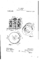
- Figure 1 is a plan view of the device; Fig.
- a 2 When it is desired to secure the coil to a 2 is a sectional view on the'A line 2-2 o support 'it may be provided with a bracketl plate 25, which is conveniently secured to it by being held under one of theA headed ends of the bolt 19, as shown, this bracket plate being provided with a suitable number of apertured ears, as 26, through which screws may be passed.
- the return circuit may, of course, through the Fig. 1; and
- Fig. 3 is a detail'in perspective of the spool for carrying the coil and shows the manner of attachiig the ends of the coil.
- the coil 10 is forme spool comprising a 11, 12, ⁇ Which are prete. form, each being a flat annulus having a central upstandin flan e 13, these flanges, entering the .ends o a tu wire ⁇ Wound upon a '11i which may be and preferably is of strawcase a binding post 24 is not required.
- Cur ⁇ board or similar material
- One terminal of rent being led to the .block 16 through the the coil 10 is in electrical contactand prefbinding post 23, enters the coil through the erably soldered to one of the 'annularplates i as 12, the other terminal of the coil being passing through the block 15 to lthe'ground similarly connected with the other plate, as or to the return side of the line 'which will 11. -These connections may, if desired, be attached to the binding post, 24. y made in the manner shown at 10l and 10", Any interrupt-ion of the current, as by the ordinary operation of the makeA and break igniting device of respectively, Fig. 3.
- the magnetic circuit consists of a pair of similar soft iron blocks 15, 16, each having' formed in one of its faces an annular channel or receiving one end ofthe coil and its These two blocks are spaced apart by an annulus 17 of non-conducting material, Which encircles the coil, leaving an air gap 'between the adjacent facesv of the blocks, as shown at 18.
- the two blocks 15, 16 are centrally apertured to receive a bolt or rivet 19 by which they are high voltage to insure an igniting spark.
- The. blocks 15, 16, are of cast iron'and require very litt-le machine Work, it being Anecessary only to drill or ream o-ut the central. apertures and drill and tap the aper; ture for receiving the binding post 23.
- one of the blocks, as 15, is substantially the I claim as my inventionsame as the diameter of he bolt, so that the 1.
- a spark coil in combination, a coil, a pair of electrically insulated magnet blocks inter makes an electrical contact with the block. rl ⁇ he cen/tra), aperture in the other apeitured to receive the ends of the coil and and leaves it through the plate 11,.y
- the parts are all simple and 'cheap of construction and easily assembled, and when 'each being and binding posts connected with tlie respective blocks.
- the coil is Wound and.
- a pair of annular plates enen aving a central instanding litiange, and a tube o insulating material fitted upon the flanges of the two plates, the terminals of the coil being electricallyconnected with the annular plates; a pair of magnet blocks aperturcd to receive the ends of the coil, such blocks being electrically insulated each but connected With the rethe coil, the two blocks together and being in electrical contact with one of such blocks and insulated from the otlieiya binding post set in one of the blocks, and a binding post set;
Landscapes
- Engineering & Computer Science (AREA)
- Power Engineering (AREA)
- Ignition Installations For Internal Combustion Engines (AREA)
Description
W. H. COTTON. SPARK con..
' APPLICATION PILBDJALM. 1912.
1,059,120.` v I PatentedApr.1,1913.
I Va'citizen of the United States,
' of metal stampings erably identical in supporting spool.
.illustrated in the accompanying drawings,
' secured together.
ASSIG'NOR OF FIFTY-ONE ONE- OF CHICAGO, ILLINOIS.
SPARK-corn.
Speciilcation of Letters Patent. Patented AIMA-15, 1913.
1,059,120. Application led January 2.5, 1912. I Serial No. 673,423.
block, as `16 is'oi somewhat greater diameter than the bolt, and is lined with a Isleeve 20 of insulating material. Preferably, and as shown, the bolt 19 takes the' form of a rivet, and is headed up at one end against onev o' the blocks,'as 15, but pro'ects' a sufficient distance beyond the outer ace of the other block to receive Aan insulating washer` 21 and a metal Washer 22 against xwhich end isupset. f v A binding-post 23 is set into the block 16, Which is -insulated from the bolt 19, and to it is attachedone line of anelectric circuit, and a binding post 24 may be set in theen of the central boltthus `electrically connecting it'with the other block of the magnetic circuit, the other branch 28 of the electric To all whom t may concern:
Be it known that I, WALTER H. Coi'roN, and, resident of Chicago, county of Cook, and State of Illinois, have inventedcertain new an luseful Improvements in Spark-Coils, of which the following is a specification, and which are illustrated in the accom anying draw' in, forming ya part thereo he invention relates to spark coils .especially ada ted for use in igniting gas engines. ts object is to provide a coil which, While hihl eiiicient, is very compact, simple, an c eap of construction.
The invention is exempli fiedin the structure hereinafter described, and.l which is in which circuit being attached to this post.
Figure 1 is a plan view of the device; Fig. When it is desired to secure the coil to a 2 is a sectional view on the'A line 2-2 o support 'it may be provided with a bracketl plate 25, which is conveniently secured to it by being held under one of theA headed ends of the bolt 19, as shown, this bracket plate being provided with a suitable number of apertured ears, as 26, through which screws may be passed. When the coil is attached to a metal support, as to the cylinder of an engine, the return circuit may, of course, through the Fig. 1; and Fig. 3 is a detail'in perspective of the spool for carrying the coil and shows the manner of attachiig the ends of the coil.
The coil 10 is forme spool comprising a 11, 12,`Which are prete. form, each being a flat annulus having a central upstandin flan e 13, these flanges, entering the .ends o a tu wire `Wound upon a '11i which may be and preferably is of strawcase a binding post 24 is not required. Cur` board or similar material. One terminal of rent being led to the .block 16 through the the coil 10 is in electrical contactand prefbinding post 23, enters the coil through the erably soldered to one of the 'annularplates i as 12, the other terminal of the coil being passing through the block 15 to lthe'ground similarly connected with the other plate, as or to the return side of the line 'which will 11. -These connections may, if desired, be attached to the binding post, 24. y made in the manner shown at 10l and 10", Any interrupt-ion of the current, as by the ordinary operation of the makeA and break igniting device of respectively, Fig. 3.
a gas engine, will The magnetic circuit consists of a pair of similar soft iron blocks 15, 16, each having' formed in one of its faces an annular channel or receiving one end ofthe coil and its These two blocks are spaced apart by an annulus 17 of non-conducting material, Which encircles the coil, leaving an air gap 'between the adjacent facesv of the blocks, as shown at 18. The two blocks 15, 16are centrally apertured to receive a bolt or rivet 19 by which they are high voltage to insure an igniting spark..
The. blocks 15, 16, are of cast iron'and require very litt-le machine Work, it being Anecessary only to drill or ream o-ut the central. apertures and drill and tap the aper; ture for receiving the binding post 23.
assembled are permanently secured so that The diameter of the vcentral aperture in impossible.
one of the blocks, as 15, is substantially the I claim as my inventionsame as the diameter of he bolt, so that the 1. In* a spark coil, in combination, a coil, a pair of electrically insulated magnet blocks inter makes an electrical contact with the block. rl`he cen/tra), aperture in the other apeitured to receive the ends of the coil and and leaves it through the plate 11,.y
develop a countercurrent of the vnecessary disarrangeinent or injury become practically i so engine' as a ground, and in that.
The partsare all simple and 'cheap of construction and easily assembled, and when 'each being and binding posts connected with tlie respective blocks.
ln a spark coil, in comloination,I a coil,
a pair of electrically insulated magnet blocks apertured to receive the endsof the coil' and each being electrically connected therewith,
.and a bolt securing the two magnet blocks annular plates;
the luther, but en together.
3., vIn a spark coil, in combination, a coil; a' spoolnpon which comprising a palr of annular plates each having a central instanding flange, and a tube of insulatingmaterial fitted upon the vlang'es of the two plates, the terminals of the .coil being electrically connected Wit-h the a pair of magnet blocks epertured to receive the ends ofthe-coil, such blocks being electrically insulated each from connected with the respective de of the coil, and means two5 magnet blocks 'togetlieiz ,l in a spark coil, in combination, a coil; a. spool upon which the/coil 4is Wound and electrically connected therewith,
the coil is Wound and.
for binding the comprising a pair of annular plates enen aving a central instanding litiange, and a tube o insulating material fitted upon the flanges of the two plates, the terminals of the coil being electricallyconnected with the annular plates; a pair of magnet blocks aperturcd to receive the ends of the coil, such blocks being electrically insulated each but connected With the rethe coil, the two blocks together and being in electrical contact with one of such blocks and insulated from the otlieiya binding post set in one of the blocks, and a binding post set;
1n the bolt.
WALTER n. COTTON. lWitnesses Lome K. GILLsoN, E. M. KLATCHER.
Priority Applications (1)
| Application Number | Priority Date | Filing Date | Title |
|---|---|---|---|
| US67342312A US1059120A (en) | 1912-01-25 | 1912-01-25 | Spark-coil. |
Applications Claiming Priority (1)
| Application Number | Priority Date | Filing Date | Title |
|---|---|---|---|
| US67342312A US1059120A (en) | 1912-01-25 | 1912-01-25 | Spark-coil. |
Publications (1)
| Publication Number | Publication Date |
|---|---|
| US1059120A true US1059120A (en) | 1913-04-15 |
Family
ID=3127373
Family Applications (1)
| Application Number | Title | Priority Date | Filing Date |
|---|---|---|---|
| US67342312A Expired - Lifetime US1059120A (en) | 1912-01-25 | 1912-01-25 | Spark-coil. |
Country Status (1)
| Country | Link |
|---|---|
| US (1) | US1059120A (en) |
Cited By (5)
| Publication number | Priority date | Publication date | Assignee | Title |
|---|---|---|---|---|
| US2719939A (en) * | 1946-05-22 | 1955-10-04 | Gen Controls Co | Electromagnetic valve |
| US2913640A (en) * | 1957-03-20 | 1959-11-17 | Gen Dynamics Corp | Electromagnetic coil assembly |
| US3105209A (en) * | 1960-11-08 | 1963-09-24 | Allen Bradley Co | Compact circuit |
| US4393364A (en) * | 1980-09-19 | 1983-07-12 | Tdk Electronics Co., Ltd. | Coil element |
| US6163243A (en) * | 1998-06-30 | 2000-12-19 | Siemens Energy & Automation, Inc. | Toroidal current transformer assembly and method |
-
1912
- 1912-01-25 US US67342312A patent/US1059120A/en not_active Expired - Lifetime
Cited By (5)
| Publication number | Priority date | Publication date | Assignee | Title |
|---|---|---|---|---|
| US2719939A (en) * | 1946-05-22 | 1955-10-04 | Gen Controls Co | Electromagnetic valve |
| US2913640A (en) * | 1957-03-20 | 1959-11-17 | Gen Dynamics Corp | Electromagnetic coil assembly |
| US3105209A (en) * | 1960-11-08 | 1963-09-24 | Allen Bradley Co | Compact circuit |
| US4393364A (en) * | 1980-09-19 | 1983-07-12 | Tdk Electronics Co., Ltd. | Coil element |
| US6163243A (en) * | 1998-06-30 | 2000-12-19 | Siemens Energy & Automation, Inc. | Toroidal current transformer assembly and method |
Similar Documents
| Publication | Publication Date | Title |
|---|---|---|
| US217466A (en) | Improvement in electric induction-coils | |
| US3660790A (en) | Electrical inductive/capacitive component | |
| US1629132A (en) | Electric jump-spark coil | |
| US2614232A (en) | Air gap construction | |
| US2531638A (en) | Ignition circuit | |
| US1546855A (en) | Stationary induction apparatus | |
| US952692A (en) | Spark-coil. | |
| US1644332A (en) | Frequency transformer | |
| US1307867A (en) | Eable p | |
| US1486648A (en) | Induction coll | |
| US1132297A (en) | Electrical equipment for internal-combustion engines. | |
| US3344383A (en) | Core portions having fused bond joint outside of embrace of coils thereon | |
| US1223947A (en) | Induction-coil. | |
| US1599842A (en) | Ignition coil | |
| US1303162A (en) | Spark-coil | |
| US1533797A (en) | Induction coil | |
| US1312497A (en) | Transpormer-coil por ignition | |
| US1569756A (en) | Ignition coil | |
| US1508622A (en) | Spark-amplifying device | |
| US933622A (en) | Electrical cooking apparatus. | |
| US2548210A (en) | Electrical coil | |
| US1227038A (en) | Resistance unit for electric circuits. | |
| US672989A (en) | Transformer. | |
| US1220508A (en) | Electric heater. | |
| US1066293A (en) | Alternating-current electromagnet. |