US1059064A - Mechanical toy. - Google Patents
Mechanical toy. Download PDFInfo
- Publication number
- US1059064A US1059064A US73285512A US1912732855A US1059064A US 1059064 A US1059064 A US 1059064A US 73285512 A US73285512 A US 73285512A US 1912732855 A US1912732855 A US 1912732855A US 1059064 A US1059064 A US 1059064A
- Authority
- US
- United States
- Prior art keywords
- track
- truck
- supplemental
- main
- hopper
- Prior art date
- Legal status (The legal status is an assumption and is not a legal conclusion. Google has not performed a legal analysis and makes no representation as to the accuracy of the status listed.)
- Expired - Lifetime
Links
- 230000000153 supplemental effect Effects 0.000 description 86
- 230000000994 depressogenic effect Effects 0.000 description 9
- 210000002105 tongue Anatomy 0.000 description 8
- 238000010276 construction Methods 0.000 description 6
- 230000005484 gravity Effects 0.000 description 3
- 239000002184 metal Substances 0.000 description 2
- 239000000126 substance Substances 0.000 description 2
- 230000009191 jumping Effects 0.000 description 1
- 230000004048 modification Effects 0.000 description 1
- 238000012986 modification Methods 0.000 description 1
- 229920000136 polysorbate Polymers 0.000 description 1
- 230000000284 resting effect Effects 0.000 description 1
- 239000004576 sand Substances 0.000 description 1
Images


Classifications
-
- B—PERFORMING OPERATIONS; TRANSPORTING
- B65—CONVEYING; PACKING; STORING; HANDLING THIN OR FILAMENTARY MATERIAL
- B65G—TRANSPORT OR STORAGE DEVICES, e.g. CONVEYORS FOR LOADING OR TIPPING, SHOP CONVEYOR SYSTEMS OR PNEUMATIC TUBE CONVEYORS
- B65G67/00—Loading or unloading vehicles
-
- Y—GENERAL TAGGING OF NEW TECHNOLOGICAL DEVELOPMENTS; GENERAL TAGGING OF CROSS-SECTIONAL TECHNOLOGIES SPANNING OVER SEVERAL SECTIONS OF THE IPC; TECHNICAL SUBJECTS COVERED BY FORMER USPC CROSS-REFERENCE ART COLLECTIONS [XRACs] AND DIGESTS
- Y10—TECHNICAL SUBJECTS COVERED BY FORMER USPC
- Y10S—TECHNICAL SUBJECTS COVERED BY FORMER USPC CROSS-REFERENCE ART COLLECTIONS [XRACs] AND DIGESTS
- Y10S414/00—Material or article handling
- Y10S414/128—Handler-type toys
Definitions
- This invention relates to mechanical toys, and the object thereof is to produce an improved device or apparatus of this class the manipulation of which will entertain and amuseboth young and old, and with this and other objects in view, the invention consists in a device or apparatus of the class specified, constructed and operated as her inafter described and claimed.
- FIG. 7 a perspective view of details of the construction shown in Figs. 1 and 2 and on an enlarged scale, and ;
- Fig. 8 a bottom plan view of a truck which forms a part of my improvement.
- a main oblong frame comprising a base a
- tion 0 connected therewith at 6 and a backwardly and upwardly inclined portion 0 connected therewith at 0 and the forwardly and upwardly inclined portion 0 connects with an approximately horizontal portion 0 at c in the front top part of the frame
- the supplemental track which is arranged over the main track is composed of parallel rails e and is downwardly and rearwardly inclined and consists of a central part 6 extending from c to 6 a front part a hinged at e and a rear part e hinged at e, and the rails of the central part c are supported on cross bars d secured to the frame rails a and the rails of the part c of the supplemental track are connected by a plate 7" and cross bars f and the front end of the plate 7" is cut out to form a recess f
- the rails of the main track, or the separate parts thereof, and the rails of the supplemental track, or the separate parts thereof, are all made of L-shaped metal strips or bars, as shown in Figs.
- the shaft h is provided with a small gear h which meshes with a larger gear 7L mounted on a shaft if supported in the main frame over the motor, and the shaft h is provided with a small gear h which meshes with a large gear it mounted on the shaft 2' supported in the main frame over the shaft 7L and provided with a sprocket wheel 2' Supported in the top portion of the main frame and rearwardly of the part c of the main track and between the rails of said track is a sprocket wheel 2", and supported centrally of the lower end portion of the part c of the main track is another sprocket wheel 1", and mounted on the sprocket wheels i i and i is a drive chain 2' and said chain is provided with a projecting tongue 2' which operates to draw the truck 6 up over the part c of the main track and onto the part 0 in the operation of the apparatus, as hereinafter described.
- the truck 5 com prises a hopper-shaped body portion 5 sup ported in and over a base plate 6 preferably of sheet metal and having downwardly directed side plates in which are mounted a front axle Z2 and rear axle b having flanged wheels 6 adapted to travel on both the main and the supplemental tracks.
- the base plate 6 of the truck is provided with an upright front end plate 6 and an upright rear end plate Z) with which is connected a back wardly directed V-shaped or triangular buffer 6 and in the front part of the truck be tween the hopper and the plate 6 is placed a weight 6 which is preferably secured to the hopper and to the base plate 6
- the neck I) of the hopper extends downwardly through the base plate 6 and is provided with a trap door j hinged to the back side of the neck at 7' and this trap door is normally held closed by a yoke-shaped device 7' having side arms j which are passed outwardly through the side plates 6 of the truck and are provided with upwardly and backwardly directed extensions j and which, in the form of construction shown,
- yoke-shaped device the side arms k of which rest on the front axle and are extended backwardly and provided with outwardly directed pivot members 73 which pass through the side plates 6* at k and this forms a pivotal support for the yoke-shaped device is, as will be readily understood, and the tongue i with which the drive chain i is provided operates in connection with this yoke-shaped device 7:.
- the front of the truck is also provided with a transverse rod 7.”; which is passed transversely therethrough and the ends of which form stops 73, as shown in Fig. 8, and in the operation of opening the trap door of the hopper 6 as hereinafter described, the arms i are thrown forward, as indicated in dotted lines in Fig. 3 and rest on the stops 70.
- a hopper m Supported in the central part of the main frame and suspended between the central uprights a is a hopper m, a side view of which is given in Fig. 1 and a sectional View in Fig. 4, and the neck m of this hopper which is directed downwardly, is closed by a trap door m provided on the bottom thereof with a sectional longitudinal rib m which projects rearwardly and is provided with a slot 011; in which is pivoted at m a dog m which is shown in its normal position in Fig. 4, and the head of this dog is provided with a projecting angular nose m which operates in connection with a backwardly directed projection m on the rib m.
- the trap door m is also provided with side wings or plates m which fit in proximity to the sides of the hopper when said trap door is closed and form in connection with said trap door, a chute for directing the contents of the hopper m into the hopper b of the truck 6, when the trap door m is lowered in which operation the side wings or plates m enter the top of the hopper 79 as shown in Fig. 1.
- a transverse rod m is also secured in said bearing plates, and passing transversely of and beneath the bottom of the trap door m and forwardly of the rib m is a yoke-shaped device n which is secured to said trap door and which is provided with backwardly and upwardly directed arms 12 having weights mi.
- the arms a of the yoke-shaped device n extends backwardly and upwardly adjacent to the sides of the hopper m and the operation of these arms is to hold the trap door m in a closed position, and said arms normally rest on the ends of the rod 111, which project for this purpose.
- the main frame is provided directly over the hopper m and between the central uprights a with a hood 0 the bottom of which is open and provided with a transverse bearing 0 which is set below the bottom proper of said hood, and resting on said bearing, centrally of the bottom portion of the hood, is a downwardly curved plate spring 0 having a centrally directed end 0 secured to the front end of the hood, and the rear end of which extends backwardly and bears on a transverse hood member 0
- a rod 79 which is secured to one of the cross bars d at p and to another of said cross bars at 72 and the yoke-shaped device 7; rides on this rod 7) in the operation of the apparatus, as hereinafter described, and when the truck 6 moves into the position shown in Fig.
- the front end portion 6 of the supplemental track is normally held in the closed position, as shown in full lines in Fig. 1, by gravity, but the rear end portion 6 of said supplemental track is normally held in a raised or open position, as shown in full lines in Fig. 1 by a spring 8 which is secured to the hopper m as shown at s in Fig. 2, and which extends backwardly, centrally and longitudinally of the part 6 of the supplemental track and is curved downwardly below said part at s and extends upwardly and normally bears on cross bar .9 in said part c, and said spring passes under another cross bar .9 arranged centrally of said part of the supplemental track.
- the secured end of the spring 8 crosses the hinge e of the part c of the supplemental track and a hood t is preferably secured on the hopper m and extends backwardly over said hinge and. over the secured end of said spring.
- the truck moves up under the part 6 of the supplemental track which is raised thereby, as shown in dotted lines in Fig. 1, but when the truck moves forwardly onto the part 0 of the main track, the part 6 of the supplemental track drops back into its normal position, as shown in full lines in Fig. 1.
- said truck moves backwardly, by gravity, over the part c of the main track and over the parts 6 and e of the supplemental track and then over the part 6 of the supplemental track which is depressed, as shown in dotted lines in Fig. 1 and from which the truck moves onto the part 0 of the main track.
- the part c of the supplemental track is raised by the spring 8, as shown in full lines in Fig.
- the truck I is normally loaded, the hopper Z2 thereof being filled with some small finely divided substance or substances, such as sand, gravel, shot or bullets, and as the truck moves back over the supplemental track, as hereinbefore described, into the position shown at m, and under the hood 0 the loop-shaped parts 7' of the arms 7' strike the cross bar 0 and are thrown into an upright position, as shown in dotted lines in Fig. 1, and the trap door 7' of the hopper b is opened, as indicated in dotted lines in Fig. 3, and the contents of said hopper drop out, or are dumped, into the hopper m, the bottom of which is normally closed, as shown in Fig. 1.
- some small finely divided substance or substances such as sand, gravel, shot or bullets
- the rear part 0 of the main track forms an extension of the supplemental track, as well as of the main track, which is also true of the front part 0 of the main track, as hereinbefore described, and taken as a whole
- the main track consists of a central horizontal portion having upwardly inclined front and rear extensions and over which the supplemental track is placed, the front end extensions of the main track being provided with a supplemental extension slightly inclined toward the middle of the apparatus and the rear inclined portion of the main track being provided with a supplemental extension which is also inclined toward the center of the apparatus, said supplemental extension serving also as an extension for the supplemental track and the supplemental track being inclined to correspond with the inclination of the main track at the front of the apparatus.
- the end extension 0 of the main track in the rear end of the frame is provided with side guards u arranged outside of the rails c and which extend the full length of said part of the track and the object of which is to hold the truck on said part of the track, or prevent it jumping off of said part of the track when it passes off of the part 0 of the supplemental track thereonto.
- a main oblong frame provided with a truck and main and supplemental tracks over which said truck is movable, the main track comprising a central horizontal portion having inclined end members and over which the supplemental track is placed, the inclined end members of the main track having end extensions both of which are inclined toward the center of the device and the supplemental track being also inclined to correspond with the inclination of one of said end extensions, and comprising a central part and end members hinged thereto and of which the end extensions of the main track also form extensions, one of said hinged members of the supplemental track being normally held in a raised position and being adapted to be depressed by the truck as it passes thereover.
- a main oblong frame provided with a truck and main and supplemental tracks over which said ruck is movable, the main track comprising a central horizontal portion having inclined end members and over which the supplemental track is placed, the inclined end members of the main track having end extensions both of which are inclined toward the center of the device and the supplemental track being also inclined to correspond with the inclination of one of said end extensions, and comprising a central part and end members hinged thereto and of which the end extensions of the main track also form extensions, one of said hinged members of the supplemental track being normally held in a raised position and being adapted to be depressed by the compl: as it passes thereover, and means for moving the truck up over one of the inclined end members of the main track onto one of the end extensions thereof.
- a main oblong frame provided with a truck and main and supplemental tracks over which said truck is movable, the main track comprising a central horizontal portion having inclined end members and over which the supplemental track is placed, the inclined end members of the main track having end extensions both of which are inclined toward the center of the device and the supplemental track being also inclined to correspond with the inclination of one of said end extensions, and comprising a central part and end members hinged thereto and of which the end extensions of the main track also form extensions, one of said hinged members of the supplemental track being normally held in a raised position and being adapted to be depressed by the truck as it passes thereover, and means for moving the truck up over one of the inclined end members of the main track onto one of the end extensions thereof, the central part of the supplemental track being provided with a hopper which is suspended thereunder and provided with a trap door bottom and the truck being also provided with a hopper having a trap door bottom, and means whereby when the truck passes over the central part of the
- a mechanical toy device provided with a truck and main and supplemental tracks over which said truck is adapted to pass, the supplemental track being arranged over the main track and provided with a hopper which is suspended thereunder and provided with a trap door bottom, and the truck being also provided with a hopper having a trap door bottom, and means whereby when the truck moves over the supplemental track the contents thereof will be dumped into the hopper suspended thereunder, and other means whereby when the truck moves over the main track and under the hopper suspended from the supplemental track, the
- a frame provided with a truck and main and supplemental tracks over which the truck is movable, the supplemental track being placed over the main track, and the main track consisting of a central horizontal portion having upwardly inclined end extensions provided at their ends with supplemental extensions both of which are inclined toward the middle portion of the frame and one of which is higher than the other, the supplemental track consisting of a central part having end members which are hinged thereto and one of which is normally held in a raised position and adapted to be depressed by the truck when it moves thereover, the supplemental end extensions of the main track also serving as end extensions of the supplemental track and the supplemental track being inclined to correspond with the inclination of the higher supplemental end extension of the main track.
- a frame provided with a truck and main and supplemental tracks over which the truck is movable, the supplemental track being placed over the main track, and the main track consisting of a central horizontal portion having upwardly inclined end extensions provided at their ends with supplemental extensions both of which are inclined toward the middle portion of the frame and one of which is higher than the other, the supplemental track consisting of a central part having end members which are hinged thereto and one of which is normally held .
- the supplemental end extensions of the main track also serving as end extensions of the supple mental track and the supplemental track being inclined to correspond with the inclination of the higher supplemental end extension of the main track
- the central part of the supplemental track being also provided with a hopper which is suspended thereunder and provided with a trap door bottom and the truck being provided with a hopper having a trap door bottom, and means whereby when the truck moves over the supplemental track the contents thereof will be dumped into the
- a frame provided with a truck and main and supplemental tracks over which said truck is movable, and the supplemental track being arranged over the main track, and being provided with hinged end members one of which is normally held in a raised position and adapted to be depressed by the truck as it passes thereover, and the main track being provided with upwardly inclined end members having supplemental end extensions which also form extensions for the hinged members of the supplemental track.
- a frame provided with a truck and main and supplemental tracks over which said truck is movable, and the supplemental track being arranged over the main track and being provided with hinged end members one of which is normally held in a raised position and adapted to be depressed by the truck as it passes thereover, and the main track being provided with upwardly inclined endmembers having supplemental end extensions which also form extensions for the hinged members of the supplemental track, said supplemental track being provided centrally with a hopper which is suspended thereunder and is provided with a trap door bottom and the truck being also provided with a hopper having a trap door bottom, and means whereby when the truck passes over the supplemental track the contents thereof will be dumped into the hopper suspended thereunder, and means whereby when the truck passes over the supplemental parts of the main trackframe provided with a truck and main and supplemental tracks over which said truck is movable, the main track consisting of a central horizontal part having upwardly inclined end extensions in the front and back end portions of the frame,
- a truck and main and supplemental tracks over which said truck is adapted to pass the supplemental track being arranged over the main track and provided with a hopper which is suspended thereunder, and means whereby when the truck moves over the supplemental track the contents thereof will be dumped into said hopper, and other means whereby when the truck moves over the main track and under the hopper, the contents thereof will be dumped into said track.
Landscapes
- Engineering & Computer Science (AREA)
- Aviation & Aerospace Engineering (AREA)
- Mechanical Engineering (AREA)
- Toys (AREA)
Description
' J. MULLEN.
MECHANICAL TOY. APPLIOATION FILED NOV. 22, 1912.
Patented Apr. 15, 1913.
3 SHEETSSHBET 1.
INVENTOR John Mullen,
wmvessss OMW COLUMBIA PLANOGRAPH co., WASHINGTON, u. c.
J. .MULLEN.
MECHANICAL TOY.
APPLICATION FILED NOV 22. 1912.
Patented Apr. 15, 1913.
3 SHEBTS-SHEET 2.
' INVENTOR John Mullen,
ATTORNEYS I COFUMIIA PLANOGRAPN CO.. WASHINGTON. D c.
I. MULLEN.
MECHANICAL TOY.
APPLICATION rum) 110122, 1912.
Pmented Apr. 15, 1913.
3 SHEBTS-SHEBT 3.
INVENTOR John Muuen,
ATTORNEYS WITNESSES CUI.UMBIA I'LANDGIIAPH co. WASHINGTON, D. c.
UNITED STATES PATENT OFFICE.
JOHN MULLEN, on NEW YoRK, N. Y.
MECHANICAL TOY.
To all whom it may concern Be it known that I, J OHN MULLEN, a citizen of the United States, and residing at New York, in the county of New York and State of New York, have invented certain new and useful Improvements in Mechanical Toys, of which the following is a specification, such as will enable those skilled in the art to which it appertains to make and .use the same.
This invention relates to mechanical toys, and the object thereof is to produce an improved device or apparatus of this class the manipulation of which will entertain and amuseboth young and old, and with this and other objects in view, the invention consists in a device or apparatus of the class specified, constructed and operated as her inafter described and claimed.
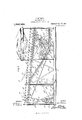
The invention is fully disclosed in the following specification of which the accompanying drawing forms a part, in which the separate parts of my invention are designated by suitable reference characters in each of the views, and in which Figures 1 and 1 are a side view of my improved mechanical toy device or apparatus;Fig. 2 a plan view thereof on a reduced scale with part of the construction broken away ;-Fig. 3 a sectional side View of a truck forming part of my improved toy ;Fig. 4C a partial section on the line l4i of Fig. 2; Fig. 5 a partial transverse section on the line 55 of Fig. 2; Fig. 6 a partial section on the line 6, of Fig. 2, and showing, diagrammatically, an electric circuit which I employ in connection with a motor forming part of the apparatus ;Fig. 7 a perspective view of details of the construction shown in Figs. 1 and 2 and on an enlarged scale, and ;Fig. 8 a bottom plan view of a truck which forms a part of my improvement.
In the practice of my invention, I provide a main oblong frame comprising a base a,
. side uprights a having lateral braces a and longitudinal braces a and for the purpose of this description, the end a of said frame will be called the front end and the end a the rear end, and the top of said frame is in- ,clined downwardly and rearwardly and is provided with parallel side bars a and parallel top rails a My invention also involves a truck 25, shown in. Fig. 1 and detached and in section in Fig. 3, and the frame is provided with a Specification of Letters Patent.
Application filed November 22, 1912.
Patented Apr. 15, 1913.
Serial No. 732,855.
tion 0 connected therewith at 6 and a backwardly and upwardly inclined portion 0 connected therewith at 0 and the forwardly and upwardly inclined portion 0 connects with an approximately horizontal portion 0 at c in the front top part of the frame,
while the upwardly and backwardly inclined portion 0 connects with an upwardly and backwardly inclined portion 0 con nected therewith at 0 and located in the rear end portion of the frame, and although I have described the separate parts of the main track as connected with each other, for the purpose of this description, it will be understood that said parts of said track are continuous, and the parts 0 0 c and 0 are all supported on corresponding frames consisting of parallel side members cl and cross bars (Z and the part c of the main track is supported on cross bars 6Z3 connected with the top side rails a of the main frame.
The supplemental track which is arranged over the main track is composed of parallel rails e and is downwardly and rearwardly inclined and consists of a central part 6 extending from c to 6 a front part a hinged at e and a rear part e hinged at e, and the rails of the central part c are supported on cross bars d secured to the frame rails a and the rails of the part c of the supplemental track are connected by a plate 7" and cross bars f and the front end of the plate 7" is cut out to form a recess f The rails of the main track, or the separate parts thereof, and the rails of the supplemental track, or the separate parts thereof, are all made of L-shaped metal strips or bars, as shown in Figs. 5 and 7, the latter figure representing one of the rails of the free end of the part c of the supplemental track and the corresponding rail 0 of the main track, and it will be understood that the construction at the free end of the part c of the supplemental track is the same, or approximately the same, as that shown in said figure, and it will also be seen that the base flanges e of the rails of the said parts of the supplemental track are provided with tongues e which rest on the base flanges of the rails 0 of the main track, while the upright or bearing port-ions of the rails of the said parts of the supplemental track are beveled, as shown at e, and rest on correspondingly beveled portions of the bearing parts of the rails c of the main track.
Mounted in the bottom front portion of the main frame is an electric motor 9 back of which is placed a battery 9 which is electrically connected with the said motor by means of wires 9 and g in the latter or which is placed a switch device 9 having an operating switch arm 9, and the motor 9 1s provided with a shaft 9 having a drive wheel 9 and mounted in the frame over said motor is a shaft it provided with a corresponding drive wheel h and mounted on the wheels and h is a belt if. The shaft h is provided with a small gear h which meshes with a larger gear 7L mounted on a shaft if supported in the main frame over the motor, and the shaft h is provided with a small gear h which meshes with a large gear it mounted on the shaft 2' supported in the main frame over the shaft 7L and provided with a sprocket wheel 2' Supported in the top portion of the main frame and rearwardly of the part c of the main track and between the rails of said track is a sprocket wheel 2", and supported centrally of the lower end portion of the part c of the main track is another sprocket wheel 1", and mounted on the sprocket wheels i i and i is a drive chain 2' and said chain is provided with a projecting tongue 2' which operates to draw the truck 6 up over the part c of the main track and onto the part 0 in the operation of the apparatus, as hereinafter described. The truck 5 com prises a hopper-shaped body portion 5 sup ported in and over a base plate 6 preferably of sheet metal and having downwardly directed side plates in which are mounted a front axle Z2 and rear axle b having flanged wheels 6 adapted to travel on both the main and the supplemental tracks. The base plate 6 of the truck is provided with an upright front end plate 6 and an upright rear end plate Z) with which is connected a back wardly directed V-shaped or triangular buffer 6 and in the front part of the truck be tween the hopper and the plate 6 is placed a weight 6 which is preferably secured to the hopper and to the base plate 6 The neck I) of the hopper extends downwardly through the base plate 6 and is provided with a trap door j hinged to the back side of the neck at 7' and this trap door is normally held closed by a yoke-shaped device 7' having side arms j which are passed outwardly through the side plates 6 of the truck and are provided with upwardly and backwardly directed extensions j and which, in the form of construction shown,
are provided with forwardly and downwardly directed loop members 7' having backwardly and downwardly directed arms provided with weights 7' I also provide a yoke-shaped device the side arms k of which rest on the front axle and are extended backwardly and provided with outwardly directed pivot members 73 which pass through the side plates 6* at k and this forms a pivotal support for the yoke-shaped device is, as will be readily understood, and the tongue i with which the drive chain i is provided operates in connection with this yoke-shaped device 7:. The front of the truck is also provided with a transverse rod 7."; which is passed transversely therethrough and the ends of which form stops 73, as shown in Fig. 8, and in the operation of opening the trap door of the hopper 6 as hereinafter described, the arms i are thrown forward, as indicated in dotted lines in Fig. 3 and rest on the stops 70.
Supported in the central part of the main frame and suspended between the central uprights a is a hopper m, a side view of which is given in Fig. 1 and a sectional View in Fig. 4, and the neck m of this hopper which is directed downwardly, is closed by a trap door m provided on the bottom thereof with a sectional longitudinal rib m which projects rearwardly and is provided with a slot 011; in which is pivoted at m a dog m which is shown in its normal position in Fig. 4, and the head of this dog is provided with a projecting angular nose m which operates in connection with a backwardly directed projection m on the rib m. The trap door m is also provided with side wings or plates m which fit in proximity to the sides of the hopper when said trap door is closed and form in connection with said trap door, a chute for directing the contents of the hopper m into the hopper b of the truck 6, when the trap door m is lowered in which operation the side wings or plates m enter the top of the hopper 79 as shown in Fig. 1.
At the back bottom portion of the hopper am I have secured bearing plates m and the pivot m of the trap door m passes through said bearing plates and a transverse rod m is also secured in said bearing plates, and passing transversely of and beneath the bottom of the trap door m and forwardly of the rib m is a yoke-shaped device n which is secured to said trap door and which is provided with backwardly and upwardly directed arms 12 having weights mi. The arms a of the yoke-shaped device n extends backwardly and upwardly adjacent to the sides of the hopper m and the operation of these arms is to hold the trap door m in a closed position, and said arms normally rest on the ends of the rod 111, which project for this purpose.
The main frame is provided directly over the hopper m and between the central uprights a with a hood 0 the bottom of which is open and provided with a transverse bearing 0 which is set below the bottom proper of said hood, and resting on said bearing, centrally of the bottom portion of the hood, is a downwardly curved plate spring 0 having a centrally directed end 0 secured to the front end of the hood, and the rear end of which extends backwardly and bears on a transverse hood member 0 Arranged longitudinally of the main track where the part 0 connects with the parts 0 is a rod 79 which is secured to one of the cross bars d at p and to another of said cross bars at 72 and the yoke-shaped device 7; rides on this rod 7) in the operation of the apparatus, as hereinafter described, and when the truck 6 moves into the position shown in Fig. 1 so as to enable said yoke-shaped device to clear the sprocket wheel 2' and also to enable the tongue 2' on the chain 2' to engage said yoke-shaped device. I also preferably secure in the front end portion of the part 0 of the main track an upwardly curved plate spring r the front end portion of which is secured at r and the rear end portion of which passes under one of the cross bars 6Z2 as shown at W, and the object of this spring is to retard the movementof the truck Z2 as it passes forwardly and backwardly over the part 0 of the main track.
The front end portion 6 of the supplemental track is normally held in the closed position, as shown in full lines in Fig. 1, by gravity, but the rear end portion 6 of said supplemental track is normally held in a raised or open position, as shown in full lines in Fig. 1 by a spring 8 which is secured to the hopper m as shown at s in Fig. 2, and which extends backwardly, centrally and longitudinally of the part 6 of the supplemental track and is curved downwardly below said part at s and extends upwardly and normally bears on cross bar .9 in said part c, and said spring passes under another cross bar .9 arranged centrally of said part of the supplemental track. The secured end of the spring 8 crosses the hinge e of the part c of the supplemental track and a hood t is preferably secured on the hopper m and extends backwardly over said hinge and. over the secured end of said spring.
The operation will be readily understood from the foregoing description when taken in connection with the accompanying drawing and the following statement thereof.
In the position of the truck Z) shown in full lines in Fig. 1, the contents of the hopper m have been dumped into the hopper b of the truck and the tongue 2' of the chain 71 engaging the yoke-shaped device 70, it being understood that the motor has been put in motion and the chain 2' is being driven in the direction of the arrows 00. As the op eration proceeds, the truck I) is moved up over the part 0 of the main track, as indi cated. at 00 and forwardly into the position shown at w in which position, the gear wheel 71. lifts the yoke-shaped device It out of engagement with the tongue 2'. The truck moves up under the part 6 of the supplemental track which is raised thereby, as shown in dotted lines in Fig. 1, but when the truck moves forwardly onto the part 0 of the main track, the part 6 of the supplemental track drops back into its normal position, as shown in full lines in Fig. 1. When the truck has been released from the chain 2' by the gear it as above described, said truck moves backwardly, by gravity, over the part c of the main track and over the parts 6 and e of the supplemental track and then over the part 6 of the supplemental track which is depressed, as shown in dotted lines in Fig. 1 and from which the truck moves onto the part 0 of the main track. The part c of the supplemental track is raised by the spring 8, as shown in full lines in Fig. 1, and the truck moves forwardly, by gravity, in which movement it passes downwardly over the part c of the main track and onto the part 0 of the main track, and into the position shown in full lines in Fig. 1, where the yoke-shaped device la is again engaged by the tongue i of the chain i and the above operation will be repeated as long as the motor is kept in operation. It must be presumed that the truck I) is normally loaded, the hopper Z2 thereof being filled with some small finely divided substance or substances, such as sand, gravel, shot or bullets, and as the truck moves back over the supplemental track, as hereinbefore described, into the position shown at m, and under the hood 0 the loop-shaped parts 7' of the arms 7' strike the cross bar 0 and are thrown into an upright position, as shown in dotted lines in Fig. 1, and the trap door 7' of the hopper b is opened, as indicated in dotted lines in Fig. 3, and the contents of said hopper drop out, or are dumped, into the hopper m, the bottom of which is normally closed, as shown in Fig. 1. In the movement of the truck 7) beneath the hood 0 as above described, the momentum of said truck is checked by the spring 0 until the contents thereof are discharged, as described, but the force of said spring is not suflicient to entirely stop the movement of the truck and after the above operation the said truck moves backwardly over the part 6 of the supplemental track and onto the part 0 of the main track, as shown at :0 When the truck moves onto the part 0 of the main track the part c of the supplemental track is raised, and the truck moves forwardly down over the part 0 of the main track and onto the part 0 As the truck moves forwardly over the part- 0 of the main track, the yoke-shaped device it; bears on the spring 1 which lessens the speed of the truck and said truck, in its normal movement, also strikes the dog of which raises into the position shown in dotted lines at m in Fig. 4. It will be understood that the truck will travel up on the part 0 of the main track to a slight extent under its momentum and will then move backwardly in which operation the rear axle of said truck will bear on the spring T which will arrest said backward movement to an extent, and the V- shaped projection If" at the back of the truck will again strike the dog in, which has again dropped into its normal position, and push it backwardly and this will open the trap door m in the bottom of the hopper m and the contents of said hopper will be again dumped into the hopper b of the truck. The truck having now been re-load ed, and being in the position shown at w in Fig. 1, the tongue 2' of the chain i will again engage the yoke-shaped device is and the truck will be moved upwardly over the part c of the main track and into the position shown at m and the described operation will be repeated as long as the motor 9 is in operation.
From the foregoing description it will be seen that the rear part 0 of the main track forms an extension of the supplemental track, as well as of the main track, which is also true of the front part 0 of the main track, as hereinbefore described, and taken as a whole, the main track consists of a central horizontal portion having upwardly inclined front and rear extensions and over which the supplemental track is placed, the front end extensions of the main track being provided with a supplemental extension slightly inclined toward the middle of the apparatus and the rear inclined portion of the main track being provided with a supplemental extension which is also inclined toward the center of the apparatus, said supplemental extension serving also as an extension for the supplemental track and the supplemental track being inclined to correspond with the inclination of the main track at the front of the apparatus. The end extension 0 of the main track in the rear end of the frame is provided with side guards u arranged outside of the rails c and which extend the full length of said part of the track and the object of which is to hold the truck on said part of the track, or prevent it jumping off of said part of the track when it passes off of the part 0 of the supplemental track thereonto.
My invention is not limited to the exact details of construction herein shown and described, nor to any particular power mechanism, and changes in and modifications of the construction described may be made, within the scope of the appended claims, without departing from the spirit of my invention or sacrificing its advantages.
Having fully described my invention what I claim as new and desire to secure by Letters Patent, is
1. In a mechanical toy device, a main oblong frame provided with a truck and main and supplemental tracks over which said truck is movable, the main track comprising a central horizontal portion having inclined end members and over which the supplemental track is placed, the inclined end members of the main track having end extensions both of which are inclined toward the center of the device and the supplemental track being also inclined to correspond with the inclination of one of said end extensions, and comprising a central part and end members hinged thereto and of which the end extensions of the main track also form extensions, one of said hinged members of the supplemental track being normally held in a raised position and being adapted to be depressed by the truck as it passes thereover.
2. In a mechanical toy device, a main oblong frame provided with a truck and main and supplemental tracks over which said ruck is movable, the main track comprising a central horizontal portion having inclined end members and over which the supplemental track is placed, the inclined end members of the main track having end extensions both of which are inclined toward the center of the device and the supplemental track being also inclined to correspond with the inclination of one of said end extensions, and comprising a central part and end members hinged thereto and of which the end extensions of the main track also form extensions, one of said hinged members of the supplemental track being normally held in a raised position and being adapted to be depressed by the trucl: as it passes thereover, and means for moving the truck up over one of the inclined end members of the main track onto one of the end extensions thereof.
3. In a mechanical toy device, a main oblong frame provided with a truck and main and supplemental tracks over which said truck is movable, the main track comprising a central horizontal portion having inclined end members and over which the supplemental track is placed, the inclined end members of the main track having end extensions both of which are inclined toward the center of the device and the supplemental track being also inclined to correspond with the inclination of one of said end extensions, and comprising a central part and end members hinged thereto and of which the end extensions of the main track also form extensions, one of said hinged members of the supplemental track being normally held in a raised position and being adapted to be depressed by the truck as it passes thereover, and means for moving the truck up over one of the inclined end members of the main track onto one of the end extensions thereof, the central part of the supplemental track being provided with a hopper which is suspended thereunder and provided with a trap door bottom and the truck being also provided with a hopper having a trap door bottom, and means whereby when the truck passes over the central part of the supple mental track, the contents thereof will be dumped into the hopper thereunder, and means whereby when the truck passes under said hopper 011 the main track, the contents of said hopper will be dumped into the truck.
4:- A mechanical toy device provided with a truck and main and supplemental tracks over which said truck is adapted to pass, the supplemental track being arranged over the main track and provided with a hopper which is suspended thereunder and provided with a trap door bottom, and the truck being also provided with a hopper having a trap door bottom, and means whereby when the truck moves over the supplemental track the contents thereof will be dumped into the hopper suspended thereunder, and other means whereby when the truck moves over the main track and under the hopper suspended from the supplemental track, the
contents thereof will be dumped into the truck.
In a mechanical toy, a frame provided with a truck and main and supplemental tracks over which the truck is movable, the supplemental track being placed over the main track, and the main track consisting of a central horizontal portion having upwardly inclined end extensions provided at their ends with supplemental extensions both of which are inclined toward the middle portion of the frame and one of which is higher than the other, the supplemental track consisting of a central part having end members which are hinged thereto and one of which is normally held in a raised position and adapted to be depressed by the truck when it moves thereover, the supplemental end extensions of the main track also serving as end extensions of the supplemental track and the supplemental track being inclined to correspond with the inclination of the higher supplemental end extension of the main track.-
6. In a mechanical toy, a frame provided with a truck and main and supplemental tracks over which the truck is movable, the supplemental track being placed over the main track, and the main track consisting of a central horizontal portion having upwardly inclined end extensions provided at their ends with supplemental extensions both of which are inclined toward the middle portion of the frame and one of which is higher than the other, the supplemental track consisting of a central part having end members which are hinged thereto and one of which is normally held .in a raised position and adapted to be depressed by the truck when it moves thereover, the supplemental end extensions of the main track also serving as end extensions of the supple mental track and the supplemental track being inclined to correspond with the inclination of the higher supplemental end extension of the main track, the central part of the supplemental track being also provided with a hopper which is suspended thereunder and provided with a trap door bottom and the truck being provided with a hopper having a trap door bottom, and means whereby when the truck moves over the supplemental track the contents thereof will be dumped into the hopper thereunder, and other means whereby when the truck moves over the central part of the main track the contents of said hopper will be dumped into said truck.
7. In a mechanical toy device of the class described, a frame provided with a truck and main and supplemental tracks over which said truck is movable, and the supplemental track being arranged over the main track, and being provided with hinged end members one of which is normally held in a raised position and adapted to be depressed by the truck as it passes thereover, and the main track being provided with upwardly inclined end members having supplemental end extensions which also form extensions for the hinged members of the supplemental track.
8. In a mechanical toy device of the class described, a frame provided with a truck and main and supplemental tracks over which said truck is movable, and the supplemental track being arranged over the main track and being provided with hinged end members one of which is normally held in a raised position and adapted to be depressed by the truck as it passes thereover, and the main track being provided with upwardly inclined endmembers having supplemental end extensions which also form extensions for the hinged members of the supplemental track, said supplemental track being provided centrally with a hopper which is suspended thereunder and is provided with a trap door bottom and the truck being also provided with a hopper having a trap door bottom, and means whereby when the truck passes over the supplemental track the contents thereof will be dumped into the hopper suspended thereunder, and means whereby when the truck passes over the supplemental parts of the main trackframe provided with a truck and main and supplemental tracks over which said truck is movable, the main track consisting of a central horizontal part having upwardly inclined end extensions in the front and back end portions of the frame, and supplemental end extensions in the front and back end portions of the frame, and the supplemental track consisting of a central part having hinged end members of which the supplemental end extensions of the main track also form extensions, the hinged end member of the supplemental track in the rear end por tion of the frame being normally held in a raised position and being depressed by the truck as it passes thereover, the supplemental track being also inclined downwardly and backwardly at an inclination which corresponds with the inclination of the supplemental end extension of the main track in the front end portion of the frame, an endless chain mounted in the front end portion of the frame and adapted to move the truck from the central portion of the main track up over the inclined part thereof and onto the end extension of said inclined part in the front end portion of the frame, and means for operating said chain.
10. In a mechanical toy device, a truck and main and supplemental tracks over which said truck is adapted to pass, the supplemental track being arranged over the main track and provided with a hopper which is suspended thereunder, and means whereby when the truck moves over the supplemental track the contents thereof will be dumped into said hopper, and other means whereby when the truck moves over the main track and under the hopper, the contents thereof will be dumped into said track.
In testimony that I claim the foregoing as my invention I. have signed my name in presence of the subscribing witnesses this 21st day of November 1912.
' JOHN MULLEN. \Vitnesses:
C. MULREANY, S. ANDREWS.
Copies of this patent may be obtained for five cents each, by addressing the Commissioner of Patents, Washington, D. G.
Priority Applications (1)
| Application Number | Priority Date | Filing Date | Title |
|---|---|---|---|
| US73285512A US1059064A (en) | 1912-11-22 | 1912-11-22 | Mechanical toy. |
Applications Claiming Priority (1)
| Application Number | Priority Date | Filing Date | Title |
|---|---|---|---|
| US73285512A US1059064A (en) | 1912-11-22 | 1912-11-22 | Mechanical toy. |
Publications (1)
| Publication Number | Publication Date |
|---|---|
| US1059064A true US1059064A (en) | 1913-04-15 |
Family
ID=3127317
Family Applications (1)
| Application Number | Title | Priority Date | Filing Date |
|---|---|---|---|
| US73285512A Expired - Lifetime US1059064A (en) | 1912-11-22 | 1912-11-22 | Mechanical toy. |
Country Status (1)
| Country | Link |
|---|---|
| US (1) | US1059064A (en) |
Cited By (1)
| Publication number | Priority date | Publication date | Assignee | Title |
|---|---|---|---|---|
| US4457660A (en) * | 1981-09-05 | 1984-07-03 | Elba-Werk Maschinen-Gesellschaft Mbh & Co. | Apparatus for storing and dispensing several bulk materials |
-
1912
- 1912-11-22 US US73285512A patent/US1059064A/en not_active Expired - Lifetime
Cited By (1)
| Publication number | Priority date | Publication date | Assignee | Title |
|---|---|---|---|---|
| US4457660A (en) * | 1981-09-05 | 1984-07-03 | Elba-Werk Maschinen-Gesellschaft Mbh & Co. | Apparatus for storing and dispensing several bulk materials |
Similar Documents
| Publication | Publication Date | Title |
|---|---|---|
| CA1079969A (en) | Transfer mechanism intended for use in toys | |
| US4068402A (en) | Toy vehicle and trackway | |
| US1713793A (en) | Amusement ride | |
| US4312149A (en) | Transfer mechanism utilizing a pivotable holding member | |
| US1890137A (en) | Amusement railway | |
| US2876584A (en) | Animated toy freight handling truck | |
| US834016A (en) | Amusement apparatus. | |
| US1290200A (en) | Conveying and loading mechanism. | |
| US1314238A (en) | Benjamin f | |
| US946200A (en) | Amusement apparatus. | |
| US1000219A (en) | Amusement apparatus. | |
| US1097615A (en) | Switchback-coaster. | |
| US1280032A (en) | Conveyer. | |
| US3456382A (en) | Toy with a track for a toy vehicle | |
| US615554A (en) | William hogan | |
| US2934853A (en) | Toy log loading station | |
| US1139955A (en) | Automatic toy. | |
| US559104A (en) | Street-railroad-car advertising device | |
| US1101250A (en) | Game apparatus. | |
| US1426027A (en) | Assigwos to wood equipment | |
| US555852A (en) | Half to michael iiolzman | |
| US1105271A (en) | Coaling device for trains in motion. | |
| US983584A (en) | Coal-elevator. | |
| US764201A (en) | Apparatus for removing dirt from excavations. | |
| US996286A (en) | Toy device. |