US1059059A - Locomotive ash-pan. - Google Patents
Locomotive ash-pan. Download PDFInfo
- Publication number
- US1059059A US1059059A US38397207A US1907383972A US1059059A US 1059059 A US1059059 A US 1059059A US 38397207 A US38397207 A US 38397207A US 1907383972 A US1907383972 A US 1907383972A US 1059059 A US1059059 A US 1059059A
- Authority
- US
- United States
- Prior art keywords
- pan
- ash
- upper portion
- air
- locomotive
- Prior art date
- Legal status (The legal status is an assumption and is not a legal conclusion. Google has not performed a legal analysis and makes no representation as to the accuracy of the status listed.)
- Expired - Lifetime
Links
- 230000003137 locomotive effect Effects 0.000 title description 8
- 238000010276 construction Methods 0.000 description 8
- 235000000396 iron Nutrition 0.000 description 7
- 239000003818 cinder Substances 0.000 description 4
- 239000002184 metal Substances 0.000 description 3
- 229910052751 metal Inorganic materials 0.000 description 3
- XEEYBQQBJWHFJM-UHFFFAOYSA-N Iron Chemical compound [Fe] XEEYBQQBJWHFJM-UHFFFAOYSA-N 0.000 description 2
- 229910000746 Structural steel Inorganic materials 0.000 description 2
- 238000007664 blowing Methods 0.000 description 2
- 239000002245 particle Substances 0.000 description 2
- 235000002918 Fraxinus excelsior Nutrition 0.000 description 1
- 229910000831 Steel Inorganic materials 0.000 description 1
- 239000002956 ash Substances 0.000 description 1
- 230000007547 defect Effects 0.000 description 1
- 238000009432 framing Methods 0.000 description 1
- 229910052742 iron Inorganic materials 0.000 description 1
- 238000000034 method Methods 0.000 description 1
- 238000012986 modification Methods 0.000 description 1
- 230000004048 modification Effects 0.000 description 1
- 229920000136 polysorbate Polymers 0.000 description 1
- 239000007787 solid Substances 0.000 description 1
- 239000010959 steel Substances 0.000 description 1
- 238000006467 substitution reaction Methods 0.000 description 1
- 238000010626 work up procedure Methods 0.000 description 1
Images

Classifications
-
- F—MECHANICAL ENGINEERING; LIGHTING; HEATING; WEAPONS; BLASTING
- F23—COMBUSTION APPARATUS; COMBUSTION PROCESSES
- F23J—REMOVAL OR TREATMENT OF COMBUSTION PRODUCTS OR COMBUSTION RESIDUES; FLUES
- F23J1/00—Removing ash, clinker, or slag from combustion chambers
-
- F—MECHANICAL ENGINEERING; LIGHTING; HEATING; WEAPONS; BLASTING
- F23—COMBUSTION APPARATUS; COMBUSTION PROCESSES
- F23B—METHODS OR APPARATUS FOR COMBUSTION USING ONLY SOLID FUEL
- F23B2700/00—Combustion apparatus for solid fuel
- F23B2700/006—Details of locomotive combustion apparatus
Definitions
- Figure 1 is a side; being cut) UNITED STATES PATENT OFFICE.
- This invention relates to ash-pans and, with regard to the more specific features thereof, to ash-pans of railway locomotives.
- One of the objects thereof is to provide an efiicient and practical ash-pan in which the chance of dropping hot coals is eliminated.
- Another object is to provide a durable and inexpensive ash-pan in which warpingv or burning out is done away with.
- Another object is to provide a construction of the above nature in which full and free draft is provided without chance of blowing live coals or cinders through the air inlet openings.
- Fig. 2 is an end view also partially in section.
- FIG. 1 of the accompanying drawings there is shown an ashpan the upper portion 1 of which is formed upon a framing formed of the angle irons 2, upon which the mud-ring of the boiler rests, and lower angle irons 3, the body of the pan being constituted of boiler steel and the parts riveted together as indicated in the drawings.
- the lower portion of the ash-pan comprises the sections 6 and 7, spaced, as indicated in the drawings, in the well-known manner in order to accommodate the driver axle.
- the forward portion comprises the upper angle iron 8, to which are secured depending angle irons 9 and 10 of the curved conformation indicated in Fig. 2 of the drawings.
- the section 7 is, in general, similar to section 6 having the upper angle irons l1 and the curved angle irons 12 and 13 depending therefrom, and the body of both of these sections is formed of boiler iron as in the case of the upper portion of the pan, being riveted to the angle iron frame-work and thus given a general semi-cylindrical form which possesses a high degree of mechanical strength and is substantially proof against warping in use.
- Sections 6 and 7 are provided with the ashdoors 14 and 15 having lining plates 23, each of which is hinged as at 16 and is normally secured in tightly closed condition as by the pin 17 and key 18'.
- the method of use of the above-described embodiment of this invention is substantially as follows: Upon cinders or hot coals falling into the ash-pan they drop into the lower portion thereof, which is sealed and forms thus a dead air space in which all fire is quickly extinguished. Any heat, moreover, which may be generated in this ortion of the pan can work no harmful e ect inasmuch as no appreciable warping of the curved sheets can occur and the doors are thoroughly protected by the liners as above set forth. No openings nor crevices obtain, moreover, through which heated particles can be dropped or blown, as is the case in former ash-pan constructions in which it has been unsuccessfully attempted to protect the openings by screens and the like.
- an ash-pan the combination of an upper portion open at its lower side; substantially semi-cylindrical lower portions making close joints with the upper portion; separable connections between said upper and lower portions; doors, a door being located in one end of each of said lower portions; and air ducts located in said upper portion and adapted to direct incoming air in a downward direction.
- An ash-pan comprising an upper section provided with air inlets and adapted to directthe incoming air in a downward direction; and a lower section adapted to receive and contain the hot ashes; and removable connections between said sections whereby the'lower section may be removed for repair or replacement without disturbing the upper section.
Landscapes
- Engineering & Computer Science (AREA)
- Mechanical Engineering (AREA)
- General Engineering & Computer Science (AREA)
- Processing Of Solid Wastes (AREA)
Description
. R. MOKEEN, JR. & J. H. GROVE.
LOGOMOTIVE ASH PAN.
APPLICATION FILED JULY 16 Patented Apr. 15, 1913.
2 SHEETS-SHEET 1.
/NVE/VTOBS WITNESSES W. R. MGKEEN, JR. & J. H. GROVE.
LOCOMOTIVE ASH PAN.
APPLICATION FILED JULY 16, 1907.
Patented Apr. 15,1913.-
2 SHEETS-SHEET 2.
Fi g 2 Lo 0 G...
WITNESSES OHNE S.
' ments of this invention,Figure 1 is a side; being cut) UNITED STATES PATENT OFFICE.
WILLIAM R. MOKEEN, JR., AND JAMES H. GROVE, OF OMAHA, NEBRASKA.
LOCOMOTIVE ASH-PAN.
Serial No. 383,972.
To all whom it may concern Be it known that we, WILnIAM R. Mo- KEEN, J r., and JAMES H. Guovn, residing at Omaha, in the county of Douglas and State of Nebraska, have invented certain new and useful Improvements in Locomotive Ash- Pans, of which the following is a full, clear, and exact description, such as will enable others skilled in the art to which it appertains to make and use the same.
This invention relates to ash-pans and, with regard to the more specific features thereof, to ash-pans of railway locomotives.
One of the objects thereof is to provide an efiicient and practical ash-pan in which the chance of dropping hot coals is eliminated.
Another object is to provide a durable and inexpensive ash-pan in which warpingv or burning out is done away with.
Another object is to provide a construction of the above nature in which full and free draft is provided without chance of blowing live coals or cinders through the air inlet openings.
Other objects will be in part obvious and in part'pointed out hereinafter.
This invention accordingly consists in the features of construction, combinations of elements and arrangement of parts which will be exemplified in the construction hereinafter set forth, and the scope of the application of which will be indicated in the following claims.
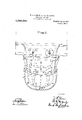
In the accompanying drawings, wherein is shown one of various possible embodielevation thereof, certain parts away in order to show the construction more clearly; and Fig. 2 is an end view also partially in section.
Similar reference characters refer to similar parts throughout both views of the drawings.
As tending to cast light upon certain features of this invention, it may here be noted that there is a tendency in ash-pans, and particularly those of the locomotive type, to warp or burn out by reason of the hot coals and cinders falling therein, which often work up a considerable fire in this part of the locomotive. This is particularly the case when air is admitted to the lower portion of the ash-pan on account of the strong draft due to high winds or the motionof the loco-- motive. Any warping or other deformation tends to permit the dropping of live coals,
with a tendency to set fire to wooden trestles or bridges, and such fires often occur with an ash-pan of the widely used types, even with the pan in good condition, by reason of the blowing of hot coals or cinders through the air-inlet openings. The above and other defects are eliminated in constructions of the nature of that hereinafter described.
Patented Apr. 15,1913.
Referring now to Fig. 1 of the accompanying drawings, there is shown an ashpan the upper portion 1 of which is formed upon a framing formed of the angle irons 2, upon which the mud-ring of the boiler rests, and lower angle irons 3, the body of the pan being constituted of boiler steel and the parts riveted together as indicated in the drawings. About the sides and end of this portion of the ash-pan are formed air inlet ports 4, the outer ends of which are guarded by upwardly flared shields 5, preferably likewise formed of sheet metal. The lower portion of the ash-pan comprises the sections 6 and 7, spaced, as indicated in the drawings, in the well-known manner in order to accommodate the driver axle. The forward portion comprises the upper angle iron 8, to which are secured depending angle irons 9 and 10 of the curved conformation indicated in Fig. 2 of the drawings. The section 7 is, in general, similar to section 6 having the upper angle irons l1 and the curved angle irons 12 and 13 depending therefrom, and the body of both of these sections is formed of boiler iron as in the case of the upper portion of the pan, being riveted to the angle iron frame-work and thus given a general semi-cylindrical form which possesses a high degree of mechanical strength and is substantially proof against warping in use. Sections 6 and 7 are provided with the ashdoors 14 and 15 having lining plates 23, each of which is hinged as at 16 and is normally secured in tightly closed condition as by the pin 17 and key 18'. These sections are thus, in normal use, substantially imperforate although means may be provided, if desired, as at 19, for an ash-pan blower should the same be used. Angle irons 8 and 11 are tightly held against the bottom angle irons 3 of the upper pins 20, provided with split keys 21, thus insuring a tight and secure joint and yet permitting the removal of the lower sections if desired. 4
The method of use of the above-described embodiment of this invention is substantially as follows: Upon cinders or hot coals falling into the ash-pan they drop into the lower portion thereof, which is sealed and forms thus a dead air space in which all fire is quickly extinguished. Any heat, moreover, which may be generated in this ortion of the pan can work no harmful e ect inasmuch as no appreciable warping of the curved sheets can occur and the doors are thoroughly protected by the liners as above set forth. No openings nor crevices obtain, moreover, through which heated particles can be dropped or blown, as is the case in former ash-pan constructions in which it has been unsuccessfully attempted to protect the openings by screens and the like. The draft is supplied to the grate through the air ports 4 and, by reason of the conformation of the shields 5, is forced inwardly in a'downward direction wardly to the fire-box. In this manner, even though a considerable degree of air pressure arises in the ash-pan, no particles can be blown through the airinlets as the incoming air rushes in a downward direction, tending to force all solid matter to the lower portion of the pan.
It will thus be seen that there is provided a construction in which the several objects essentially practical nature.
'so formed and disposed as above construction claim as new and of this invention are achieved, and that the same is cheap, strong and durable and of an The parts are apart and are not only eflioiently to perform their functions in the matter of retaining and extinguishing live coals and providing abundant draft to the grate, but as a whole to possess a high degree of mechanical strength and be capable of a long life in use.
As many changes could be made in the and many apparently widely different embodiments of this invention could be made without departing from the scope thereof, it is intended that all matter contained in the above description or shown in the accompanying drawings shall be interpreted as illustrative and not in a limiting,sense.
The essential features and combination of the invention will be particularly set quickly assembled or taken forth in the claims, and these are not to be limited to the particular structure illustrated, but are intended to include generically such modifications and substitutions of equivalents as reasonably fall within the scope of the invention.
Having described our invention, what we desire to secure by Letters Patent is v 1. In an ash-pan the combination of an and thence passes up upper portion formed of sheet metal and provided with angle bars at its upper and lower edges; a lower portion formed of sheet metal and provided with angle bars at its upper edges; and means adapted to secure the upper angle bars of said lower portion to the lower angle bars of said upper portion and form a substantially tight joint therebetween, said lower portion being in normal operative condition substantially imperforate and said upper portion being provided with air inlet ports and having secured thereon sheets adapted to guide the entering air in a downward direction.
2. In an ash-pan, the combination of an upper portion open at its lower side; a
depending lower portion closed at its bottom and sides and making a close joint with the upper portion; separable connections between said upper and lower portions; a door in one end of said lower portion; and inlet air ducts leadin the incoming air in a downward direction through the walls of said upper portion.
3. In anash-pan, the combination of an upper portion open at its lower side; depending lower portions closed at their bottoms and sides and making close joints with the upper portion; separable connections be tween the upper and said lower portions; doors, a door being located in one end of each of said lower portions; and inlet air ducts adapted to conduct incoming air in a downward direction through the walls of said upper portion.
In an ash-pan, the combination of an upper portion open at its lower side; substantially semi-cylindrical lower portions making close joints with the upper portion; separable connections between said upper and lower portions; doors, a door being located in one end of each of said lower portions; and air ducts located in said upper portion and adapted to direct incoming air in a downward direction.
5. An ash-pan comprising an upper section provided with air inlets and adapted to directthe incoming air in a downward direction; and a lower section adapted to receive and contain the hot ashes; and removable connections between said sections whereby the'lower section may be removed for repair or replacement without disturbing the upper section.
In testimony whereof we aflix our signatures, in the presence of two witnesses.
WILLIAM R. MoKEEN, JR. JAMES H. GROVE. Witnesses to both signatures:
JOHN A. Swo'r'rE, A. P. VAN ARSDALE.
Priority Applications (1)
| Application Number | Priority Date | Filing Date | Title |
|---|---|---|---|
| US38397207A US1059059A (en) | 1907-07-16 | 1907-07-16 | Locomotive ash-pan. |
Applications Claiming Priority (1)
| Application Number | Priority Date | Filing Date | Title |
|---|---|---|---|
| US38397207A US1059059A (en) | 1907-07-16 | 1907-07-16 | Locomotive ash-pan. |
Publications (1)
| Publication Number | Publication Date |
|---|---|
| US1059059A true US1059059A (en) | 1913-04-15 |
Family
ID=3127312
Family Applications (1)
| Application Number | Title | Priority Date | Filing Date |
|---|---|---|---|
| US38397207A Expired - Lifetime US1059059A (en) | 1907-07-16 | 1907-07-16 | Locomotive ash-pan. |
Country Status (1)
| Country | Link |
|---|---|
| US (1) | US1059059A (en) |
-
1907
- 1907-07-16 US US38397207A patent/US1059059A/en not_active Expired - Lifetime
Similar Documents
| Publication | Publication Date | Title |
|---|---|---|
| US310194A (en) | Michael a | |
| US759318A (en) | Hot-air furnace. | |
| US1177129A (en) | Spark-arrester. | |
| US230568A (en) | Spark-arrester | |
| US863597A (en) | Smoke-consuming boiler-furnace. | |
| US36639A (en) | Improvement in stoves | |
| US230955A (en) | Furnace for heating bolt-blanks | |
| US1119808A (en) | Grate. | |
| US150592A (en) | Improvement in furnaces and furnace-doors | |
| US1180369A (en) | Air-deflector for fire-box doors. | |
| US992123A (en) | Means for controlling the draft of locomotive-furnaces. | |
| US216888A (en) | Improvement in dumping dead-plates for furnaces | |
| US992122A (en) | Boiler-furnace. | |
| US770122A (en) | Steam-boiler furnace. | |
| US115515A (en) | Improvement in grates | |
| US6076A (en) | Mtjltiple-orrate ftmstace for | |
| US1102139A (en) | Grate. | |
| US517238A (en) | Smoke consumer | |
| US1097402A (en) | Steam-boiler. | |
| US404739A (en) | Exhaust mechanism | |
| US914314A (en) | Furnace. | |
| US261474A (en) | nepilly | |
| US718608A (en) | Smoke-consuming boiler-furnace. | |
| US874569A (en) | Furnace grate and ash-pit. | |
| US452414A (en) | Furnace |