US1059028A - Electric switch. - Google Patents
Electric switch. Download PDFInfo
- Publication number
- US1059028A US1059028A US58698410A US1910586984A US1059028A US 1059028 A US1059028 A US 1059028A US 58698410 A US58698410 A US 58698410A US 1910586984 A US1910586984 A US 1910586984A US 1059028 A US1059028 A US 1059028A
- Authority
- US
- United States
- Prior art keywords
- brush
- contact
- tip
- ups
- arm
- Prior art date
- Legal status (The legal status is an assumption and is not a legal conclusion. Google has not performed a legal analysis and makes no representation as to the accuracy of the status listed.)
- Expired - Lifetime
Links
- 238000010276 construction Methods 0.000 description 4
- 238000009413 insulation Methods 0.000 description 3
- 230000004048 modification Effects 0.000 description 2
- 238000012986 modification Methods 0.000 description 2
- 241001351439 Oneida Species 0.000 description 1
- 239000012634 fragment Substances 0.000 description 1
Images

Classifications
-
- G—PHYSICS
- G04—HOROLOGY
- G04C—ELECTROMECHANICAL CLOCKS OR WATCHES
- G04C23/00—Clocks with attached or built-in means operating any device at preselected times or after preselected time-intervals
Definitions
- My invention relates to an electric switch and I declare the following to be a full, clear, concise and exact description thereof, suflicient to enable any one skilled in the art I to make and use the same reference being had to the accompanying drawings in which like reference characters refer to like parts throughout the specification.
- the object of the invention is to provide a simple efficient switch whereby the lights of an electric display Sign may be automatically turned on and-o at any desired or given time of the day or night.
- the invention accomplishes this object by placing in circuit the mechanism of a clock adapted to revolve every twenty-four hours, a brush which is made to contact with the ends of any one or all successively of a plurality of members that represent a given period of time.
- the brush contacts with said members in a manner whereby the circuit is made, so long as it remains in contact and is broken immediately said brush passes, in its revolution, the end of said member or members.
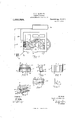
- FIG. 1 is a fragmentary, partial View of the mechanism of a clock in circuit with a switch and an electric display sign;
- F igs. 2, 3,4 and 5 are respectively, a front elevation, a side elevation, a rear and a perspective view of the switch;
- Fig. 6 is a plan View of a switch, showing certain modifications;
- Fig. 7 is a detail view of one of the members of said switch;
- Fig. 8 is a fragmentary view partially in section, showing the mounting of certain gear wheels;
- Fig. 9 is a plan view, in fragment, of a modified construct-ion;
- Fig. 10 is a sectional elevation of another modified construction;
- Fig. 11 is a plan of the construction shown in Fig. 10, completed; and
- Fig. 12 is a detail of a ring employed.
- any clock having a gear 1 mounted upon the hour spindle 2 thereof.
- Said gear 1 is in mesh with gear 3-adapted to make one revolution every twenty four hours.
- Gear 3 has suitably secured thereto an arm 4 carrying brush 5 adapted to contact with the ends 20 of any one or all successively of a plurality of tip ups 6, provided with bores or holes 7 in enlarged or sector portion 8 thereof, whereby same may be pivotally mounted upon rod 9 having bearings at either end in the sides 10 and 11 of easing 7.
- the rota-- -tion rearward of tip ups 6 is limited by interference rod 12- also having bearings in sides 10 and 11 of easing 7.
- the invention embodies yoke 14 pivotally mounted as at 15 and 16 in sides 10 and 11 of easing 7.
- Said yoke 14 is held normally in the position shown in Fig. 5 or with bar 24 thereof upon the up per surfaces of ends 20 of tip ups 6, by coiled spring 21 mounted upon rod 22 and having its ends hooked over arm or handle 23 of yoke 14 and edge of side 10 of casing 7.
- Said rod 22 has bearings in sides 10 and 11 of easing 7 and forms pivotal supports for yoke 14.
- Yoke 14 is provided with handle 23 whereby the operator may rotate yoke 14 so as to raise bar 24 thereof and permit the rotation of any one or all of tip ups 6 whereby ends 20 thereof may come to rest on top of bar 24 of yoke 14, so that any one or all of ends 20 of tip ups 6 may be held above the plane in which brush 5 of arm 4 moves and thus permit the withdrawal from the circuit of that particular half hour represented by that particular end 20 of tip up 6.
- each end 20 of tip ups 6 represent a half hour of time and hence in order to provide or adapt brush 5 of arm 4 to remain in contact an equal space or period of time with each end 20, the tip ups 6 having ends 20 with the greatest amount of'curvature are proportionally lessened in thickness.
- Fig. 6 I have shown a modified form of electric switch embodying a plurality of contact plugs 30 having handles 31 and held in casing 32 adapted to permit the rearward sliding of said plugs 30, so that any one or all thereof may be removed from the line of contact with brush 5 of arm 4.
- Plugs 30 have lugs 5 adapted to engage cross arms (ZZ to limit the movement forward and rearward of said plugs 30.
- I" mount same in an insulating manner by insulation upon frame 40 of any suitable clock mechanism. Said switch is so disposed that brush 5 of arm 4 will just contact with ends 20 of tip ups 6, in its revolutionary movement, when said ends 20 are disposed in the plane of said brush 5.
- One wire 41 leading from battery 42, or any suitable electric generator, may be connected directly to the frame 43 of the clock mechanism, and the other wire 44 connected to the electric sign 46. ire 41 is connected with the sign 46 and with switch, which I shall term generally 45, to complete the cir-' cuit.
- tip ups representing said hours eight and nine oclock are left in their normal position, whereby contact with brush 5 of arm 4 may be made, and the remaining tip ups 6 are disposed with their ends 20 above bar 24 of yoke 14, so that same will not contact with brush 5 of arm 4, when said brush passes in its revolution said ends.
- gear wheel 3 may be insulated from the rest of the frame of the clock by insulation as at 50. It will also be necessary in this instance to insulate gear 1 as at 51. Further, there is mounted upon gear wheel 3 a me tallic disk 52 in a manner so that said disk 52 will be held above said wheel 3 by collar 53 secured to wheel 3 and to disk 52 in any suitable manner.
- An arm 54 insulated by 60 from the frame 43 of the clock to which it is indirectly secured has an elbow 56 adapted to contact with the upper surface of disk 52 and is connected with wire 41 from the battery 42.
- Tip ups 70 are mounted in a pivotal manner by rod 71 upon base 72 mounted upon frame 43 of the clock by insulation blocks 73.
- a wire hoop 74 is employed to hold any one or all of tip ups 70 in angular posit-ion, as seen by dotted lines in Fig. 10, whereby brush 75 secured to elbow 76 of arm 77 mounted upon a gear wheel 78 similar to wheel 3 of the former construction, may not make contact with the ends 79 of tip ups 70.
- any clock mechanism may be employed in combination with the electric switch described, and any disposition of said switch on said clock frame may be made by well known gear mounting.
- the clock mechanism here shown is an eight day pendulum movement.
- the device may also be employed in any instance where any given make and break period in an electric circuit is desirable.
- an arm having a brush having a brush
- clock mechanism for moving said arm circumferentially
- a casing pivotally holding a plurality of tip ups
- a yoke pivotally mounted to said casing
- spring means for holding said yoke normally upon the upper surfaces of the ends of said tip ups, whereby said ends may lie in a plane to contact with said brush
- said ends of said tip ups adapted to be swung upon the upper side of said yoke, whereby to avoid contact with said brush, substantially as described.
Landscapes
- Physics & Mathematics (AREA)
- General Physics & Mathematics (AREA)
- Motor Or Generator Current Collectors (AREA)
Description
P. H; CADOGAN.
ELECTRIC SWITCH.
APPLICATION FILED 001". 14, 1910.
1,059,028, Patented Apr. 15, 1913.
2 BHEETS-SHEET 1.
WlTNESSES: .INVENTOR FRANK H. GAJJOGAN TORNEYS BIA PLANOURAPH C04. WASHINGTON. [L c,
F. H. GADOGAN.
ELEOTBIO SWITCH.
APPLICATION FILED 00114, 1910.
1,059,028. Patented Apr. 15, 1913.
. 2 SHEETS-SHEET 2.
' INVENTOR F AN H. CAJJOGA/V f *l ava ATTORNEYS FRANK H. CADOGAN, OF UTICA, NEW YORK.
ELECTRIC SWITCH.
Specification of Letters Patent.
Patented Apr. 15, 1913.
Application filed October 14, 1910. Seria1No. 586,984.
To all whom it may concern:
Be it known that I, FRANK H. CADOGAN, citizen of the United States, residing at Utica, in the county of Oneida and State of New York, have invented certain new and useful Improvements in Electric Switches, of which the following is a specification, ref erence being had therein to the accompanying drawing.
My invention relates to an electric switch and I declare the following to be a full, clear, concise and exact description thereof, suflicient to enable any one skilled in the art I to make and use the same reference being had to the accompanying drawings in which like reference characters refer to like parts throughout the specification.
The object of the invention is to provide a simple efficient switch whereby the lights of an electric display Sign may be automatically turned on and-o at any desired or given time of the day or night. The invention accomplishes this object by placing in circuit the mechanism of a clock adapted to revolve every twenty-four hours, a brush which is made to contact with the ends of any one or all successively of a plurality of members that represent a given period of time. The brush contacts with said members in a manner whereby the circuit is made, so long as it remains in contact and is broken immediately said brush passes, in its revolution, the end of said member or members. This and other objects will be readily apparent from the drawings, in which- Figure 1 is a fragmentary, partial View of the mechanism of a clock in circuit with a switch and an electric display sign; F igs. 2, 3,4 and 5 are respectively, a front elevation, a side elevation, a rear and a perspective view of the switch; Fig. 6 is a plan View of a switch, showing certain modifications; Fig. 7 is a detail view of one of the members of said switch; Fig. 8 is a fragmentary view partially in section, showing the mounting of certain gear wheels; Fig. 9 is a plan view, in fragment, of a modified construct-ion; Fig. 10 is a sectional elevation of another modified construction; Fig. 11 is a plan of the construction shown in Fig. 10, completed; and Fig. 12 is a detail of a ring employed.
Referring to the drawings more particularly, I have here shown the partial'mechanism of any clock having a gear 1 mounted upon the hour spindle 2 thereof. Said gear 1 is in mesh with gear 3-adapted to make one revolution every twenty four hours. Gear 3 has suitably secured thereto an arm 4 carrying brush 5 adapted to contact with the ends 20 of any one or all successively of a plurality of tip ups 6, provided with bores or holes 7 in enlarged or sector portion 8 thereof, whereby same may be pivotally mounted upon rod 9 having bearings at either end in the sides 10 and 11 of easing 7. The rota-- -tion rearward of tip ups 6 is limited by interference rod 12- also having bearings in sides 10 and 11 of easing 7.
In order to hold any one or all of tip ups 6 in angular position with reference to base 13 of casing 7 or so that ends 20 will be raised above a plane in which brush 5 of arm 4 moves, the invention embodies yoke 14 pivotally mounted as at 15 and 16 in sides 10 and 11 of easing 7. Said yoke 14 is held normally in the position shown in Fig. 5 or with bar 24 thereof upon the up per surfaces of ends 20 of tip ups 6, by coiled spring 21 mounted upon rod 22 and having its ends hooked over arm or handle 23 of yoke 14 and edge of side 10 of casing 7. Said rod 22 has bearings in sides 10 and 11 of easing 7 and forms pivotal supports for yoke 14. Yoke 14 is provided with handle 23 whereby the operator may rotate yoke 14 so as to raise bar 24 thereof and permit the rotation of any one or all of tip ups 6 whereby ends 20 thereof may come to rest on top of bar 24 of yoke 14, so that any one or all of ends 20 of tip ups 6 may be held above the plane in which brush 5 of arm 4 moves and thus permit the withdrawal from the circuit of that particular half hour represented by that particular end 20 of tip up 6.
The ends 20 of tip ups 6 are beveled in order that when the plurality of said ends are assembled the whole will'be disposed in the arc of a circle. In the drawings shown, each end 20 of tip ups 6 represent a half hour of time and hence in order to provide or adapt brush 5 of arm 4 to remain in contact an equal space or period of time with each end 20, the tip ups 6 having ends 20 with the greatest amount of'curvature are proportionally lessened in thickness.
In Fig. 6 I have shown a modified form of electric switch embodying a plurality of contact plugs 30 having handles 31 and held in casing 32 adapted to permit the rearward sliding of said plugs 30, so that any one or all thereof may be removed from the line of contact with brush 5 of arm 4. Plugs 30 have lugs 5 adapted to engage cross arms (ZZ to limit the movement forward and rearward of said plugs 30.
To properly connect the switch for actual operation, I" mount same in an insulating manner by insulation upon frame 40 of any suitable clock mechanism. Said switch is so disposed that brush 5 of arm 4 will just contact with ends 20 of tip ups 6, in its revolutionary movement, when said ends 20 are disposed in the plane of said brush 5. One wire 41 leading from battery 42, or any suitable electric generator, may be connected directly to the frame 43 of the clock mechanism, and the other wire 44 connected to the electric sign 46. ire 41 is connected with the sign 46 and with switch, which I shall term generally 45, to complete the cir-' cuit. If it is desired to-have the sign 46 lighted during any period of time, say during the hours eight and nine oclock of the evening, tip ups representing said hours eight and nine oclock are left in their normal position, whereby contact with brush 5 of arm 4 may be made, and the remaining tip ups 6 are disposed with their ends 20 above bar 24 of yoke 14, so that same will not contact with brush 5 of arm 4, when said brush passes in its revolution said ends.
Atthe hour of eight oclock, brush 5 of arm 4 will move into contact with ends 20 of tip ups 6 representing said hour and will remain in contact during the hour of eight oclock whereupon it will move to the ends 20 of tip ups 6 representing nine oclock, which ends will be adjacent those represent-- ing eight oclock, and will remain in contact here during said hour of nine oclock. After the hour of nine oclock is passed or at ten oclock, brush 5 of arm 4 will move out of contact with the ends 20 of tip ups representing eight and nine oclock and the electric circuit will be broken, whereupon the display sign 46 will have its lights turned off for the remainder of the night or until the brush 5 again comes in contact with said ends after the lapse of twentyfour hours.
In the event that it may be found desirable to connect wire 41 so that the current will not pass through frame 43 of the clock, gear wheel 3 may be insulated from the rest of the frame of the clock by insulation as at 50. It will also be necessary in this instance to insulate gear 1 as at 51. Further, there is mounted upon gear wheel 3 a me tallic disk 52 in a manner so that said disk 52 will be held above said wheel 3 by collar 53 secured to wheel 3 and to disk 52 in any suitable manner. An arm 54 insulated by 60 from the frame 43 of the clock to which it is indirectly secured has an elbow 56 adapted to contact with the upper surface of disk 52 and is connected with wire 41 from the battery 42.
In Figs. 10 and 11 I have shown a still further modification embodying the idea of having the switch turn on or off the electric current at any period of the twenty-four hours of the day. Tip ups 70 are mounted in a pivotal manner by rod 71 upon base 72 mounted upon frame 43 of the clock by insulation blocks 73. A wire hoop 74 is employed to hold any one or all of tip ups 70 in angular posit-ion, as seen by dotted lines in Fig. 10, whereby brush 75 secured to elbow 76 of arm 77 mounted upon a gear wheel 78 similar to wheel 3 of the former construction, may not make contact with the ends 79 of tip ups 70.
Obviously any clock mechanism may be employed in combination with the electric switch described, and any disposition of said switch on said clock frame may be made by well known gear mounting. The clock mechanism here shown is an eight day pendulum movement. The device may also be employed in any instance where any given make and break period in an electric circuit is desirable.
Having thus described my invention what I claim as new and desire to secure by Letters Patent is:
1. In a device of the character described, the combination of an arm having a brush, clock mechanism for moving said arm circumferentially, a casing pivotally holding a plurality of tip ups, a yoke pivotally mounted to said casing, spring means for holding said yoke normally upon the upper surfaces of the ends of said tip ups, whereby said ends may lie in a plane to contact with said brush, and said ends of said tip ups adapted to be swung upon the upper side of said yoke, whereby to avoid contact with said brush, substantially as described.
2. In a device of the character described, the combination with an electric sign, a source of electric energy, a clock-mechanism and a series of tip-ups with ends adapted to complete a circuit including the sign, the said electric-energy source and the clock, the said tip-ups being parallel with each other their ends forming a part of a circle and of a width whereby their contactends all present an equal surface for the travel of the contacting mechanism.
In testimony whereof I have hereunto affiXed my signature in the presence of two witnesses;
FRANK H. OADOGAN. I
IVitnesses ELEANOR T. DE Groncr, T. L. IVILDER.
Copies of this patent may be obtained for five cents each, by addressing the Commissioner of Patents.
Washington, I). G.
Priority Applications (1)
| Application Number | Priority Date | Filing Date | Title |
|---|---|---|---|
| US58698410A US1059028A (en) | 1910-10-14 | 1910-10-14 | Electric switch. |
Applications Claiming Priority (1)
| Application Number | Priority Date | Filing Date | Title |
|---|---|---|---|
| US58698410A US1059028A (en) | 1910-10-14 | 1910-10-14 | Electric switch. |
Publications (1)
| Publication Number | Publication Date |
|---|---|
| US1059028A true US1059028A (en) | 1913-04-15 |
Family
ID=3127281
Family Applications (1)
| Application Number | Title | Priority Date | Filing Date |
|---|---|---|---|
| US58698410A Expired - Lifetime US1059028A (en) | 1910-10-14 | 1910-10-14 | Electric switch. |
Country Status (1)
| Country | Link |
|---|---|
| US (1) | US1059028A (en) |
-
1910
- 1910-10-14 US US58698410A patent/US1059028A/en not_active Expired - Lifetime
Similar Documents
| Publication | Publication Date | Title |
|---|---|---|
| US548744A (en) | Electric switch | |
| US2300513A (en) | Time switch mechanism | |
| US1058545A (en) | Annunciator system. | |
| US2806910A (en) | Clocks | |
| US666381A (en) | Illuminated clock. | |
| US1383564A (en) | Heating apparatus | |
| US1065513A (en) | Automatic electric display-sign. | |
| US569764A (en) | Charles l | |
| US2114759A (en) | Direction signal for motor oars | |
| US1192949A (en) | Suction-sweeper. | |
| US356605A (en) | jones | |
| US952710A (en) | Alarm apparatus. | |
| US1463253A (en) | Time switch | |
| US618646A (en) | Electric illuminated clock-dial | |
| US976214A (en) | Signal attachment for clocks. | |
| US407945A (en) | Electric clock for use in exposed places | |
| US1441069A (en) | Electric illuminated clock dial | |
| US1508876A (en) | Combined illuminating and time-indicating means | |
| US1547803A (en) | Time switch | |
| US246211A (en) | David rousseau | |
| US1385656A (en) | bates | |
| US944802A (en) | Time-switch. | |
| US751781A (en) | So model | |
| US1763902A (en) | Flash light | |
| US2061312A (en) | Electric time switch |